


1 |
FEATURES |
|
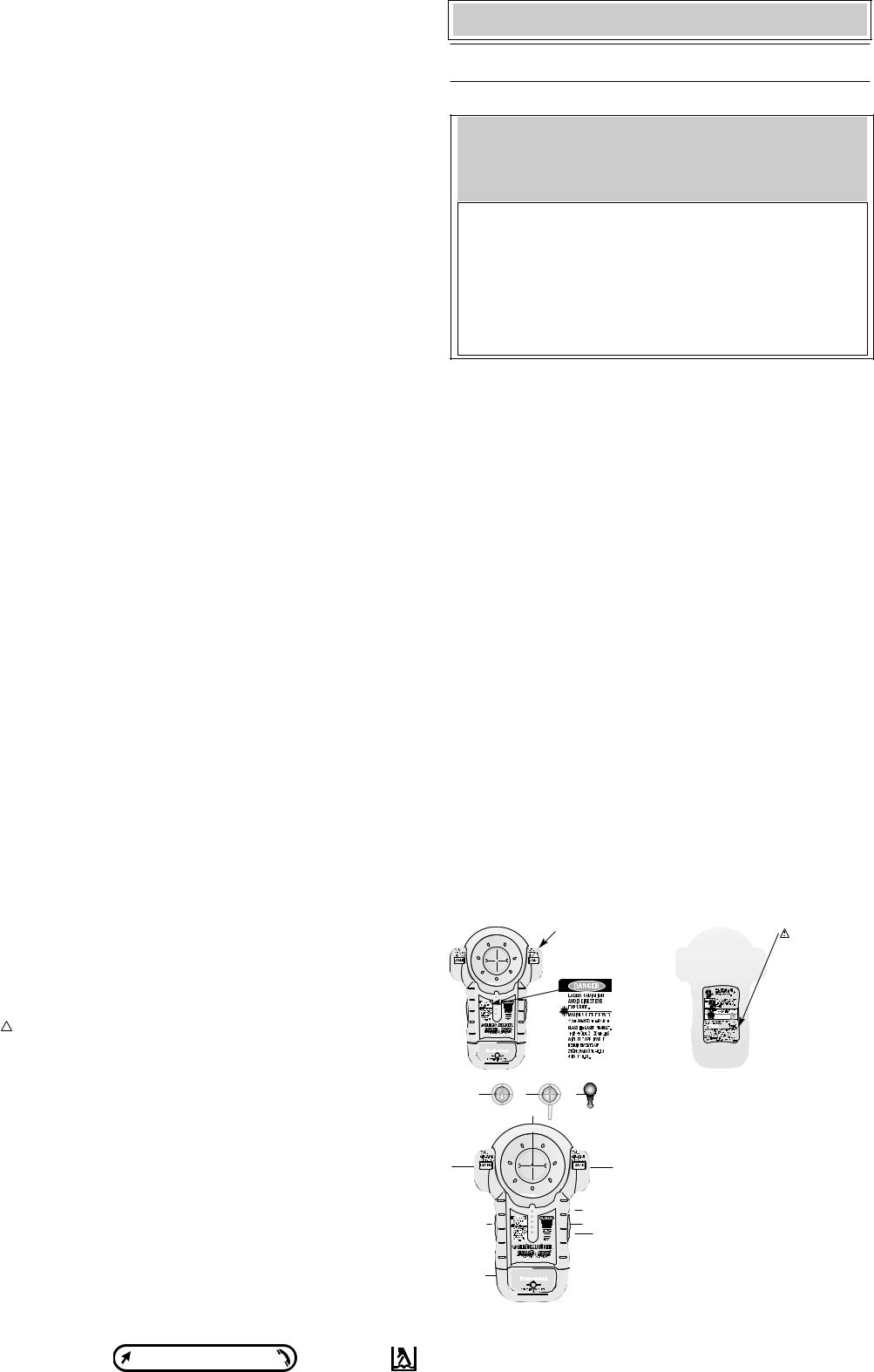
1.) Marking/Hanging Insert |
1 |
1a.) Hanging Insert (keyhole) |
BullseyeTM Laser Level and Stud Finder |
1b.) Spacer Insert |
|
|
INSTRUCTION MANUAL |
1c.) Drywall Pin |
2.) Laser On/Off Button |
|
6 |
3.) Stud Finder On/Off |
|
Button |
|
4.) Red LED’s (Light Emitting |
Catalog No. BDL100S |
Diodes) |
|
BEFORE RETURNING THIS PRODUCT
FOR ANY REASON PLEASE CALL
1-800-54-HOW-TO (544-6986)
IF YOU SHOULD EXPERIENCE A PROBLEM
WITH YOUR BLACK & DECKER PRODUCT,
CALL 1-800-54-HOW-TO (544-6986)
2
BEFORE YOU CALL, HAVE THE FOLLOWING INFORMATION AVAILABLE, CATALOG No., TYPE No., AND DATE CODE (e.g. 20000130M). IN MOST CASES, A BLACK & DECKER REPRESENTATIVE CAN RESOLVE YOUR PROBLEM OVER THE PHONE. IF YOU HAVE A SUGGESTION OR COMMENT, GIVE US A CALL. YOUR FEEDBACK IS VITAL TO BLACK & DECKER.
2

5
4A.) Green LED
5.) Battery Compartment
Cover
6.) Self-Leveling Laser
Lines
SAVE THIS MANUAL FOR FUTURE REFERENCE.
VEA EL ESPAÑOL EN LA CONTRAPORTADA.
INSTRUCTIVO DE OPERACIÓN, CENTROS DE SERVICIO Y PÓLIZA DE GARANTÍA.
ADVERTENCIA: LÉASE ESTE INSTRUCTIVO ANTES DE USAR EL PRODUCTO.
Cat No. BDL100S Form # 611195-00 (JUN-02-1) Copyright © 2002 Black & Decker Printed in China
 WARNING: Read and understand all instructions. Failure to follow all instructions listed
below may result in electric shock, fire and/or serious personal injury.
5
SAVE THESE INSTRUCTIONS
Safety Instructions
•Do not operate the laser in explosive atmospheres, such as in the presence of flammable liquids, gases, or dust.
•Use the laser only with the specifically designated batteries. Use of any other batteries may create a risk of fire.
•Store idle laser out of reach of children and other untrained persons. Lasers are dangerous in the hands of untrained users.
•Use only accessories that are recommended by the manufacturer for your model.
Accessories that may be suitable for one laser, may create a risk of injury when used on another laser.
• Do not use optical tools such as a telescope or transit to view the laser beam. Serious eye injury could result.
• Do not place the laser in a position which may cause anyone to intentionally or unintentionally stare into the laser beam. Serious eye injury could result
• Turn the laser off when it is not in use. Leaving the laser on increases the risk of staring into the laser beam.
• Repairs and servicing MUST be performed by a qualified repair facility. Repairs performed by unqualified personnel could result in serious injury.
• WARNING: DO NOT DISASSEMBLE THE LASER. There are no user serviceable parts inside. Disassembling the Laser will void all warranties on the product. Do not modify the product in any way Modifying the tool may result in Hazardous Laser Radiation Exposure.
•Do not operate the laser around children or allow children to operate the laser. Serious eye injury may result.
• |
Do not remove or deface warning labels. Removing labels increases the risk of exposure to |
7 |
|||
|
radiation. |
|
|
|
|
• |
Position the laser securely. Damage to the laser or serious injury could result if the laser |
|
|||
|
falls. |
|
|
|
|
• |
CAUTION: Use caution when drilling, nailing or cutting into walls, floors and ceilings |
|
|||
|
which may contain electrical wiring or pipes. These items may be detected by the Bullseye |
|
|||
|
Stud Finder in the same manner in which studs are detected. Because studs are normally |
|
|||
|
spaced 16 inches or 24 inches apart and are 1-1/2 inches wide, beware of anything closer |
|
|||
|
together or of a different width. Always turn off the power when working near electrical |
|
|||
|
wires. |
|
|
|
|
|
CAUTION: Use of controls or adjustments or performance of procedures other than |
|
|||
|
those specified in this manual may result in hazardous laser radiation exposure. |
|
|||
|
The label on your tool may include the following symbols. |
|
|
||
|
V .......................... |
volts |
mW...................... |
milliwatts |
|
|
nm ........................ |
wavelength in nanometers |
IIIa ...................... |
Class IIIa Laser |
|
|
For your convenience and safety, the following labels are on your laser. |
|
|
||
Avoid expo- sure-Laser radiation emitted from this aperture.
 WARNING: To reduce the risk of injury, user must read and understand instruction manual.
9
Before |
|
Avant |
Wall |
Antes |
|
|
Mur |
|
Pared |
After |
|
Après |
Spacer |
Después |
Pièce d’espacement |
|
Pieza espaciadora |
Installing the Battery
Ensure laser on/off switch is in the full off position. Remove the battery compartment cover (5) by pressing down in the center of the cover as shown in Fig. 2 and pulling back. Insert a fresh 9 volt battery making sure to match (+) and (-) terminals correctly. Replace the battery compartment cover.
Operating Instructions
STUD FINDER
Stud Scan Mode: (Finds metal or wood studs through up to 3/4” drywall.) Place unit flat against wall as shown in Figure 3. Press in on the stud finder ON/OFF button (3) and hold for normal Stud Scan mode. The bottom red LED (4) will light and the unit will beep once while it is calibrating. Slide unit slowly, Figure 4, horizontally across surface of wall without lifting or tilting. When the first red LED lights, slow down and keep sliding until the top green LED is lit and beep sounds as shown in Figure 5. This is the stud edge. Mark this spot (through the central hole of the marking insert). Keep moving past mark until lights go out. Continue holding button and reverse direction. Mark other stud edge. Center of stud is between two marks.
LASER
Place unit flat against wall as shown in Figure 3. Push up on the laser on/off button (2) to activate the self-leveling laser lines. To hang the unit on the wall, push pin (1c) through marking insert into drywall as shown in Figure 6. When pressing pin into drywall, make sure it is straight and seated firmly in the marking insert and that the unit is secure on the wall.
 CAUTION: Pin is sharp and should be handled with care. NOTE: The drywall pin can only be used with the marking insert (1), and is only for drywall, NOT other surfaces including plaster. For surfaces other than drywall, the (key hole) hanging insert (1a) can be used with a standard screw or nail in a predrilled hole. Make sure it is straight and seated firmly in the insert and that the unit is secure on the wall. The drywall pin should always be pushed in by hand and never driven by a hammer. To remove the insert, push it out from the front side of the unit.
Figure 7 illustrates a typical application for the Bullseye Laser Level when it is wall mounted. When visibility is poor or when using laser outdoors, use the marking cone to enhance the laser line as shown in Figure 8. To extend the line, use the spacer insert (1b) which is shown in Figure 9. NOTE: Because the spacer insert keeps the unit farther from the wall, the stud sensor can not be used when using the spacer insert.
 DANGER: Laser Radiation, avoid direct eye exposure.
Helpful Hints
•If the laser light becomes dim or is no longer visible when the switch is in the on position check or change the battery.
•The laser lines are only level on the wall against which the unit is held or hung. The short line visible on any adjacent wall is not level.
•The laser unit is a wall use tool only and only generates level lines when held against a vertical surface.
•The laser unit is equipped with a self leveling pendulum lock that stops pendulum motion when the laser on/off switch is moved to the off position.
•If the laser on/off switch is pushed part way to the on position, the laser lines may be on while the pendulum lock is still engaged.
TROUBLESHOOTING
|
|
Problem |
Possible Cause |
Solution |
|||||
|
|
• LEDs do not light. |
• Weak battery. |
|
|
• Replace with fresh battery. |
|||
|
|
|
|
• Nothing to detect in that |
• Start again moving farther to either |
||||
|
|
|
|
area. |
|
|
|
side. |
|
|
|
|
|
• The laser on/off switch |
• Be sure laser on/off switch is in the |
||||
|
|
|
|
must be pushed to the |
full on position. |
||||
|
|
|
|
full on position. |
|
|
|
|
|
|
|
|
|
• Check mode. May have |
|
|
|||
|
|
|
|
been calibrated over a |
|
|
|||
|
|
|
|
stud. |
|
|
|
|
|
|
|
|
|
|
|
|
|
||
|
|
• LED lights and sound |
|
|
|||||
|
|
• Wall thickness is over |
• Thickness must be less than 3/4 |
||||||
|
|
stay on. |
|
3/4 inch thick. |
|
|
inch to calibrate and work properly. |
|
|
|
|
|
|
|
|
|
|
|
|
|
|
|
|
|
|
|
|
|
|
|
|
|
|
|
|
|
|
|
|
|
|
• LEDs light in too many |
• Detects other objects |
• Because studs are normally |
|||||
|
|
places. |
besides studs. |
|
|
spaced 16 inches or 24 inches |
|||
|
|
|
|
• Electrical wiring and |
apart and are 1-1/2 inches wide, |
||||
|
|
|
|
metal or plastic pipes |
beware of anything closer together |
||||
|
|
|
|
may be near or touching |
or of a different width. |
||||
|
|
|
|
back surface of wall. |
|
|
|
|
|
|
|
• Laser does not project on |
• The self leveling range |
• Be sure that the unit is as straight |
|||||
|
|
wall. |
of the unit is +/-5 degrees, |
up and down as possible. |
|||||
|
|
|
|
if the unit is not held |
|
|
|||
|
|
|
|
within 5 |
degrees |
of |
|
|
|
|
|
|
|
vertical, the laser lines |
|
|
|||
|
|
|
|
will not project on wall. |
|
|
|||
|
|
• Laser projects on wall |
• Wall on which the unit is |
• Use the unit against vertical walls |
|||||
|
|
but lines are not level. |
mounted or held must be |
only, lines will not be level on sloped |
|||||
|
|
|
|
within +/- 5 degrees of |
walls or other non-vertical surfaces. |
||||
|
|
|
|
vertical |
for the |
self |
|
|
|
leveling mechanism to function correctly. If this is exceeded, the lines will still project but may not be level.
Storage
Always store the Bullseye Laser Level and Stud Finder indoors and in its protective case.
Maintenance
Use only mild soap and damp cloth to clean the tool. Never let any liquid get inside the tool; never immerse any part of the tool into a liquid.
IMPORTANT: To assure product SAFETY and RELIABILITY, repairs, maintenance and adjustment (other than those listed in this manual) should be performed by authorized service centers or other qualified service organizations, always using identical replacement parts.
Accessories
Recommended accessories for use with your tool are available from your local dealer or authorized service center. If you need assistance regarding accessories, please call:
1-800-54-HOW-TO (544-6986).
 WARNING: The use of any accessory not recommended for use with this tool could be hazardous.
Service Information
All Black & Decker Service Centers are staffed with trained personnel to provide customers with efficient and reliable power tool service. Whether you need technical advice, repair, or genuine factory replacement parts, contact the Black & Decker location nearest you. To find your local service location, refer to the yellow page directory under "Tools—Electric" or call:
1-800-54-HOW TO. (544-6986)
Full Two-Year Home Use Warranty
Black & Decker (U.S.) Inc. warrants this product for two years against any defects in material or workmanship. The defective product will be replaced or repaired at no charge in either of two ways.
The first, which will result in exchanges only, is to return the product to the retailer from whom it was purchased (provided that the store is a participating retailer). Returns should be made within the time period of the retailer’s policy for exchanges (usually 30 to 90 days after the sale). Proof of purchase may be required. Please check with the retailer for their specific return policy regarding returns that are beyond the time set for exchanges.
The second option is to take or send the product (prepaid) to a Black & Decker owned or authorized Service Center for repair or replacement at our option. Proof of purchase may be required. Black & Decker owned and authorized Service Centers are listed under "ToolsElectric" in the yellow pages of the phone directory.
This warranty does not apply to accessories. This warranty gives you specific legal rights and you may have other rights which vary from state to state. Should you have any questions, contact the manager of your nearest Black & Decker Service Center.
This product is not intended for commercial use.
Imported by |
|
|
|
Black & Decker (U.S.) Inc., |
|
See ‘Tools-Electric’ |
|
701 |
E. Joppa Rd. |
|
– Yellow Pages – |
Towson, |
MD 21286 U.S.A. |
|
for Service & Sales |
Niveau laser et localisateur de montants BullseyeMC
GUIDE D’UTILISATION
No de catalogue BDL100S
SI VOUS ÉPROUVEZ UN PROBLÈME AVEC L’OUTIL, COMPOSEZ LE 1 800 544-6986.
AVANT D’APPELER, VEUILLEZ VOUS ASSURER D’AVOIR L’INFORMATION SUIVANTE À PORTÉE DE LA MAIN : LE NUMÉRO DE CATALOGUE, LE NUMÉRO DE PRODUIT ET LE CODE DE DATATION (p. ex., 20000130M). DANS LA MAJORITÉ DES CAS, LE REPRÉSENTANT DE BLACK & DECKER SERA EN MESURE DE RÉSOUDRE LE PROBLÈME PAR TÉLÉPHONE. VEUILLEZ NOUS FAIRE PART DE VOS QUESTIONS OU DE VOS COMMENTAIRES EN COMPOSANT LE MÊME NUMÉRO; CEUX-CI AIDENT À ASSURER LA QUALITÉ DE NOTRE SERVICE.
 AVERTISSEMENT : lire, comprendre et suivre toutes les directives précisées ci-dessous, y compris les consignes de sécurité, afin d’éviter les risques de choc électrique, d’incendie ou de blessure grave.
CONSERVER CES DIRECTIVES
Consignes de sécurité concernant
•Ne pas utiliser le laser dans une atmosphère explosive, comme en présence de liquide, de gaz ou de poussière inflammable.
•N’utiliser que des piles spécialement conçues pour les lasers; l’usage de tout autre type de pile pourrait entraîner des risques d’incendie.
•Lorsqu’on n’utilise pas le laser, le ranger hors de la portée des enfants ou des personnes non qualifiées; les lasers sont dangereux entre les mains de personnes inexpérimentées.
•N’utiliser que les accessoires recommandés par le fabricant pour le modèle concerné; un accessoire destiné à un outil particulier peut devenir dangereux lorsqu’il est utilisé avec un autre.
•Ne pas utiliser un dispositif optique, tel qu’un téléscope ou une lunette de passage, pour examiner le faisceau laser afin d’éviter de causer des blessures graves aux yeux.
•Ne pas mettre le laser dans une position qui pourrait encourager une personne à regarder directement le faisceau laser, volontairement ou involontairement, car cela pourrait causer des blessures graves aux yeux.
•Mettre le laser hors tension après chaque utilisation, car un laser laissé sous tension encourage une personne à regarder directement le faisceau laser.
•La réparation et l’entretien DOIVENT être effectués dans un centre de service autorisé ou par du personnel qualifié; toute opération d’entretien ou de réparation effectuée par une personne non qualifiée pourrait entraîner des blessures graves.
• AVERTISSEMENT! NE PAS DÉMONTER LE LASER. L’outil ne comprend aucune pièce interne destinée à être entretenue par l’utilisateur. Le fait de démonter le laser annulera toute garantie couvrant ce produit; on ne doit jamais modifier ce dernier de quelque manière que ce soit afin d’éviter d’entraîner des risques d’exposition aux rayonnements.
•Ne pas utiliser le laser en présence d’un enfant, ni autoriser les enfants à utiliser le laser afin d’éviter de causer des blessures graves aux yeux.
 MISE EN GARDE : on doit faire particulièrement attention lorsqu’on perce un trou, qu’on enfonce un clou ou qu’on effectue une coupe dans un mur, un plancher ou un plafond pouvant camoufler des fils électriques ou des tuyaux. L’outil peut détecter ces éléments tout comme il détecte les montants. Il faut tenir compte du fait que l’espace entre les montants varie généralement entre 40 et 60 cm (16 et 24 po), et que ceux-ci mesurent près de 4 cm (1 1/2 po) de largeur; si l’outil détecte des éléments dont les mesures sont différentes, il ne s’agit peut-être pas de montants. On doit toujours couper le courant lorsqu’on travaille à proximité de fils électriques.
•Ne pas retirer ni abîmer les étiquettes d’avertissement; le fait de retirer les étiquettes augmentera les risques d’exposition aux rayonnements laser.
•S’assurer de bien déposer le laser sur une surface de niveau afin de l’empêcher de tomber et de s’endommager ou de blesser l’utilisateur.
 MISE EN GARDE : le fait d’utiliser des commandes, d’effectuer des réglages ou de suivre des procédures autres que celles décrites aux présentes pourrait entraîner des risques d’exposition aux rayonnements.
L’étiquette apposée sur l’outil peut afficher les symboles suivants :
V...................................... |
volts |
mW...................... |
milliwatts |
nm .................................. |
longueur d’onde exprimée en nanomètres |
|
|
IIIa .................................. |
laser de classe IIIa |
|
|
Pour votre commodité et votre sécurité, les étiquettes suivantes sont apposées sur le laser.
Éviter l’exposition aux ray- |
AVERTISSEMENT : |
|
onnements laser émis par |
||
l’utilisateur doit lire et |
||
ces ouvertures. |
comprendre toutes les |
|
|
directives et consignes |
|
|
contenues dans le |
|
|
présent guide afin de |
|
|
réduire les risques de |
|
|
blessure. |
1a |
1b |
1c |
|
COMPOSANTS |
|
1) |
Pièce de marquage/suspension |
||||
|
|
|
|||
|
|
1 |
1a.) |
Pièce de suspension (trou de repère) |
|
|
|
|
|||
|
|
|
1b.) |
Pièce d’espacement |
|
|
|
|
1c.) |
Tige de fixation murale |
|
6 |
|
6 |
2.) |
Bouton marche-arrêt du laser |
|
|
|
|
3.) |
Bouton marche-arrêt du localisateur |
|
|
|
4A |
|
de montants |
|
|
|
4.) |
Témoins à DEL rouges |
||
|
2 |
4 |
|||
|
4a.) |
Témoin à DEL (diode électrolumines |
|||
|
|
3 |
|||
|
|
|
|
cente) vert |
|
|
|
|
5.) |
Couvercle du compartiment de la pile |
|
|
5 |
|
6.) |
Traits laser autoniveleurs |
|
|
|
|
INSTALLATION DE LA PILE
Retirer le couvercle du compartiment de la pile (5) en appuyant sur le centre, tel qu’illustré à la figure 2, et en le tirant vers l’arrière. Insérer une pile complètement chargée de 9 volts, en s’assurant d’aligner les symboles des bornes positives (« + ») et négatives (« - »). Remettre le couvercle sur le compartiment de la pile.
 Loading...