


B&K
SIMPLY BETTER!
B&K Components, Ltd.
AVR505 & AVR507
A/V Receiver
Owner’s Manual
P/N13435 1102

USER INFORMATION
Model # |
|
|
|
|
|
|
|
|
|
|
|
|
|
SETUP SPEAKER SIZE |
|
||||||||
|
|
|
|
|
|
|
|
|
|
|
1 |
Front |
|
|
|
|
|
||||||
Serial # |
|
|
|
|
|
|
|
|
|
|
|
2 |
Center |
|
|
|
|
|
|||||
|
|
|
|
|
|
|
|||||||||||||||||
Date purchased |
|
|
|
|
|
|
|
3 |
Surround |
|
|
|
|
|
|||||||||
Purchased from: |
|
|
4 |
Surround Back |
|
|
|
|
|
||||||||||||||
|
|
|
|
|
|
|
|||||||||||||||||
|
|
|
|
|
|
|
|
|
|
|
|
|
5 |
Subwoofer |
|
|
|
|
|
||||
City |
|
|
|
|
|
|
|
|
|
|
|
|
|
|
|
|
|
||||||
|
|
|
|
|
|
|
|
|
|
6 |
THX Ultra 2 Sub |
|
|||||||||||
State |
|
|
|
|
|
|
|
|
|
|
|
|
|
|
|
|
|
|
|
|
|
|
|
Phone |
|
|
|
|
|
|
|
|
|
|
|
|
|
|
|
|
|
|
|
|
|
||
Contact |
|
|
|
|
|
|
|
|
|
|
|
|
|
|
|
|
|
|
|
|
|
|
|
|
|
|
|
|
|
|
|
|
|
|
|
|
|
|
|
|
|
|
|
|
|||
SPEAKER LOCATION |
feet |
|
|
SETUP SPEAKER LEVELS |
|
||||||||||||||||||
Front |
|
|
Left Center |
Right |
|
Front |
Left Center Right |
|
|||||||||||||||
|
|
|
|
|
|
|
|
|
|
|
|
|
|
|
|
|
|
|
|||||
|
|
|
|
|
|
|
|
|
|
|
|
|
|
|
|
|
|
||||||
Surround |
|
|
|
|
|
|
|
|
Surround |
|
|
|
|
|
|||||||||
|
|
|
|
|
|
|
|||||||||||||||||
|
|
|
|
|
|
|
|
||||||||||||||||
Back |
|
|
|
|
|
|
Back |
|
|
|
|
|
|||||||||||
|
|
|
|
|
|
|
|
||||||||||||||||
Back Width |
|
|
|
|
|
|
|
Subwoofer |
|
|
|
||||||||||||
|
|
|
|
|
|
|
|
|
|
|
|||||||||||||
Subwoofer |
|
|
|
|
|
|
|
|
|
|
|
|
|
|
|
||||||||
|
SETUP CROSSOVERS + LFE |
SETUP ROOM EQUALIZATION |
||||||||||||
1 |
Crossover |
|
|
THX Boundary Gain Comp |
|
NO |
||||||||
|
||||||||||||||
2 |
High Pass |
|
|
Test Tone |
20.0 Hz |
|
Off |
|||||||
|
||||||||||||||
3 |
Low Pass |
|
|
Notch |
|
Hz |
|
dB |
||||||
|
||||||||||||||
4 |
LFE Level |
|
|
Notch Width |
|
|
|
|
|
|
|
Hz |
|
|
|
|
|
|
Bass |
|
|
|
Hz |
dB |
|||||
|
|
|
|
Treble |
|
|
kHz |
|
|
dB |
||||
|
|
|
|
|
|
|
|
|||||||
|
|
|
|
Subwoofer Phase |
Invert |
|||||||||
B&K Components, Ltd., 2100 Old Union Road, Buffalo New York 14227-2725
Phone 1-800-543-5252 or (716) 656-0026, Fax (716) 656-1291 E-mail: info@bkcomp.com Web: www.bkcomp.com
ii
TABLE OF CONTENTS |
|
User Information....................................................................................................................................................... |
ii |
Table of Contents .................................................................................................................................................... |
iii |
Acknowledgments................................................................................................................................................... |
1 |
Safety Precautions .................................................................................................................................................. |
2 |
Features.................................................................................................................................................................... |
3 |
The Basics................................................................................................................................................................ |
4 |
Front panel ............................................................................................................................................................... |
9 |
Rear Panel .............................................................................................................................................................. |
10 |
Making the connection.......................................................................................................................................... |
12 |
Audio / Video connections.................................................................................................................................................... |
13 |
Digital Connections .............................................................................................................................................................. |
15 |
Surround Outputs .................................................................................................................................................................. |
16 |
Speaker Outputs .................................................................................................................................................................... |
17 |
Antenna Connections ............................................................................................................................................................ |
18 |
Control Outputs / IR Inputs................................................................................................................................................... |
18 |
Frequently Asked Questions ................................................................................................................................................. |
19 |
Setup....................................................................................................................................................................... |
21 |
The Menu System ................................................................................................................................................................. |
21 |
System Setup......................................................................................................................................................................... |
22 |
Speakers ........................................................................................................................................................... |
22 |
Speaker Size .............................................................................................................................................. |
22 |
Speaker Location........................................................................................................................................ |
27 |
Speaker Levels........................................................................................................................................... |
28 |
Crossovers + LFE....................................................................................................................................... |
28 |
Room Equalization ..................................................................................................................................... |
31 |
Display............................................................................................................................................................... |
34 |
Inputs................................................................................................................................................................. |
37 |
Presets .............................................................................................................................................................. |
42 |
Music Mode....................................................................................................................................................... |
43 |
Memory Backup.................................................................................................................................................................... |
44 |
Operation................................................................................................................................................................ |
45 |
Power On/Off........................................................................................................................................................................ |
45 |
Sleep...................................................................................................................................................................................... |
45 |
Choosing a source ................................................................................................................................................................. |
46 |
AM/FM Tuner....................................................................................................................................................................... |
46 |
Adjusting the Volume ........................................................................................................................................................... |
47 |
Temporary Level Adjustments.............................................................................................................................................. |
47 |
Audio Modes......................................................................................................................................................................... |
48 |
MONO ............................................................................................................................................................... |
49 |
STEREO............................................................................................................................................................ |
49 |
SURROUND ..................................................................................................................................................... |
49 |
Surround Decoder Type ............................................................................................................................. |
49 |
Pro Logic Movie (Cinema) ................................................................................................................... |
49 |
Pro Logic Music.................................................................................................................................... |
49 |
Pro Logic II Movie (Cinema) ................................................................................................................ |
49 |
Pro Logic II Music................................................................................................................................. |
49 |
Neo:6 Movie (Cinema) ......................................................................................................................... |
50 |
Neo:6 Music ......................................................................................................................................... |
50 |
THX ................................................................................................................................................................... |
50 |
DVD Audio......................................................................................................................................................... |
50 |
Special Considerations ..................................................................................................................................... |
51 |
Equalization ‘EQ’ ................................................................................................................................................................. |
53 |
Select off ‘EQ 0’ ................................................................................................................................................ |
53 |
Select variable ‘EQ 1’........................................................................................................................................ |
53 |
Adjust LFE Level......................................................................................................................................... |
53 |
Select Dynamic Range Limited .................................................................................................................. |
54 |
Select loudness ‘EQ 2’ ...................................................................................................................................... |
54 |
Select theater EQ ‘EQ 3’................................................................................................................................... |
54 |
Zone ID ................................................................................................................................................................................. |
54 |
iii
Zone ‘Z’ ................................................................................................................................................................................ |
55 |
Presets ................................................................................................................................................................................... |
55 |
Zone 1 ................................................................................................................................................................................... |
56 |
Zone 2 ................................................................................................................................................................................... |
57 |
Zone 1 Favorite Presets......................................................................................................................................................... |
59 |
Zone 2 Favorite Presets......................................................................................................................................................... |
60 |
Getting Receiver Status ........................................................................................................................................ |
61 |
Advanced Features................................................................................................................................................ |
62 |
Advanced .............................................................................................................................................................................. |
62 |
Zone 1 (A) Setup............................................................................................................................................... |
62 |
Zone 2 (B) Setup............................................................................................................................................... |
65 |
Power On Titles................................................................................................................................................. |
69 |
Control Outputs ................................................................................................................................................. |
69 |
Setup Control Out 1.................................................................................................................................... |
70 |
Setup Control Out 2.................................................................................................................................... |
70 |
Setup Control Out 3.................................................................................................................................... |
71 |
Setup Control Out 4.................................................................................................................................... |
71 |
Security Options................................................................................................................................................ |
72 |
DSP Usage ....................................................................................................................................................... |
74 |
RS-232 Control Port.......................................................................................................................................... |
74 |
Factory Reset ........................................................................................................................................................................ |
76 |
Troubleshooting .................................................................................................................................................... |
77 |
Receiver Specifications ........................................................................................................................................ |
78 |
Limited Warranty.................................................................................................................................................................. |
79 |
Returning Equipment ............................................................................................................................................................ |
79 |
Notes....................................................................................................................................................................... |
80 |
Rear Panel Enlarged View .................................................................................................................................... |
81 |
The OSD Menu System A................................................................................................................................ |
82 |
The OSD Menu System B...................................................................................................................................... |
83 |
WWW.BKCOMP.COM ............................................................................................................................................ |
84 |
iv

ACKNOWLEDGMENTS
Motorola® , , “ * DigitalDNA™, “Powered by Motorola”™, Motorola name and logo are registered trademarks of Motorola, Inc.
Manufactured under license from Dolby Laboratories. “Dolby”, ”Pro Logic”, “Surround EX", and the double-D symbol are trademarks of Dolby Laboratories
“DTS”, “DTS-ES Extended Surround” and “Neo:6” are trademarks of Digital Theater Systems, Inc.
Manufactured under license from Digital Theater Systems, Inc. US Pat. No. 5,451,942, 5,956,674, 5,974,380, 5,978,762 and other world-wide patents issued and pending. "DTS", "DTS Digital Surround", "DTS-ES Extended Surround" and "Neo:6" are trademarks of Digital Theater Systems, Inc. Copyright 1996, 2000 Digital Theater Systems, Inc. All Rights Reserved.
THX, Home THX Cinema, Lucasfilm THX, Re-Equalization, Timbre Matching, Adaptive Decorrelation, THX Ultra, Boundary Gain Compensation, Advanced Speaker Array, THX Ultra2 and THX MusicMode are registered trademarks of Lucasfilm Ltd.
Manufactured under license from Lucasfilm Ltd. U.S. patent numbers 5,043,970; 5,189,703; and/or 5,222,059. European patent number 0 323 830. Other U.S. and foreign patents pending. Lucasfilm and THX are registered trademarks of Lucasfilm Ltd. Surround EX is a trademark of Dolby Laboratories. Used under authorization.
Accessories included:
Owner’s manual, Remote control, Remote control Installation CD, 4-AAA batteries, Power cord
B&K Components, Ltd., 2100 Old Union Road, Buffalo New York 14227-2725 Phone 1-800-543-5252 or (716) 656-0026, Fax (716) 656-1291
E-mail: info@bkcomp.com Web: www.bkcomp.com
1

SAFETY PRECAUTIONS
PLEASE READ BEFORE INSTALLING
WARNING: to prevent fire or shock hazard, do not expose this unit to rain or moisture. Care should be taken to prevent objects or liquid from entering the enclosure. Never handle the power cord with wet hands.
•The lightning flash with arrowhead, within an equilateral triangle, is intended to alert the user of the presence of uninsulated “dangerous voltage” within the product’s enclosure that may constitute a risk of electric shock to you. The exclamation point within an equilateral triangle is intended to alert the user of the presence of important operating and maintenance (servicing) instructions in the literature accompanying the unit.
•Caution: To prevent the risk of electric shock, do not remove cover. No user-serviceable parts inside. Refer servicing to qualified service personnel.
•If an outdoor antenna is connected to the antenna input, be sure it is grounded to provide some protection against voltage surges and built up static charges. Keep the outdoor antenna away from power lines.
•Unplug the receiver from the AC outlet when plugging in or unplugging cables, when left unused for an extended period of time, moving the receiver, or when you suspect lightning in your area.
•Prevent damage to the power cord. Do not bend, pull, place objects on, alter, etc. Replace the power cord if it becomes damaged. Always grasp the plug on the power cord when plugging in or unplugging the receiver from the AC outlet.
•Your system may produce sound levels capable of causing permanent hearing loss. Do not operate for extended periods of time at high volume levels.
•Make sure the receiver is placed on a level surface.
•Protect the receiver from impact. (Do not drop it!!!)
•Do not climb on top of the receiver or place heavy objects on its top cover.
•The receiver is equipped with raised feet to provide ventilation, reduce acoustic feedback, and provide protection against scratching the surface the unit is resting on. We advise against removing or altering feet.
•Do not stack anything on top of the receiver (processor, source, etc.) Leave a minimum of 3” clearance from the top of the receiver to the next shelf (or component).
•The receiver should be located away from sources sensitive to heat.
•Do not perform any internal modifications to the receiver.
•Always connect the receiver’s power cord to an unswitched AC outlet for normal operation.
•If young children are present, adult supervision should be provided until the children are capable of following all rules for safe operation.
•Do not plug the receiver’s power cord into an outlet with an unreasonable number of other devices. Be careful if using extension cords and ensure the total power used by all devices does not exceed the power rating (watts/amperes) of the extension cord. Excessive loads may cause the insulation on the cord to heat and possibly melt.
•Mistaking CONTROL OUTPUT or IR INPUT connectors for audio/video inputs or outputs may damage your receiver or other components.
•Damage can occur to your speakers if the power rating of each individual driver is exceeded by the receiver. Ensure that all the drivers in your system are capable of handling not only the average power being delivered by the amplifiers, but also the peak power that is likely to be generated during strong passages. If you are unsure of your speaker's power rating, contact the speaker manufacturer or the dealer where you purchased them.
•The receiver should be serviced by qualified personnel when:
A.The receiver is not functioning properly.
B.Objects have entered the chassis.
C.The receiver was exposed to rain or other type of moisture.
D.The receiver was dropped, or the chassis is damaged.
2
FEATURES
Your new receiver is a versatile audio/video control center. The receiver is designed to sound sensational and be an attractive, easy-to-use addition to your audio/video system. Although you already have a good idea of your receiver’s features, we would like to take a moment to point out certain highlights.
THX Ultra Certified - incorporates Lucasfilm Home THX Re-Equalization™, Timbre Matching™ and Adaptive Decorrelation™ to correct for the tonal and spatial errors that occur during the translation from the movie theater environment into the home. In addition to the these correction processes, the unit has passed a rigorous series of Lucasfilm THX quality and performance tests which is your guarantee that this Home Theater product will give superb performance for years to come.
THX Surround EX - incorporates further Home THX Cinema processing to allow for the precise decoding of Dolby Digital Surround EX signals.
Two-zone operation - complete digital/analog preamp/processor for Zone 1 plus an additional independent analog A/V preamp internally for use with a second listening/viewing area - Zone 2.
Internal Digitally Synthesized AM/FM Stereo tuner - store up to 40 AM or FM stations in A/V presets.
Analog inputs/outputs - seven A/V inputs and five A/V outputs all with stereo audio, composite video and S- video plus one set of 7.1 surround outputs.
Component Video - three switchable inputs and one set of outputs assignable to any of the seven A/V inputs. Passive design allows full pass through of HDTV signals and maintains full signal integrity.
Digital inputs/outputs - six coaxial and five optical inputs, one coaxial (Z1, Z2) and one optical output (Z1).
Control Outputs - four 12 VDC @ 50 mA outputs for turning on amplifiers and controlling external systems such as a projection screen or B & K amplifier.
IR inputs/outputs - two IR inputs and up to four IR outputs let you integrate the receiver with an infrared repeater control system.
Gold Plated Connectors - better sound with minimum signal loss and degradation.
Plug and Play operation - automatically selects the optimum input, surround sound format, and performs a wide range of automated functions to provide invisible and easy operation.
A/V presets - 40 preset memories allow instant system configuration recall of user settings.
Customized input and A/V preset names - assign names to presets, inputs, or the turn on message.
Remote Control - 20 device universal remote control, 100% pre-programmed, 100% learning, provides easy and total control of B&K and other brand user equipment.
RS-232 Control - easy control and interface of your B&K product with other system controllers.
State-of-the-art power amplifier section -
Toroidal transformer and computer-grade electrolytic capacitors combine to provide for improved dynamics and extended low frequency control.
Discrete Circuitry for more accurate, 3-dimensional reproduction.
Class A Predriver improves low-level detail for smoother, more musical sound. AB MOSFET Output Stage for efficient and linear power delivery.
96/24 bit A/D and 192/24 bit capable D/A Conversion - Ultra High Resolution reproduction of musical details.
96/24 bit processing - 96/24 bit digital data and analog source material use 96 kHz, 24 bit DSP processing during all stereo listening modes.
Selectable Bass Management Crossover Frequency and Slope - allows system versatility for bass adjustments and management to assure optimum performance from your speaker system.
Room Equalization - a sweepable notch filter and variable equalization is available in the digital domain for use in achieving the best possible room response.
Upgradeable - modular design allows for future A/D, D/A, DSP, Digital Receiver, IEEE 1394 and an Expansion port for future format and interface applications enhancements. State of the art today, state of the art tomorrow.
3
THE BASICS
The following is intended to familiarize users with common terms and applications of Home Theater equipment.
Sources - your receiver can provide audio from its built-in AM/FM tuner. It can also provide limited video from its on-screen menu system. You will want to connect a number of additional sources (VCR, DVD player, etc.) to your receiver. Your receiver is designed to accommodate a wide range of audio and video signals.
The following table lists the most popular home theater media and how the audio information is stored.
|
|
|
|
|
|
|
|
|
Source Media |
|
Analog |
PCM |
Dolby Digital |
DTS |
|
|
|
|
|
|
|
|
|
|
Audio Cassette |
|
X |
|
|
|
|
|
Video Cassette |
|
X |
|
|
|
|
|
Laser disc (LD) |
|
X |
X |
X |
X |
|
|
Compact Disc (CD) |
|
|
X |
X |
X |
|
|
Digital Versatile Disc (DVD) |
|
|
X |
X |
X |
|
|
Satellite Broadcast |
|
|
X |
X |
|
|
|
Digital Audio Tape (DAT) |
|
X |
X |
X |
X |
|
|
Digital Compact Cassette (DCC) |
|
|
X (compressed) |
|
|
|
|
Mini disc (MD) |
|
|
X (compressed) |
|
|
|
|
|
|
|
|
|
|
|
Analog vs. Digital Audio - This refers to the method used to place audio information on the source material and how they are delivered to your receiver from the source. Analog signals exactly represent the sound you will hear through a continuously varying voltage. Audio and videocassettes are analog recordings and are normally delivered to your receiver over a pair of coaxial audio cables.
Digital signals closely approximate the original audio signals with a set of numbers referred to as a bitstream. CDs and DVDs are sources of digital audio and are normally connected to your receiver through a coaxial or optical digital cable. There are several different bitstream formats available. The simplest format is called Pulse Code Modulation (PCM). In PCM, the bitstream directly represents the original 2-channel audio. In Dolby Digital and DTS (see “Surround Formats” below) bitstreams are modified using a process called compression to squeeze more information into limited space. DTS squeezes 5.1 channels into the space normally required for two uncompressed channels, while Dolby Digital squeezes 5.1 channels into about ¼ the space required for two channels. Your receiver automatically detects the bitstream currently being provided from the source and performs the required decompression and surround processing. If no digital signal is present your receiver will automatically switch to analog processing.
All sounds that you hear from your speakers are analog. Digital signals are automatically converted to analog by your receiver before being output to your the speakers.
If analog signals exactly represent the audio, while digital signals only approximate it, why would I want to use digital?
All analog sources add some amount of noise and distortion to the audio signal. Additional noise can be picked up through the cables from the source to your receiver. It is impossible for the receiver to tell the difference between the desired signal and the added noise and distortion, so it reproduces both of them. The result is increased background noise and decreased dynamic range and fidelity. Digital signals are virtually immune to noise and distortion. The receiver can, therefore, reproduce the signal with the greatest possible fidelity. We recommend you use digital signals wherever possible. Also Dolby Digital and DTS (see “Surround Formats” below) work only with digital signals.
Audio and Surround Formats - Your source material will be in one of seven possible formats described below.
Monaural (Mono) - This is the oldest format available. It contains a single, full range audio channel. Modern recordings are seldom made in this format, but older movies and music are available only in this format. You may get mono from any source - digital or analog. Sound will normally come from the seven speaker channels, but your receiver can produce mono in one to seven channels (see “Audio Modes under Operation”). Since all modern sources are stereo, the mono information is usually replicated from both the left and right channels.
4
Stereo - Stereo contains two discrete, front left and right full range audio channels. This is the most common format for music and is also used on many movies. You may get stereo from any source - digital or analog. Sound will normally come from the seven speaker channels, but your receiver can produce stereo in one (mono) to seven channels (see “Audio Modes under Operation”).
Dolby Pro Logic - Dolby Pro Logic is a refinement of Dolby Surround, which was the earliest form of true surround processing. Like Stereo, Dolby Surround contains two discrete, full range audio channels. In addition, a monaural, limited range surround channel is encoded on the two stereo channels in a process called matrixing. The surround channel information is encoded in positive polarity on the left channel and in negative polarity on the right channel. The Dolby Processor can detect this encoding (left minus right) and send that information to the surround channels. Dolby Pro Logic adds additional processing to produce a full range center channel by extracting the mono information from the left and right channel. This is the most common format for all but the most recent movies. Music sources are occasionally encoded in Dolby Surround. However, many people prefer to use Pro Logic processing on all of their stereo sources. The center channel extraction process often yields improved stereo imaging, especially when you are sitting away from the “sweet spot” at center of the listening area. The surround channel processing often lends a pleasing ambiance even to material that is not encoded in Dolby Surround. Dolby Pro Logic is fully compatible with stereo and you may get it from any source - digital or analog. Sound will normally come from all seven speakers in your system, but your receiver can produce sound in one (mono) to seven channels (see “Audio Modes under Operation”).
Dolby Pro Logic II - Pro Logic II brings exciting new features and advanced performance for decoding the many thousands of existing Dolby Surround programs, making them sound more like a discrete Dolby Digital 5.1- channel version than ever before. Pro Logic II is able to decode the thousands of existing Dolby Surround movies and TV shows already on the shelf, compatibly, and with enhanced image stability. The improvements in decoding techniques mean that the discreteness of the sound field elements are better preserved in the decoding process than was possible with the now universally standard Pro Logic technology. Pro Logic II offers a music mode to expand stereo non-matrix recordings into a five-channel layout in a way that does not diminish the subtlety and integrity of the original stereo recordings.
Dolby Digital - Dolby Digital contains up to five discrete, full range audio channels plus an additional Low Frequency Effects (LFE) channel. The LFE channel contains only low frequency information for enhanced sound effects in movies. This combination of five discrete channels plus a LFE channel is often referred to as 5.1 channels. Dolby Digital is a digital format only. It must be delivered to your receiver over a coaxial or optical digital cable. As of the writing of this manual, Dolby Digital is commercially available on DVD and Satellite (Also see Dolby Digital RF below). It is also possible to create your own Dolby Digital CDs and DATs if you have the recording equipment. You can’t directly record Dolby Digital onto mini disc or digital compact cassette since these devices add their own compression, which is incompatible with the Dolby Digital compression. Not all Dolby Digital recordings will include all five channels, and, in fact, it is common on DVDs to have two channel Dolby Digital with or without Pro Logic processing. Sound will normally come from all seven speakers in your system, but your receiver can produce sound in one (mono) to seven channels (see “Audio Modes under Operation”).
Dolby Digital RF - Dolby Digital RF is identical to normal Dolby Digital except that it uses a special RF encoding scheme to put the bitstream on Laser discs without replacing the normal stereo (or Dolby Surround) PCM bitstream that is normally available from laser disc. In order to use Dolby Digital RF laser discs you must have a B&K DT-1 RF demodulator or similar product from another manufacturer. For best results with your receivers Plug and Play capability we recommend the B&K DT-1.
Dolby Digital Surround EX - Dolby Digital Surround EX is a new movie sound track that greatly enhances the sense of spatial and positioning of the surround channel sound. This system was developed jointly by Lucasfilm THX and Dolby Laboratories, using Lucas film’s idea of improving spatial expression and achieving a 360-degree sound positioning with Dolby Laboratories’ matrix encoding technology. The surround back channel is matrixencoded and inserted into both Dolby Digital SL (surround left) and Dolby Digital SR (surround right) channels. Upon playback, the signals may be decoded by a high precision digital matrix decoder within the Dolby Digital decoder into SL, SR and SB channels.
DTS (Digital Theater Systems) - DTS is similar to Dolby Digital in that it provides 5.1 discrete audio channels. However, it uses more digital data to encode the information and may provide greater fidelity than Dolby Digital. DTS is a digital format only. It must be delivered to your receiver over a coaxial or optical digital cable. No RF demodulator is required for DTS laser discs since the DTS bitstream replaces the normal PCM bitstream. Like Dolby Digital, you can create your own DTS DATs or CDs but not mini disc or digital compact cassette. As with Dolby Digital, sound will normally come from all seven speakers in your system, but your receiver can produce sound in one (mono) to seven channels (see “Audio Modes under Operation”).
5
DTS NEO:6 – DTS Neo:6 is an advanced matrix decoder. It will take any two-channel source and expand it into five or six channels, depending on the user’s speaker layout. Two-channel sources include VHS tapes, broadcast television, stereo CDs and DVDs. DTS Neo:6 provides separate, optimized modes for stereo music materials and matrix surround motion picture soundtracks. DTS Neo:6 also decodes a center-surround channel from Extended Surround matrix soundtracks.
DTS-ES (Extended Surround) - Extended Surround adds a center-surround channel to the existing 5.1-channel array. DTS-ES brings these soundtracks into the home in DTS quality and is the only home format that can deliver all 6.1 channels as discrete. DTS-ES is fully compatible with all types of multi-channel systems. All sounds will be heard, whether played back as discrete, matrix or on a 5.1 system.
DTS 96/24 – More recording is being done at a 96kHz sampling rate and at 24 bits. DTS has always had 24 bit capability, and DTS 96/24 adds the 96kHz capability. It is fully compatible with existing DTS encoders, which will output 96/24 tracks at 48 kHz. DTS 96/24 is the only system that provides 5.1 channels of 96/24 along with fullmotion video on DVD-Video and DVD-Audio (video zone). It is also compatible with all DVD-Video players, and is accessible through the digital output.
DVD Audio (also referred to as MLP) - Meridian Lossless Packing (MLP) is a lossless coding system for highquality linear PCM audio. For DVD-Audio MLP performs lossless compression of up to 6 channels of up to 24-bit material sampled at rates between 44.1kHz and 192kHz. Lossless coding does not alter the final signal; it ‘packs’ the audio data into a smaller rate and space. Currently, DVD Audio can only be delivered to your receiver via the analog 5.1 inputs. Sound will normally come from all seven speakers in your system, but your receiver can produce sound in one (mono) to seven channels (see “Audio Modes under Operation”).
Home THX Cinema Processing - THX is an exclusive set of standards and technologies established by the world-renowned film production company, Lucasfilm Ltd. THX grew from George Lucas’ personal desire to make your experience of the film soundtrack, in both movie and in your home theater, as faithful as possible to whatever the director intended.
Movie soundtracks are mixed in special movie theaters called dubbing stages and are designed for playback in movie theaters using similar equipment and conditions. The soundtrack created for movie theaters is then directly put onto reproducible media, DVD, VHS tape Laser disc, etc. with no changes to account for playback in a smaller home theater environment.
THX engineers developed patented technologies to accurately translate the sound from the movie theater environment into the home, correcting for the tonal and spatial errors that occur. While Home THX Cinema mode is active, THX processing is added after the Dolby Pro Logic, Dolby Pro Logic II, Dolby Digital or DTS decoder. Sound will normally come from all seven speakers in your system, but your receiver can produce sound in one (mono) to seven channels (see “Audio Mode”).
Re-Equalization™ - restores the correct tonal balance for watching a movie soundtrack in a small home theater.
Timbre Matching™ - filters the information going to the surround speakers so that they more closely match the tonal characteristics of the sound coming from the front speakers. This ensures seamless panning from the front to surround speakers.
Adaptive Decorrelation™ - slightly changes one surround channel’s time and phase relationship with respect to the other surround channel. This expands the listening position and creates a more spatial sense using only two speakers.
6
THX Surround EX ™ - Dolby Digital Surround EX is a joint development of Dolby Laboratories and the THX division of Lucasfilm Ltd.
In a movie theater, film soundtracks that have been encoded with Dolby Digital Surround EX technology are able to reproduce an extra channel, which has been added during the mixing of the program. This channel, called Surround Back, places sounds behind the listener in addition to the currently available front left, front center, front right, surround right, surround left and subwoofer channels. This additional channel provides the opportunity for more detailed imaging behind the listener and brings more depth, spacious ambiance and sound localization than ever before.
When released to the home consumer market, movies that were created using the Dolby Digital Surround EX technology, may have a note to that effect on the packaging. A list of movies created using this technology can be found on the Dolby web site at http://www.dolby.com/.
Only receiver and controller products bearing the THX Surround EX logo, when in the THX Surround EX mode, faithfully reproduce this new technology in the home.
This product may also engage the “THX Surround EX” mode during the playback of 5.1 channel material that is not Dolby Digital Surround EX encoded. In such case the information delivered to the Surround Back channel will be program dependent and may or may not be very pleasing depending on the particular soundtrack and the tastes of the individual listener.
Ultra 2 ™ - THX Ultra2 is a breakthrough technology which allows an entertainment system to accommodate current and future multi-channel formats for both music and movies. THX Ultra2 specification provides uncompromised eight-channel playback of multi-channel program material, whether movie soundtracks or music over the widest possible seating area. In addition, all Ultra2 certified receivers and controllers must incorporate video switching capable of handling wide-bandwidth sources, including HDTV and progressive scan DVD, without degrading the picture. THX Ultra2 uses seven channels of amplification to playback multi-channel-encoded program for use in a single fixed seven-speaker/one subwoofer home theater system. In THX Ultra 2 Cinema mode or THX MusicMode, program material with 5.1 channels or more is auto-detected and additional processing is applied to blend the directional and ambient surround information for playback with two surround side speakers and two surround back speakers.
Boundary Gain Compensation ™ - Room boundaries such as walls and other acoustic obstacles may increase the perceived volume levels of low frequencies. Depending where the listener or the subwoofer is located, the listener may experience excess bass level. Boundary Gain Compensation allows a means to adjust for excessive bass resulting from a boundary gain effect. The Boundary Gain Compensation feature is designed to operate when used with a subwoofer certified to THX Ultra2 specifications
Advanced Speaker Array ™ (ASA) - In THX Ultra2 Cinema and THX MusicMode, ASA performs additional processing to optimize the use of surround side and surround back speakers in a home theater system.
THX Ultra2 ™ Cinema mode - Processing a multichannel digital signal (Dolby Digital, DTS, etc.), this mode plays back 5.1 and 6.1 encoded movies for use with up to 8 speakers to give an enhanced movie watching experience. In this mode, ASA processing technology is used to blend the surround side speakers with the surround back speakers to provide an optimal mix of ambient and directional surround sounds. THX's ASA circuitry will automatically detect DTS-ES (Matrix and 6.1 Discrete) and Dolby Digital Surround EX encoded soundtracks and apply the required ASA processing for playback using 8 speakers.
THX MusicMode ™ - DVDs encoded for music content typically have their surround sounds mixed differently than the surround sounds mixed for movie soundtracks. In this mode ASA processing technology is used to optimize the playback of 5.1 encoded music material, i.e. DTS, Dolby Digital and DVD-Audio, for playback using 8 speakers. THX MusicMode provides a stable wide rear soundstage with surround sounds best suited for music playback.
7
Bass Management - Dolby Digital and DTS-ES formats may contain up to 6 full range channels plus LFE. Only a system with six full-range (large) speakers plus a subwoofer can directly reproduce these formats. However, almost all commercially available center channel speakers are small and incapable of reproducing the lowest bass frequencies without distortion or even damage to the speaker. Many people also use small speakers in the rear of their system, while others use small speakers all around. Use of a subwoofer is almost mandatory when using five small speakers, but people with at least two large speakers may or may not choose to use a subwoofer. Some people may not use a center channel or surround speakers at all. In order to handle any possible combination of large, small, or missing speakers, a home theater system must contain good bass management, a concept often missing from two-piece systems where the Dolby Digital or DTS decoder is separate from the preamp. Your receiver contains a complete bass management system. You can use as few as two large front left and right speakers or two small left and right speakers plus a subwoofer or as many as seven full range speakers plus a subwoofer or any combination in between without missing any information. Wherever small speakers are used the bass management system prevents low bass information from going to that speaker (“high pass”). This bass information is rerouted to a speaker that can handle it, usually a subwoofer, but it can also send center, surround, or LFE bass to large front speakers if no subwoofer is available. When center or surround speakers are not used at all, the missing channel is sent (“down mixed”) to the front speakers.
Preamp - A preamp typically includes the capability to select from a number of sources, adjust volume levels and route the data to an amplifier. Your receiver includes a high quality preamp.
Processor - A processor typically includes the capability to decode one or more surround formats, and convert between digital and analog as required. Your A/V receiver includes a high quality processor capable of decoding the surround formats described above.
Zone - A zone is usually a room that has speakers installed in it. Your receiver includes a full preamp/processor for Zone 1 plus an additional analog stereo preamp for Zone 2. This allows, for example, watching a Dolby Digital movie in zone one while simultaneously using the built-in AM/FM tuner in another room.
Amplifier - An amplifier takes the output of a preamp/processor and increases its level to that necessary to drive a speaker.
Speakers - A surround sound system use to typically uses 5 speakers located left front, center front, right front, right surround, and left surround plus a subwoofer located anywhere in the room. With the new developments in surround technology from companies such as Dolby Laboratories, DTS, and Lucasfilm, it is now possible to improve spatial expressions with an additional channel of information for use with a 6th and/or 7th surround back speaker. Although best results are achieved using seven large speakers plus a subwoofer, this is not always practical. Excellent results can be achieved using small and/or fewer speakers, as long as you go through the set up procedures described later in the manual. Your receiver includes the capability of reproducing up to 6.1 channels of surround information.
Component video vs. S-video vs. Composite video - Composite video is the oldest standard for color video. It combines the luminance (brightness or black-and-white) and chrominance (color) information onto a single conductor. These signals must be separated again for display resulting in some degradation of the video quality. S-video is a newer standard that uses separate conductors for the luminance (Y) and chrominance (C) information resulting in better video quality. Component video is the newest form of video introduced with DVD. This video format uses separate conductors for luminance (Y), red - luminance (R - Y), and blue - luminance (B - Y). Using these signals a component video capable monitor allows for even better and higher resolution video quality. Your receiver is capable of switching composite, S-video and component signals, but it cannot convert between video types. In addition, your receiver is capable of switching between three pairs of component video inputs.
8
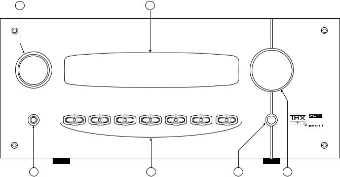
FRONT PANEL
6 |
|
|
|
5 |
|
|
|
|
|
B&K Components, Ltd. |
AVR 507 |
|
|
|
|
|
A/V Receiver |
|
|
SOURCE |
|
|
|
|
|
|
|
|
|
|
|
|
|
|
|
||||
HEADPHONE |
SLEEP |
PRESET |
ENTER |
DOWN |
UP |
MODE |
MENU |
|
|
|
|
|
|||||||
|
|
|
|
|
|
|
|
L U C A S F I L M |
E X T E N D E D |
|
|
|
|
|
|
|
POWER |
|
S U R R O U N D |
|
|
|
|
|
|
|
|
|
|
|
|
|
|
|
|
|
ON/OFF |
|
1 |
|
|
|
|
|
|
|
|
|
|
1 |
|
|
|
2 |
|
|
3 |
4 |
|
1.Headphone Jack - Stereo headphones having a standard ¼ inch binaural plug can be connected to the headphone output. The receiver must be on and in HEADPHONE Mode for proper headphone operation.
2.Front panel buttons
|
|
|
|
|
|
SLEEP |
|
Puts the receiver in standby (low power) mode. |
|
|
PRESET |
|
Steps through audio / video presets for instant recall of setups. |
|
|
|
Pressing ENTER recalls the preset. |
|
|
|
|
|
|
|
|
ENTER |
|
Confirm selection or display current status of the receiver. |
|
|
DOWN |
|
Step through menus and audio modes. |
|
|
UP |
|
Step through menus and audio modes. |
|
|
MODE |
|
Steps through the audio modes. |
|
|
MENU |
|
Enter / exit menu system |
|
|
|
|
|
|
3.Main power switch - Removes all power to the receiver. Normal operation of the receiver requires the power switch to remain on. Use the Sleep button for daily on and off of the receiver. It places the unit in standby mode that allows turning back on with the remote control. Turn the receiver off with the main power switch when not using the receiver for an extended period of time.
4.Volume control - For controlling system volume. Turning the encoder-type volume control clockwise increases the volume level, counterclockwise decreases the volume level. The volume knob is also used to change other receiver settings. See THE MENU SYSTEM and OPERATION
5.Display - The receiver display is a 16 character alphanumeric fluorescent display. Displays current status of receiver and any changes being performed.
6.Source - For controlling source selection. Turning the encoder-type selector clockwise or counterclockwise will navigate through the selection of all input sources and the AM and FM tuner.
9

REAR PANEL
21 |
20 |
|
19 |
|
18 |
|
|
17 |
|
|
16 |
15 |
|
14 |
|
|
|
|
13 |
|
|
|
|
12 |
|
11 |
B&K |
|
C O A X D I G I T A L |
|
|
|
O P T I C A L D I G I T A L |
|
|
|
|
|
|
|
|
|
|
|
|
|
|
|
C O M P O N E N T V I D E O |
|
|||
Z A O U T |
T V |
V 2 |
V 1 |
O U T |
S A T |
C D |
D V D |
V 2 |
V 1 |
Z A |
Z B |
Z B / V 2 |
V 1 |
T A P E |
T A P E |
S A T |
C D |
D V D |
T V |
V 2 |
V 1 |
I N 1 |
I N 2 |
I N 3 |
O U T |
|
SIMPLY BETTER! |
|
|
|
|
|
|
|
|
|
|
|
|
|
|
|
|
|
|
|
|
|
|
|
|
|
|
C A U T I O N |
|
|
|
|
|
|
|
|
|
|
|
|
|
|
|
|
|
|
|
|
|
|
|
|
|
|
R I S K O F E L E C T R I C S H O C K |
|
|
|
|
|
|
|
|
|
|
|
|
|
|
|
|
|
|
|
|
|
|
|
|
|
|
D O N O T O P E N |
|
|
|
|
|
|
D V D - A U D I O I N |
Z A A U D I O O U T |
|
|
|
|
|
|
|
|
|
|
|
|
|
|
|
|
||
|
|
|
|
|
|
|
|
|
|
|
|
|
|
|
|
|
|
|
|
|
|
|
||||
|
|
|
|
|
|
|
S U B |
C E N T E R |
S U B |
C E N T E R |
|
|
|
|
|
|
A u d i o / V i d e o S y s t e m s M a d e i n t h e U . S . A . |
|
|
|
|
|
||||
S E R I A L # |
Z B O U T |
S A T |
C D |
D V D |
|
|
|
|
|
|
|
|
|
|
|
|
|
|
|
|
|
|
|
|
|
|
|
|
C O N T R O L O U T |
I R I N |
|
|
|
|
|
|
|
|
|
|
|
|
|
|
|
|
|
|
|
|
|
|
|
|
|
1 1 2 V D C |
2 |
Z A |
R S - 2 3 2 |
|
|
|
|
|
|
|
|
|
|
|
|
|
|
|
|
|
|
|
|
|
|
|
5 0 m A |
|
|
|
|
|
|
|
|
|
|
|
|
|
|
|
|
|
|
|
|
|
|
|
|
|
|
|
|
|
|
|
|
|
|
|
|
|
|
|
|
|
|
|
|
|
|
|
|
|
|
|
|
+ |
|
|
|
|
|
|
|
|
|
|
|
|
www.bkcomp.com |
||
I E E E |
|
|
|
|
|
|
|
|
|
|
|
|
|
|
|
|
1 3 9 4 |
|
|
|
|
|
|
|
|
|
|
|
|
|
|
|
|
E X P A N S I O N |
|
|
|
|
|
|
|
|
|
|
|
|
|
A M |
F M |
|
3 |
4 |
Z B |
S U R R |
F R O N T |
S U R R |
F R O N T S B A C K |
L I N E O U T P U T S |
|
L I N E I N P U T S |
|
|
A N T E N N A |
||||
|
B & K C o m p o n e n t s , L t d . |
|
Manufactured under license from Dolby Laboratories. |
|
|
Manufactured under license from DTS Technology LLC. |
|
|
B&K Components, Ltd. |
|||||||
|
|
"Dolby", "Pro Logic" and the double-D symbol are trademarks of Dolby Laboratories. |
|
Additionally licensed under the following US Patent 5,451,942 & National Patent applications derived from PCT/US95/00959 |
|
|||||||||||
A u d i o / V i d e o S y s t e m s - M a d e i n t h e U . S . A . |
|
|
|
2100 Old Union Rd - Buffalo, New York 14227 |
||||||||||||
Confidential Unpublished Works. 1992-1997 Dolby Laboratories, Inc. All rights reserved. |
Additional U.S. And Foreign Patents pending. "DTS", "digital surround", and "coherent acoustics" logos are trademarks of DTS Technology LLC. All rights reserved. |
|||||||||||||||
F U S E |
|
|
|
|
||||||||||||
C A U T I O N : F O R C O N T I N U E D |
S U R R O U N D L E F T |
S U R R O U N D R I G H T |
|
C E N T E R |
S U R R O U N D B A C K L E F T |
S U R R O U N D B A C K R I G H T |
F R O N T L E F T |
F R O N T R I G H T |
||||||||
P R O T E C T I O N A G A I N S T R I S K |
|
|||||||||||||||
O F F I R E R E P L A C E O N L Y W I T H |
|
|
|
|
|
|
|
|
|
|
|
|
|
|
|
|
S A M E T Y P E A N D V A L U E F U S E |
|
|
|
|
|
|
|
|
|
|
|
|
|
|
|
|
|
P L U S |
M I N U S |
P L U S |
M I N U S |
|
P L U S |
M I N U S |
P L U S |
M I N U S |
P L U S |
M I N U S |
P L U S |
M I N U S |
P L U S |
M I N U S |
|
|
+ |
- |
+ |
- |
|
+ |
- |
+ |
- |
+ |
- |
+ |
- |
+ |
- |
|
- A C L I N E
1 |
2 |
3 |
4 |
5 |
6 |
7 |
8 |
9 |
10 |
The receiver’s back panel is organized into groups of inputs and outputs for audio and video as shown below. See back of this manual for an enlarged view.
1.AC fuse holder - Holds the AC Line fuse. Replace only with same type and value. Note: the voltage label located on the AC fuse holder cover plate.
2.AC input receptacle - For attaching the supplied AC power cord to the receiver.
3.IEEE 1394 input (optional) For future interface applications.
4.Control outs - Outputs that allow you to remotely control external devices. (See “Making The Connection“).
5.IR in - Accepts input from external IR receptors. Connect an IR repeater (“home run”) to IR IN for controlling the receiver. This method of control is useful when the front IR receptor is blocked (for example, by a cabinet door) or to control the receiver from another room. This input is typically used in place of an emitter attached to the front panel.
6.RS-232 input - Computer interface applications.
7.Speaker outputs - Connections for your speakers.
Red binding posts - speakers (+)
Black binding posts - speakers (-)
8. DVD Audio inputs - Connections for a DVD audio or other 5.1 source device. Red RCA jacks - right front and surround audio inputs White RCA jacks - left front and surround audio inputs Gray RCA jacks - center and sub audio inputs
9.Surround outputs - Variable level outputs for driving external power amplifiers or powered speakers.
10.Antenna inputs - Connections for the AM and FM antennas.
10
11. Component Video outputs - Switched output connections for your component video monitor.
Red RCA jack |
- typically connect to the red input on a component video monitor |
Green RCA jack |
- typically connect to the green input on a component video monitor |
Blue RCA jack |
- typically connect to the blue input on a component video monitor |
12. Component Video inputs - Switched input connections for three component video devices. |
|
Red RCA jack |
- typically connect to the red output of a component video source |
Green RCA jack |
- typically connect to the green output of a component video source |
Blue RCA jack |
- typically connect to the blue output of a component video source |
13. Line inputs - Connections from your audio/video sources. |
|
Red RCA jacks |
- right analog audio |
White RCA jacks |
- left analog audio |
Yellow RCA jacks |
- composite video |
4 pin din jacks |
- S-video |
14.Line level outputs - Fixed level outputs to an audio or video recorder.
15.Zone 2 outputs - Variable level outputs to your video monitors and external amplifiers.
16.Zone 1 outputs - Video outputs to your video monitors.
17.Optical Digital inputs - Optical digital inputs are used to connect digital audio signals from your source to the receiver. The incoming signal may be PCM, Dolby Digital or DTS.
18.Optical Digital output - Zone 1 optical output to carry digital information from the selected digital input of the receiver out to digital recorders, personal computers, etc.
19.Coax Digital inputs - Coax digital inputs are used to connect digital audio signals from your source to the receiver. The incoming signal may be PCM, Dolby Digital (AC-3) or DTS.
20.Coax Digital output - Independent Zone 1, and Zone 2, coax outputs to carry digital information from the selected digital input of the receiver out to digital recorders, personal computers, etc.
21.Expansion (optional) - For future format and interface applications.
The serial number of your unit is located above the expansion port.
11
MAKING THE CONNECTION
It’s tempting to just plug in your new A/V receiver and have great sound pour out. Before you do that, take a few minutes to plan out how you want the receiver to fit into your audio/video system. Ask yourself the following questions:
What source components do I want to connect to my receiver? (CD, VCR, etc.)
What equipment will be receiving the audio and video? (TV monitor, Speakers, etc.)
The answers to your questions determine how many cables you need to connect to the back of the receiver. Good preplanning equals great sound. Keep these recommendations in mind:
List all components in your system and indicate which jacks of the receiver each component will be connected to. Your receiver has seven sets of inputs. It is convenient to connect a DVD player to the input labeled DVD or a VCR to the input labeled V1 or TAPE, etc. However, your equipment may differ from the labeling on the back of your receiver. In most cases you can connect any type of source to any input (see FREQUENTLY ASKED QUESTIONS). For example, if you don’t have a satellite receiver you can connect a DAT player or a second cassette deck to SAT. You can also reprogram the source name that will appear on your receiver’s front panel and on-screen display (see SYSTEM SETUP - INPUTS)
Also note the length of the cable for each component’s connection and describe how it should be routed or draw your routing scheme below your list. You may want to label each cable with a name or number at both ends. Use high quality connections to maintain high quality audio and video.
Think about the type and length of cable you need and obstacles in the cable’s path (doorways, furniture, walkways, etc.). To decide which ones are right for you talk to your dealer about the various cable products that are available.
For safety, keep all cables out of high traffic areas (hallways or doorways) and away from equipment that radiates power, including amplifiers, power cords, heaters, etc.
If you might expand your audio/video system later, keep these ideas in mind as you plan current cable runs.
To provide the best tuner reception, make sure the antenna is at least several feet away from the receiver and any other equipment that may produce high frequency interference such as Personal computers, CD players, halogen lamps, etc.
Take a look at the back panel of the receiver. You will notice that the RCA-type audio input and output connectors are identified by colors, red for right channel and white for left channel audio. Red/White/Grey identifies the surround outputs. Red/Green/Blue identifies component video input and output connectors. Composite video input and output connectors are identified by yellow. Coaxial digital inputs are identified by orange.
12
AUDIO / VIDEO CONNECTIONS
Connecting your analog sources to your receiver
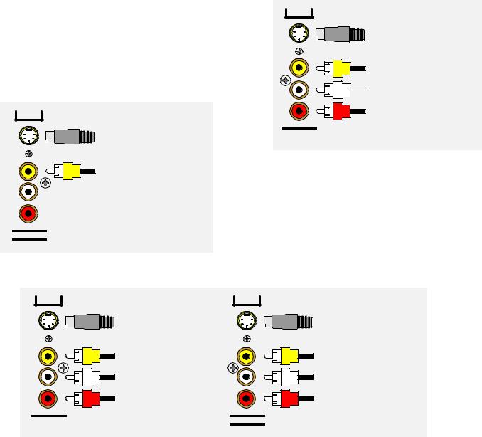
Audio / Video source - connecting a DVD/VLD player to the receiver’s analog inputs. Use the same instructions for connecting to other audio / video sources such as a satellite receiver, cable box, etc. See Connecting Video for use with other than composite and S-video (Omit the video connections for an audio-only component such as a CD player.)
Attach one end of the audio interconnect cable to the left audio output on the DVD/VLD player, then attach the other end to the left (white) DVD/VLD audio input on the receiver. Repeat for the right (red) audio connection. Attach one end of the composite video interconnect cable to the video out on the DVD/VLD player, then attach the other end to the yellow video input on the receiver labeled DVD/VLD. Repeat for the S-video connections if you are using S-video.
ZA
S-Video output to monitor input
DVD
S-Video input from DVD output
Composite video input
from DVD output
Left audio input from

 DVD output
Right audio input from DVD output
LINE INPUTS
S BACK
Composite video output to monitor input
Video Monitor - Attach one end of the composite video interconnect cable to the video input on the monitor, then attach the other end to the yellow video output on the receiver’s ZONE OUTPUTS. Repeat for the S-video connections if you are using S-video. Dual zone operation requires connections be made to (ZA) for Zone 1 (A), and (ZB) for Zone 2 (B).
VCR or audio recorder - connect a VCR to V1. Use the same instructions for connecting to the V2 and TAPE analog inputs. If connecting a cassette deck or other audio-only recorder then omit the video connections.
V1 |
V1 |
S-Video output |
S-Video input |
to VCR input |
from VCR output |
Composite video output |
Composite video input |
to VCR input |
from VCR output |
Left audio output |
Left audio input |
to VCR input |
from VCR output |
Right audio output |
Right audio input |
to VCR input |
from VCR output |
LINE OUTPUTS |
LINE INPUTS |
Attach one end of the audio interconnect cable to the left audio output on the VCR, then attach the other end to the left (white) V1 audio input on the receiver. Repeat for the right (red) audio connection. Attach one end of the composite video interconnect cable to the composite video output on the VCR, then attach the other end to the yellow video input on the receiver labeled V1. Repeat for the S-video connections if you are using S-video.
Attach one end of the audio interconnect cable to the left audio input on the VCR, then attach the other end to the left (white) V1 audio output on the receiver. Repeat for the right (red) audio connection. Attach one end of the composite video interconnect cable to the composite video input on the VCR, then attach the other end to the yellow video output on the receiver labeled V1. Repeat for the S-video connections if you are using S-video.
13
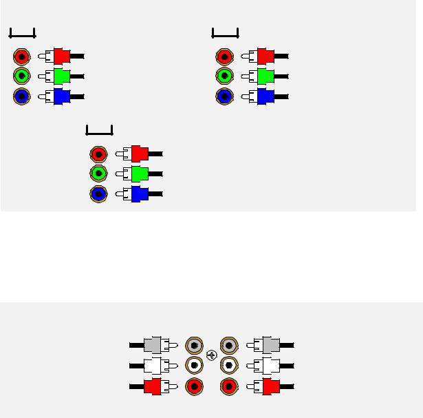
Component Video - in addition to S-video and composite video switching, your receiver provides three sets of component video inputs for DVD and TV/DBS type inputs, and one set of component video outputs. Your receiver’s component video connections are passive to minimize the possibility of video format compatibility issues. Use the same instructions to connect a second and third (TV/DBS) component video device.
COMPONENT VIDEO
IN 1 |
IN 2 |
Component video input to |
Component video input to V1 |
DVD red output |
red output |
Component video input to |
Component video input to V1 |
DVD green output |
green output |
Component video input to |
Component video input to V1 |
DVD blue output |
blue output |
OUT
Component video output to the video monitor's red input
Component video output to the video monitor's green input
Component video output to the video monitor's blue input
Attach one end of a video interconnect cable to the red video output on the DVD, then attach the other end to the red component video input (IN 1) connector on the receiver. Repeat for (green) and (blue) video connections. Repeat for the other (TV/DBS) component source device using component video input (IN 2). Repeat similar to the previous two cases for the remaining third component source device. Attach one end of a video interconnect cable to the red component video output (OUT) on the receiver, then attach the other end to the red video input on the video monitor. Repeat for (green) and (blue) video connections.
DVD Audio - connect a DVD Audio or other 5.1 surround format device, to the receiver’s DVD Audio input.
DVD AUDIO IN
SUB CENTER
Connect to the DVD audio player Subwoofer output
Connect to the DVD audio player Left Surround output
Connect to the DVD audio player Center output
Connect to the DVD audio player Left Front output
Connect to the DVD audio |
Connect to the DVD audio |
player Right Surround output |
player Right Front output |
SURR |
FRONT |
Attach one end of an audio interconnect cable to the center output on the DVD Audio source device, then attach the other end to the FRONT center (gray) DVD Audio input on the receiver. Repeat for the front left (white) and front right (red) audio connection. Attach one end of an audio interconnect cable to the sub output on the DVD Audio source device, then attach the other end to the SURR subwoofer (gray) DVD Audio input on the receiver. Repeat for the surround left (white) and surround right (red) audio connection.
14
DIGITAL CONNECTIONS
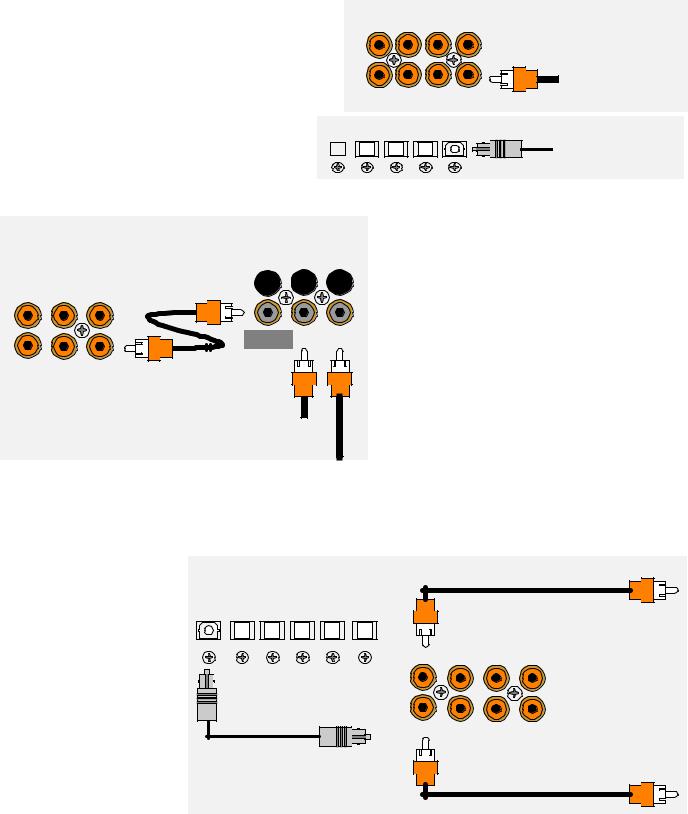
Connect digital inputs (DVD, VLD, etc.) to the receiver. You will need either coaxial or optical digital inputs to play Dolby Digital (AC-3) or DTS surround sound processing. Digital connections are also recommended for PCM sources. If your source has both optical and coaxial outputs connect only one.
Coaxial digital inputs - standard RCA type connectors. Attach one end of your digital coaxial cable to your source coaxial digital out and the other end to the appropriate receiver coaxial digital (orange) input.
Optical digital inputs - First, remove the cap on SA
the optical digital input. Save the cap. Attach one |
|
T |
|
end of your digital optical cable to your source and |
|
|
|
|
|
|
|
the other end to the appropriate digital input on the |
|
|
|
back of the receiver. |
|
|
|
COAX DIGITAL |
V1 |
|
ZA OUT TV |
V2 |
|
ZB OUT SAT CD DVD
OPTICAL DIGITAL
CD DVD V2 V1
Coax digital input from DVD output
Optical digital input from source output
|
|
|
|
|
Connecting A Laser disc Player - Dolby Digital |
|
|
|
DT-1 |
|
(AC-3) laser discs use a special technique called AC- |
|
|
|
|
|
3 RF to encode the Dolby Digital bitstream. If the |
|
COAX DIGITAL |
|
|
laser disc player is capable of playing back Dolby |
|
|
|
|
Digital discs it will have a separate output for this |
||
TV |
V2 |
V1 |
|
|
|
|
|
|
|
|
bitstream in addition to the normal coaxial and/or |
|
|
MAIN |
COAX |
AC-3 RF |
optical outputs. Do not connect the AC3-RF output |
|
|
directly to your receiver. The AC-3 RF bitstream |
|||
|
|
OUTPUT |
INPUT |
INPUT |
|
|
|
|
|
|
must first be converted to a normal (non-RF) Dolby |
SAT |
CD |
DVD |
|
|
Digital type signal. It is recommended that a B&K |
|
|
Coax digital input |
|
DT-1 be used to convert and select between the |
|
|
|
|
Laser’s AC-3 RF and PCM/DTS signals. The output |
||
|
|
from VLD output |
|
from a DT-1 will automatically select between the |
|
|
|
AC-3 RF input |
connected PCM/DTS bitstreams and the converted |
||
|
|
AC-3 RF Dolby Digital signal. Other AC-3 RF to |
|||
|
|
from VLD output |
|||
|
|
|
|
|
Dolby Digital decoders may not make this switch |
automatically. Connect the laser disc’s AC3-RF output to the DT-1’s AC-3 RF input. Connect either the laser disc player’s PCM coaxial or optical digital output (not both) to the DT-1’s coaxial or optical input. Connect the DT-1’s coaxial output to the desired coaxial digital input on your receiver.
Digital Outputs |
- |
Separate |
|
|
|
|
|
|||||
and independent coax digital |
|
|
|
|
|
|||||||
outputs |
are |
available |
for |
|
|
|
|
|
||||
Zone 1 and Zone 2. Connect |
OPTICAL DIGITAL |
|
Zone 1 (A) Coax digital output |
|||||||||
to |
a |
digital recorder (CD-R, OUT |
SAT CD DVD V2 |
V1 |
||||||||
mini |
disc, |
DAT, |
personal |
|
|
to digital recorder |
||||||
computer, etc.) These signals |
|
|
COAX DIGITAL |
|
||||||||
are the same as the incoming |
|
ZA OUT |
TV |
V2 |
V1 |
|||||||
digital |
signal |
from |
the |
Zone 1 (A) Optical digital output |
|
|
|
|||||
selected |
source |
on |
each |
|
|
|
||||||
to digital recorder |
|
|
|
|
||||||||
zone. If your digital recorder |
|
|
|
|
||||||||
|
|
|
|
|
||||||||
has both optical and coaxial |
|
ZB OUT |
SAT |
CD |
DVD |
|||||||
inputs you need only connect |
|
|||||||||||
|
|
|
|
|
||||||||
one. Zone 1 selected digital |
|
|
Zone 2 (B) Coax digital output |
|||||||||
input |
is |
converted |
to |
both |
|
|
||||||
|
|
to digital recorder |
||||||||||
coaxial and optical. You may |
|
|
||||||||||
|
|
|
|
|
||||||||
connect |
one |
digital |
recorder |
|
|
|
|
|
||||
to |
the |
optical |
output |
and |
|
|
|
|
|
|||
another recorder to the coaxial. Zone 2 digital output is coax.
15
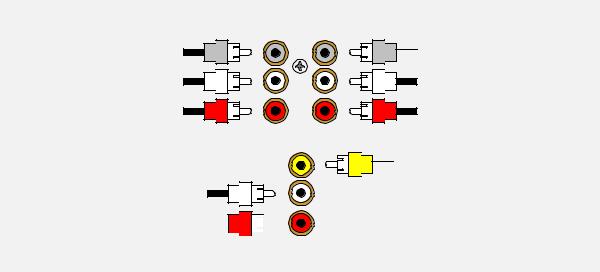
SURROUND OUTPUTS
Your receiver has multiple surround processor outputs for use with external amplifier(s) or powered speakers. The AVR 505 receiver allows THX Surround EX compatibility via two Surround Back ‘S BACK’ processor outputs.
Here is a typical surround output setup:
Connect to the Subwoofer 'SW' power amplifier input
Connect to the Surround Left 'Sl' power amplifier input
Connect to the Surround Right 'Sr' power amplifier input
Connect to the Surround Back Left 'Sbl' power amplifier input
ZA AUDIO OUT
SUB CENTER
Connect to the Center power
 amplifier input
Connect to the Left Front power amplifier input
Connect to the Right Front
power amplifier input
SURR FRONT
Connect to Zone 1 (A)  composite video monitor input
Connect to the Surround Back Right 
 'Sbr' power amplifier input

S BACK
Subwoofer Output - Connect an RCA cable from the receiver’s SW output (part of the surround outputs. If your subwoofer does not contain its own amplifier (powered subwoofer) you will need to acquire the use of an external power amplifier. Connect the external amplifier’s speaker output to your subwoofer.
16
SPEAKER OUTPUTS
L C R
FRONT |
(-) (+) |
|
FRONT |
LEFT |
|
CENTER |
RIGHT |
|
|
|
|
(-) (+) |
|
|
(-) (+) |
SURROUND LEFT SURROUND RIGHT |
CENTER |
SURROUND BACK SURROUND BACK |
FRONT LEFT |
FRONT RIGHT |
|||
LEFT |
RIGHT |
||||||
|
|
|
|
|
|||
PLUS |
PLUS |
PLUS |
PLUS |
PLUS |
PLUS |
PLUS |
|
MINUS |
MINUS |
MINUS |
MINUS |
MINUS |
MINUS |
MINUS |
|
Sl |
Sr |
(-) (+) |
(-) (+) |
Sbl |
Sbr |
(-) (+) |
(-) (+) |
SURROUND |
SURROUND |
LEFT |
RIGHT |
SURROUND |
SURROUND |
BACK LEFT |
BACK RIGHT |
Five-way binding posts are provided, one pair for each channel. They are designed to accept a banana-type plug or spade lug connector (shown below) and are color coded for easy identification. The red (+) post should always be connected to the speaker’s red (+) jack. The black (-) post should always be connected to the speaker’s black (-) jack.
Spade connector Banana jack
The amplifier section of the receiver will produce 150 watts / channel into 8 ohms. See SPECIFICATIONS for more information. Here is a typical receiver output setup:
17
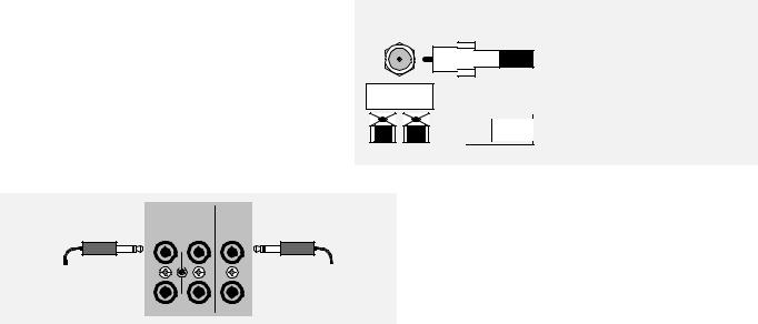
ANTENNA CONNECTIONS
The FM jack is a standard screw on F-type connector. The AM is a push type. Strip ¼ inch of insulation off your AM antenna wires and insert one wire end into each hole while holding the tabs down. Release the tabs to lock in the AM antenna wires.
CONTROL OUTPUTS / IR INPUTS
TUNER |
|
FM antenna |
FM Antenna Input |
|
|
|
from Indoor/Outdoor Antenna, |
|
Cable Box, etc. |
 AM Antenna Input
 from Loop Antenna
AM antenna
1 |
2 |
ZA |
CAUTION! |
CONTROL OUT |
IR IN |
|
|
+12VDC |
|
|
|
|
50mA |
|
|
3.5 mm control output |
|
|
3.5 mm IR in |
to amplifier, etc. |
|
|
from remote repeater |
3 |
4 |
ZB |
|
Control Outputs - These connections are used for controlling other equipment such as an external B&K Components, Ltd. amplifier, projection screen, etc. Connect your control cable to the receiver using a mono 3.5 mm jack shown at left. The plug must be wired as tip (+) and the long barrel section (-).
The Control outputs are programmable for each source in your system (see “Advanced Setup”). However, the receiver provides the following factory preprogrammed setup that should serve for most standard system applications.
Control 1 - HEADPHONE. On (+12 VDC) when Zone 1 is on and not in Headphone mode, off when Zone 1 is off or in Headphone Mode. This mode may be used for controlling external amplifiers or powered subwoofers in Zone 1.
Control 2 - Zone 2. On (+12 VDC) when Zone 2 is on, off (0 VDC) when Zone 2 is off. This mode is used for controlling external amplifiers, projection screens, etc. in Zone 2.
Control 3 - Z1 + Z2. On (+12 VDC) when Zone 1, Zone 2, or both zones are turned on. Off (0 VDC) when both zones are off.
Control 4 -REMOTE. It will repeat a received 38 kHz modulated IR signal. The receiver will transmit received IR signals even in sleep mode.
Note - The control outputs can output a maximum of 50 mA. Check to see that the source you are connecting to the control out requires 50 mA or less current.
WARNING - Not all manufacturers adhere to the +12 VDC control specification. Check to see if your sources control inputs are +12 VDC compatible. Do not connect your receiver’s control outputs to a source with control or remote inputs rated at +5 VDC or other voltage rating. Damage to your source may result.
IR Inputs - Your receiver can be controlled by a directly connected IR repeater system in combination with or in place of the supplied remote control. Connect your IR input cable to the receiver using a mono 3.5 mm jack shown above. The plug must be wired as tip (+) and the long barrel section (-). The inputs are standard 38kHz modulated IR type with a voltage range of +5 to +12 VDC.
18
FREQUENTLY ASKED QUESTIONS
My collection of equipment differs from the labels on the back of my receiver, how can I hook them up?
Your receiver provides 5 identical sets of inputs - V1, V2, DVD, CD, and SAT. Each of these has analog audio, composite video, S-video, coaxial digital audio, and optical digital audio. It is convenient to connect components as labeled on the back of your receiver, but since all the inputs are identical, you can connect any compatible source to any set of inputs. For example, you can connect a DAT player to V1 instead of a VCR. You can program your receiver to display any 5 character name for any input (see System Setup - Inputs).
The sixth input, TV, is identical to the others except that there is no optical digital. You can also connect portables to any other coaxial digital input using adapters or special cables. If you have a source with only optical digital output don’t connect it to TV.
The seventh input, TAPE, has analog audio, composite video and S-video, but has no digital inputs. It is primarily intended for analog recorders such as VCRs or cassette decks. If you have a three-head cassette or reel-to-reel tape deck you will prefer the TAPE input since it allows a full tape monitor capability. Tape monitor allows you to listen to what is actually on the tape as you are recording it. The V2 input also provides full tape monitor capabilities for Zone 2. If you don’t use Zone 2 you can use V2 as a second independent analog tape monitor loop. V1 includes a line level output but does not provide true tape monitor capability.
My DVD player (or other source) has both optical and coaxial digital outputs. Should I connect both?
No, connect only one digital cable per source.
Do I need an AC-3 RF demodulator (B&K DT-1 or equivalent) to playback Dolby Digital DVDs?
No, this is required only for Dolby Digital laser discs.
Do I need an AC-3 RF demodulator (B&K DT-1 or equivalent) to playback DTS laser discs?
No, this is required only for Dolby Digital laser discs.
Do I need to connect both analog and digital audio from my DVD player (or other digital audio source) to the receiver?
In general, it is simpler to connect both. However, if you can meet all of the following criteria you need only connect digital:
1.I do not use Zone 2. (Zone 2 is analog only - if you use Zone 2 you must connect both left and right analog to hear audio.)
2.I do not own any old laser discs. (Early laser discs contained only analog audio tracks - you must connect both left and right analog audio to play these back.)
3.I do not use Tape Monitor. (It is possible to tape digital-only sources. However, if you wish to listen directly to the tape as you are recording - you must connect both left and right analog audio - the tape monitor loops are strictly analog.)
If the tape monitor loop is strictly analog, how do I make an analog recording of a digital-only source?
Do not select TAPE. Select the source you wish to record. Select STEREO 9, the LtRt mode. If that source is digital, the converted digital-to-analog will appear at the tape and V1 outputs. V2 out, like Zone 2 out, is analog only. (See Operation - Audio Mode.)
I want to make direct digital recordings from my CD player (or other digital source) on my CD Recorder, DAT (or other digital recorder). Can my receiver make this connection for me?
Yes, your receiver’s digital outputs act much like the analog tape outputs. When you select a source, if that source has a digital connection to your receiver, then that digital signal will appear on the receiver’s coaxial and optical digital outputs. Simply connect all of your sources digital outputs to your receiver’s digital inputs. You can then connect up to three digital recorder inputs to your receiver’s three digital outputs.
19
My laser disc player (or other digital source) has only optical output, but my CD recorder (or other digital recorder) has only coaxial input. Do I need some sort of converter to make direct digital recordings?
No, your receiver will convert optical to coaxial and coaxial to optical. The currently selected digital input (optical or coaxial) will appear at both of the receiver’s digital outputs (optical and coaxial).
Do I need to connect both analog and digital audio from my receiver to my CD, DAT, MD, etc. recorder?
In general, yes. If all of the sources you wish to record are digital, then you need only connect digital to your recorder. However, your receiver does not provide digital outputs for non-digital inputs. If you wish make a digital recording from an analog-only source you must also connect analog from your receiver (Tape or V1 out) to your recorder.
Can I connect a phonograph directly to my receiver?
No, you will need a separate outboard phono preamplifier. The output of the phono preamp can then be connected to any analog input on your receiver. We recommend our Phono 10 phono preamp. In addition to its superb analog audio processing, it has an option for S/PDIF coax output. Talk to the dealer where you purchased your receiver.
Do I need to connect both S-video and composite video to my receiver?
If all of your video equipment has S-video then you need only connect S-video. S-video is a higher quality video format and you will probably not want to use composite. If all or most of your video equipment is composite then it is simplest to just connect the composite and omit S-video.
Can I connect mixed composite and S-video sources?
Yes, but your receiver will not convert S-video to composite or composite to S-video. If your monitors and VCRs accept only composite video then there is no point in connecting S-video from other sources. If you use mixed S-video and composite sources you must connect both S-video and composite to your monitors and VCRs. You will need to change your monitor or VCR S-video / composite inputs manually when you change sources. This can normally be done via the monitor’s or VCR’s remote control (or the supplied universal remote). Some monitors or VCRs may require you to physically disconnect S-video before they will accept composite video. Some monitors are capable of automatic switching between S-video and composite. Your receiver must be setup properly in order to work with auto switching monitors - refer Setup Displays.
To assist you, the receiver’s on-screen display will tell you what video is currently selected whenever you change sources or hit the SEL (remote) or ENTER (remote or front panel) key, but it cannot switch your monitor or VCR input for you. If you are watching S-video, but the source is composite video only, you will see “Switch Monitor to Composite” on your Monitor. If you are watching Composite video but your source is S-video only, you will see “Switch Monitor to S-video” on your monitor. These displays appear only if your receiver is setup for manual monitors.
Can I connect mixed composite and S-video monitors and VCRs?
Yes, but you must connect both S-video and composite from all of your sources - your receiver will not convert between S-video and composite. Refer to the previous question if not all of your sources have both S- video and composite outputs.
For example, it is common to have an S-video monitor and a composite VCR. Connect the monitor to the Zone 1 S-video and composite outputs and the VCR to the V1 or TAPE composite output. The composite inputs will appear at the composite outputs for TAPE and V1. (The S-video inputs also appear at the TAPE and V1 S- video outputs, but, in this example, they are not connected.) To prevent feedback, TAPE IN will not appear on TAPE OUT and V1 IN will not appear on V1 OUT - this also applies to the audio outputs. Zone 2 works the same for Zone 2 OUT and V2 OUT with feedback prevention on V2.
Things get a bit more complicated for the Zone 1 output because it contains your receiver’s internal onscreen display system. You must be sure that you tell your receiver if you have a monitor which can automatically switch between S-video and composite outputs, or one which must be manually switched (see Setup Displays).
20
SETUP
For best results, perform the following set up procedure when you initially install your receiver and anytime you change or add sources, speakers, etc. or when you rearrange your listening area
THE MENU SYSTEM
Setup of your receiver will require you to navigate through the menu system. We recommend that you use a video monitor connected to the Zone 1 output along with the remote control provided with your receiver. It is also possible to set up your receiver from the front panel. Do not leave your video monitor on with the receiver in the menu system for long periods of time. This can result in permanently burning the menu display into your monitor’s screen. This would take several hours so there is no danger of it happening during normal setup procedures. The following are general instructions for using the menu system. A complete guide to the menu system is included at the back of this manual.
MENU - If you are not already in the menu system, the MENU button will activate the menu system. Once you are in the menu system, the MENU button will return you to the next higher-level menu or, if you are already at the highest level, it will exit from the menu system.
UP/DOWN ARROWS - Once you are in the menu system, use the UP/DOWN ARROWS to move to the desired menu selection. The currently active menu line is highlighted in a contrasting color.
SEL (remote) or ENTER (remote or front panel) - Some menu selections cause another menu to be activated. Use the UP/DOWN ARROWS to move to the desired menu line. Pressing SEL or ENTER will activate the next menu.
NUMERIC KEYS (remote only) - From the remote control you may also go directly to a menu line by typing the corresponding line number. If there is another menu below that line it will be activated immediately (no ENTER required).
LEFT/RIGHT ARROWS (remote) or VOLUME KNOB (front panel) - Some menu selections allow you to change one of the receiver settings. Use the UP/DOWN ARROWS to move to the desired menu line. Pressing the LEFT/RIGHT ARROWS will change the setting. There are no LEFT/RIGHT ARROWS on the front panel. While in the menu system, the VOLUME KNOB acts as the LEFT/RIGHT ARROWS. This means that you will not be able to adjust the volume from the front panel while in the menu system. The remote control volume will work in most menus.
TEXT EDITING - some menu selections will require you to edit text. Use the UP/DOWN ARROWS to change the current (blinking) character. Use the LEFT/RIGHT ARROWS (or VOLUME KNOB) to move to another character position. Additionally, while in the edit text mode, a successive press of a numeric key allows selecting between numbers, letters and/or symbols. The selection options for each of the numeric keys are as follows:
0 [-, +, /, ?, space]; 1 [A, B, C, a, b, c]; 2 [D, E, F, d, e, f]; 3 [G, H, I, g, h, i]; 4 [J, K, L, j, k, l]; 5 [M, N, O, m, n, o]; 6 [P, Q, R, p, q, r]; 7 [S, T, U, s, t, u]; 8 [V, W, X, v, w, x]; 9 [Y, Z, y, z].
EXIT (remote only) - From the remote control you may instantly EXIT the menu system.
UNIVERSAL REMOTE - Remember that when you press a source button (DVD, CD, etc.) the remote now controls the selected device. To return control to your receiver, you must press B&K or AUDIO. ALWAYS check that your remote is set to B&K or (AUDIO) before attempting to control your receiver. B&K or (AUDIO) will be displayed in the remote’s LCD window.
21
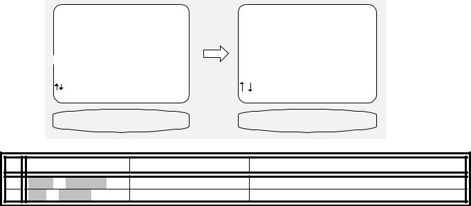
SYSTEM SETUP
You should always perform System Setup after first installing your receiver and after adding/changing speakers or sources or rearranging your listening area. Check that the remote is in B&K mode.
|
|
|
|
|
|
|
|
|
|
|
|
|
|
|
|
|
|
|
|
From Remote |
From Front Panel |
Action |
|
||||||||||
|
|
|
|
|
|
|
|
|
|
|
|
|
|
|
|
|
|
1 |
|
B&K |
or |
POWER |
|
|
SLEEP |
turn on receiver |
|
||||||
|
2 |
|
MENU |
|
|
|
|
|
MENU |
activate menu system |
|
|||||
|
3 |
|
À(UP) |
|
or |
§(DOWN) |
|
(UP) or (DOWN) |
move to System Setup |
|
||||||
|
4 |
|
SEL |
or |
ENTER |
|
(ENTER) |
activate SETUP SYSTEM |
|
|||||||
|
|
|
|
|
|
|
|
|
|
|
|
|
|
|
|
|
|
MAIN MENU |
|
|
SETUP SYSTEM |
|
1 |
Zone 1 |
Operation |
|
1 |
Speakers |
2 |
Zone 2 |
Operation |
|
2 |
Displays |
3 |
Zone 1 |
Favorite Presets |
3 |
Inputs |
|
4 |
Zone 2 |
Favorite Presets |
4 |
Presets |
|
5 |
System Setup |
5 |
Music Modes |
||
6 |
Memory Backup/Restore |
6 |
Advanced |
||
|
next item |
SEL select |
next item SEL select |
|
MENU |
exit menu system |
MENU main menu |
|
SYSTEM SETUP |
SETUP SPEAKERS |
|
|
From Remote |
From Front Panel |
Action |
1 |
À(UP) or §(DOWN) |
(UP) or (DOWN) |
move to Speakers |
2 |
SEL or ENTER |
(ENTER) |
activate SETUP SPEAKERS |
Speakers
The speaker’s menu lets you tell your receiver how many speakers you have in your system, the relative size of the speakers, and their location in the room. This is the most important setup procedure you will perform. The receiver comes from the factory setup for 7 small speakers and a subwoofer. If this does not match your speakers then audio information will be lost. For example, if you do not currently have a center channel speaker and you do not perform this setup procedure, the center channel information will be lost. If you perform this setup correctly, the receiver will know that you have no center channel speaker and send this information to your front left and right speakers (along with the normal front left and right information) so no audio information is lost.
Speaker Size
Speaker size generally refers to the size of your speakers. Audio material, particularly Dolby Digital and DTS movies, often contain large amounts of bass. If this bass information is sent to small speakers that are incapable of reproducing so much bass, then the bass information will be lost or distorted. TOO MUCH BASS MAY DAMAGE MANY SMALL SPEAKERS. By telling your receiver the size of your speakers, it will be able to intelligently route the bass to speakers that can reproduce it correctly. Typically, all bookshelf or satellite speakers are considered small. Smaller floor standing speakers with single woofers 8” or less should also be considered small. Floor standing speakers with 10” or larger woofers or multiple smaller woofers may be considered large. These are general guidelines only - if you are unsure consult your speaker manufacturer or check with the dealer if they are unsure. If you have all small speakers we strongly recommend use of a subwoofer. If your front left and right speakers (or more) are large then you may not require a subwoofer, but you may still get better results using a subwoofer, especially with Dolby Digital and DTS movies. All THX certified speakers are small, regardless of their physical size, and should be used in audio systems along with a subwoofer.
22
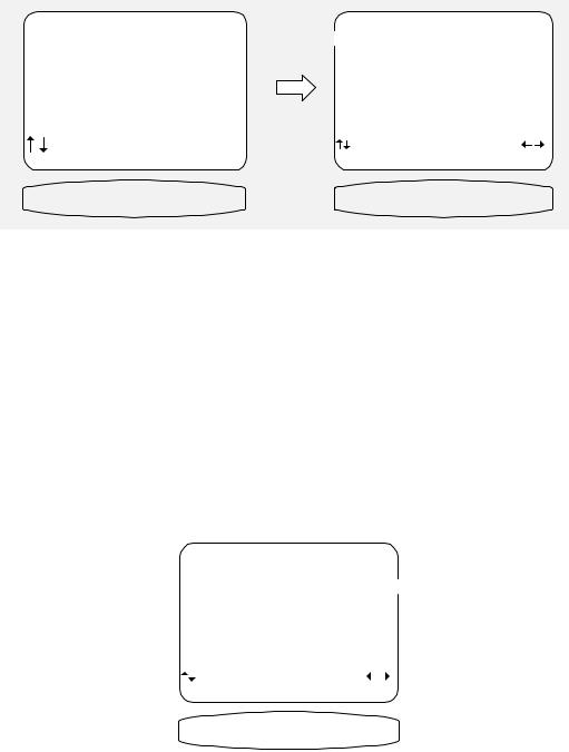
Set the size for your front left and right, ‘L’ and ’R’ speakers - You must have front speakers.
|
SETUP SPEAKERS |
|
|
SETUP SPEAKER SIZE |
|
1 |
Speaker Size |
|
1 |
Front |
Large |
2 |
Speaker Location |
|
2 |
Center |
Small THX |
3 |
Speaker Levels |
3 |
Surround |
Small THX |
|
4 |
Crossovers + LFE |
4 |
Surround Back |
None |
|
5 |
Room Equalization |
5 |
Subwoofer |
Yes THX |
|
|
|
6 |
THX Ultra 2 Sub |
Yes |
|
next item |
SEL select |
next item |
adjust |
MENU setup system |
MENU setup speakers |
||
SPEAKERS SIZE |
FRONT Large |
||
|
|
|
|
|
|
|
|
|
|
|
|
|
|
|
|
|
|
|
|
|
|
|
|
|
|
|
|
|
|
|
|
|
|
|
|
|
|
|
|
|
|
|
From Remote |
|
From Front Panel |
|
|
Action |
|
|
|
|
|
|
|
|
|||||||||||||||||||||
|
|
|
|
|
|
|
|
|
|
|
|
|
|
|
|
|
|
|
|
|
|
|
|
|
|
|
|
|
|
|
|
|
||||||
|
1 |
|
|
À(UP) |
or |
§(DOWN) |
|
|
|
(UP) or (DOWN) |
|
|
move to Speaker Size |
|
|
|
||||||||||||||||||||||
|
2 |
|
|
SEL |
or |
ENTER |
|
|
|
(ENTER) |
|
|
|
|
activate SETUP SPEAKER SIZE |
|
||||||||||||||||||||||
|
3 |
|
|
À(UP) |
or |
§(DOWN) |
|
|
|
(UP) or (DOWN) |
|
|
move to Front |
|
|
|
||||||||||||||||||||||
|
4 |
|
|
¶(LEFT) |
or |
•(RIGHT) |
|
|
VOLUME KNOB |
|
|
choose speaker size |
|
|
|
|||||||||||||||||||||||
|
|
|
|
|
|
|
|
|
|
|
|
|
|
|
|
|
|
|
|
|
|
|
|
|
|
|||||||||||||
|
|
|
|
|
|
|
|
|
|
|
|
|
|
|
|
|
|
|
|
|
|
|
|
|
|
|||||||||||||
|
Front setting |
|
|
|
|
|
Subwoofer Ultra |
|
|
|
|
Subwoofer Yes THX |
|
|
|
|
Subwoofer None |
|
||||||||||||||||||||
|
|
|
|
|
|
|
|
|
|
|
|
|
|
|
|
|
|
|
|
|
|
|
|
|
|
|
|
|||||||||||
|
Small |
|
|
|
|
|
|
|
|
Front Bass to SW |
|
|
|
|
Front Bass to SW |
|
|
|
|
Front Bass lost |
|
|||||||||||||||||
|
THX |
|
|
|
|
|
|
|
|
|
Front Hi-Pass to Front |
|
Front Hi-Pass to Front |
|
|
|
|
*Front Hi-Pass to Front only |
|
|||||||||||||||||||
|
Large |
|
|
|
|
|
|
|
|
Front Bass to SW |
|
|
|
|
Front Full Range to |
|
|
|
|
Front Full Range to Front |
|
|||||||||||||||||
|
|
|
|
|
|
|
|
|
|
|
|
Front Full Range to Front |
|
Front |
|
|
|
|
|
|
|
|
|
|
|
|||||||||||||
|
|
|
|
|
|
|
|
|
|
|
|
|
|
|
|
|
|
|
|
|
|
|
|
|
|
|
|
|
|
|
|
|
|
|
|
|
|
|
Set the size for your center ‘C’ speaker - |
|
|
|
|
|
|
|
|
|
|
|
|
|
|
|
|||||||||||||||||||||||
|
|
|
|
|
|
|
|
|
|
|
|
|
|
|
|
|
|
|
|
|
|
|
|
|
|
|
|
|
|
|
|
|
|
|||||
|
|
|
|
|
|
|
|
|
|
|
|
|
|
|
|
|
|
|
|
|
|
|
|
SETUP SPEAKER SIZE |
|
|
|
|
|
|
|
|
|
|||||
|
|
|
|
|
|
|
|
|
|
|
|
|
|
|
|
|
|
|
|
|
1 |
Front |
|
|
Large |
|
|
|
|
|
|
|
|
|||||
|
|
|
|
|
|
|
|
|
|
|
|
|
|
|
|
|
|
|
|
|
2 Center |
|
|
Small THX |
|
|
|
|
||||||||||
|
|
|
|
|
|
|
|
|
|
|
|
|
|
|
|
|
|
|
|
|
3 Surround |
|
|
Small THX |
|
|
|
|
||||||||||
|
|
|
|
|
|
|
|
|
|
|
|
|
|
|
|
|
|
|
|
|
4 Surround Back |
|
|
None |
|
|
|
|
|
|
|
|
|
|||||
|
|
|
|
|
|
|
|
|
|
|
|
|
|
|
|
|
|
|
|
|
5 Subwoofer |
|
|
Yes |
THX |
|
|
|
||||||||||
|
|
|
|
|
|
|
|
|
|
|
|
|
|
|
|
|
|
|
|
|
6 THX Ultra 2 Sub |
|
|
Yes |
|
|
|
|
|
|
|
|
|
|||||
|
|
|
|
|
|
|
|
|
|
|
|
|
|
|
|
|
|
|
|
|
|
|
|
next item |
adjust |
|
|
|
|
|
|
|
|
|
||||
|
|
|
|
|
|
|
|
|
|
|
|
|
|
|
|
|
|
|
|
|
|
|
|
|
|
|
|
|
|
|
|
|
||||||
|
|
|
|
|
|
|
|
|
|
|
|
|
|
|
|
|
|
|
|
|
|
|
|
|
MENU setup speakers |
|
|
|
|
|
|
|
|
|||||
|
|
|
|
|
|
|
|
|
|
|
|
|
|
|
|
|
|
|
|
|
|
|
|
|
CENTER |
|
|
SMALL |
|
|
|
|
|
|
|
|
||
|
|
|
|
|
|
|
|
|
|
|
|
|
|
|
|
|
|
|
|
|
|
|
|
|
|
|||||||||||||
|
|
|
|
|
|
|
|
|
|
|
|
|
|
|
|
|
|
|
|
|
|
|
|
|
|
|
|
|
|
|
|
|
|
|
|
|
|
|
|
|
|
|
From Remote |
|
From Front Panel |
|
|
Action |
|
|
|
|
|
|
|
|
|||||||||||||||||||||
|
|
|
|
|
|
|
|
|
|
|
|
|
|
|
|
|
|
|
|
|
|
|
|
|
|
|
||||||||||||
|
1 |
|
|
À(UP) |
or |
§(DOWN) |
|
|
(UP) or (DOWN) |
|
|
move to Center |
|
|
|
|||||||||||||||||||||||
|
2 |
|
|
¶(LEFT) |
or |
•(RIGHT) |
|
|
VOLUME KNOB |
|
|
choose speaker size |
|
|
|
|||||||||||||||||||||||
|
|
|
|
|
|
|
|
|
|
|
|
|
|
|
|
|
|
|
|
|
|
|
|
|
|
|
|
|
|
|
|
|
|
|
|
|
|
|
|
|
|
|
|
|
|
|
|
|
|
|
|
|
|
|
|
|
|
|
|
|
|
||||||||||||||||
|
Center |
|
|
|
|
|
Subwoofer Ultra |
|
|
|
Subwoofer Yes THX |
|
Subwoofer None |
Subwoofer None |
|
|||||||||||||||||||||||
|
setting |
|
|
|
|
|
|
|
|
|
|
|
|
|
|
|
|
|
|
|
|
|
|
|
|
|
|
|
Front Large |
Front Small |
|
|||||||
|
|
|
|
|
|
|
|
|
|
|
|
|
|
|
|
|
|
|
||||||||||||||||||||
|
None |
|
|
Center Bass to SW |
|
Center Bass to SW |
|
|
|
Center Full to |
Center Bass lost |
|
||||||||||||||||||||||||||
|
|
|
|
|
|
Center Hi-Pass to Front |
Center Hi-Pass to Front |
|
|
|
|
|
Front |
*Center Hi-Pass to |
|
|||||||||||||||||||||||
|
|
|
|
|
|
|
|
|
|
|
|
|
|
|
|
|
|
|
|
|
|
|
|
|
|
|
|
|
|
|
|
|
|
|
|
Front |
|
|
|
Small |
|
|
Center Bass to SW |
|
Center Bass to SW |
|
|
Center Bass is sent |
Center Bass lost |
|
|||||||||||||||||||||||||||
|
THX |
|
|
|
|
|
Center Hi-Pass to |
|
|
Center Hi-Pass to Center |
|
|
|
|
|
to front |
*Center Hi-Pass to |
|
||||||||||||||||||||
|
|
|
|
|
|
|
|
|
|
|
|
|
Center |
|
|
|
|
|
|
|
|
|
|
|
|
|
|
|
|
|
|
Center |
|
|||||
|
Large |
|
|
Center Bass to SW |
|
Center Full to Center |
|
|
Center Full to |
Center Full to Center |
|
|||||||||||||||||||||||||||
|
|
|
|
|
|
|
Center Full to Center |
|
|
|
|
|
|
|
|
|
|
|
|
|
|
Center |
|
|
|
|||||||||||||
|
|
|
|
|
|
|
|
|
|
|
|
|
|
|
|
|
|
|
|
|
|
|
|
|
|
|
|
|
|
|
|
|
|
|
|
|
|
|
23
 Loading...