


1
2ACCESSORIES
NUT REPLACEMENT KIT
P/N 500208.
To replace stripped or damaged insert nuts in engine base.
BLADE BC2401
P/N 500210.
Original Equipment Blade for replacement.
BELT TRACTION DRIVE
P/N 500119.
Traction Drive Belt for BC2401
BELT BLADE DRIVE
P/N 500237.
Blade Drive Belt for BC2401
BLADE HIGH LIFT
BC2401
P/N 500102.
Optional blade for replacement
T h a n k Y o u f o r S e l e c t i n g
The Powerful BC2401 SELF-PROPELLED BRUSH CUTTER
Operator Owner's Manual
BC2401, BC2401H, BC2401HE
3 |
|
Specifications |
|
|||
|
|
|
|
|
|
|
|
|
|
BC2401 |
|
BC2401H |
BC2401HE |
|
|
|
|
|
|
|
|
|
ENGINE: H.P. |
8.0 (5.96 kW) |
11 (8.20 kW) |
11 (8.20 kW) |
|
|
|
ENGINE: TYPE |
B&S |
|
HONDA |
HONDA |
|
|
ENGINE MODEL NO: |
195702-0450-E1 |
GXV340K1DX3 |
GXV340K1DE33 |
|
|
|
ENGINE: FUEL CAP. |
3.0 qt. (2.84 L) |
2.3 qt. (2.18 L) |
2.3 qt. (2.18 L) |
|
|
|
ENGINE: OIL CAP. |
1.10 qt. (1.04 L) |
1.20 qt. (1.13 L) |
1.20 qt. (1.13 L) |
|
|
|
WEIGHT: UNIT |
269# (122.3 kg) |
278# (126.1 kg) |
282# (127.9 kg) |
|
|
|
WEIGHT: SHIPPING |
291# (132.3 kg) |
306# (138.8 kg) |
310# (140.6 kg) |
|
|
|
ENGINE WEIGHT: |
53.0# (24.04 kg) |
70.5# (32.0 kg) |
72.5# (32.9 kg) |
|
|
|
MAX. OPERATING SLOPE |
15° |
|
20° |
20° |
UNIT SIZE: |
OVERALL LENGTH: 82.5"(2.09 m) |
OVERALL WIDTH 32.0" (0.81m) |
OVERALL HEIGHT43" (1.09m) |
|||
Part No. 500264 |
Page 1 of 12 |
Form No. F071300A |
5IN THE INTEREST OF SAFETY
BEFORE STARTING ENGINE, READ AND UNDERSTAND THE “ENTIRE OPERATOR'S MANUAL & ENGINE MANUAL.”
THIS SYMBOL MEANS WARNING OR CAUTION. DEATH, PERSONAL INJURY AND/OR PROPERTY DAMAGE MAY OCCUR UNLESS INSTRUCTIONS ARE FOLLOWED CAREFULLY.
 WARNING: The Engine Exhaust from this product contains chemicals known to the State of California to cause cancer, birth defects or other reproductive harm.
WARNING: DO NOT
1.DO NOT run engine in an enclosed area. Exhaust gases contain carbon monoxide, an odorless and deadly poison.
2.DO NOT place hands or feet near moving or rotating parts.
3.DO NOT store, spill or use gasoline near an open flame, or devices such as a stove, furnace, or water heater which use a pilot light or devices which can create a spark.
4.DO NOT refuel indoors where area is not well ventilated. Outdoor refueling is recommended.
5.DO NOT fill fuel tank while engine is running. Allow engine to cool for 2 minutes before refueling. Store fuel in approved safety containers.
6.DO NOT remove fuel tank cap while engine is running.
7.DO NOT operate engine when smell of gasoline is present or other explosive conditions exist.
8.DO NOT operate engine if gasoline is spilled. Move machine away from the spill and avoid creating any ignition until the gasoline has evaporated.
9.DO NOT transport unit with fuel in tank.
10.DO NOT smoke when filling fuel tank.
11.DO NOT choke carburetor to stop engine. Whenever possible, gradually reduce engine speed before stopping.
13.DO NOT tamper with governor springs, governor links or other parts which may change the governed engine speed.
14.DO NOT tamper with the engine speed selected by the engine manufacturer.
15.DO NOT check for spark with spark plug or spark plug wire removed. Use an approved tester.
16.DO NOT crank engine with spark plug removed. If engine is flooded, place throttle in “FAST” position and crank until engine starts.
17.DO NOT strike flywheel with a hard object or metal tool as this may cause flywheel to shatter in operation. Use proper tools to service engine.
18.DO NOT operate engine without a muffler. Inspect periodically and replace, if necessary. If engine is equipped with muffler deflector, inspect periodically and replace, if necessary, with correct deflector.
19.DO NOT operate engine with an accumulation of grass, leaves, dirt or other combustible material in the muffler area.
20.DO NOT use this engine on any forest covered, brush covered, or grass covered unimproved land unless a spark arrester is installed on the muffler. The arrester must be maintained in effective working order by the operator. In the State of California the above is required by law (Section 4442 of the California Public Resources Code). Other states may have similar laws. Federal laws apply on federal lands.
21.DO NOT touch hot muffler, cylinder, or fins because contact may cause burns.
22.DO NOT run engine without air cleaner or air cleaner cover.
23.DO NOT operate during excessive vibration!
24.DO NOT leave machine unattended while in operation.
25.DO NOT park machine on a steep grade or slope.
WARNING: DO 
1.ALWAYS DO remove the wire from the spark plug when servicing the engine or equipment TO PREVENT ACCIDENTAL STARTING.
2.DO keep cylinder fins and governor parts free of grass and other debris which can affect engine speed.
3.DO pull starter cord slowly until resistance is felt. Then pull cord rapidly to avoid kickback and prevent hand or arm injury.
4.DO examine muffler periodically to be sure it is functioning effectively. A worn or leaking muffler should be repaired or replaced as necessary.
5.DO use fresh gasoline. Stale fuel can gum carburetor and cause leakage.
6.DO check fuel lines and fittings frequently for cracks or leaks. Replace if necessary
7.Follow engine manufacturer operating and maintenance instructions.
8.Inspect machine and work area before starting unit.
12. DO NOT run engine at excessive speeds. This may result in injury
& /or damage to unit.
6TABLE OF CONTENTS
SAFETY INSTRUCTIONS |
2 |
GENERAL SAFETY |
3 |
ASSEMBLY |
3 |
LIT. BAG & CONTROLS |
4 |
LABELS |
4 |
OPERATION |
5, 9 |
MAINTENANCE |
10 - 12 |
PARTS DRAWING & LIST |
6 - 8 |
TROUBLESHOOTING |
12 |
WARRANTY PROCEDURE |
12 |
Part No. 500264
7 |
SOUND |
 L A
L A
82
LpA
OPERATOR
SOUND TESTS
Sound tests conducted were in accordance with 79/113/EEC and were performed on 05/19/ 95 under the conditions listed:
GENERAL CONDITION: |
Sunny |
|||
|
||||
|
|
|
|
|
TEMPERATURE: |
|
62 °F (16.7 °C) |
||
|
|
|||
|
5 MPH (8 kmh) |
|||
WIND SPEED: |
|
|||
|
South |
|||
WIND DIRECTION: |
|
|||
|
67% |
|||
HUMIDITY: |
|
|
||
|
|
|||
BAROMETRIC PRESSURE: 30.06" Hg (763mm Hg) |
||||
|
|
Page 2 of 12 |
||
8VIBRATION
VIBRATION LEVEL 1.1g
Vibration levels at the operators handles were measured in the vertical, lateral, and longitudinal directions using calibrated vibration test equipment. Tests were performed on 05/19/95 under the conditions listed:
GENERAL CONDITION: |
|
Sunny |
||||
|
|
|
||||
|
|
|
|
|
|
|
TEMPERATURE: |
|
72 °F (22.2 °C) |
||||
|
|
|
|
|||
|
|
5 MPH (8 kmh) |
||||
WIND SPEED: |
|
|
||||
|
|
S.W. |
||||
WIND DIRECTION: |
|
|
||||
|
|
|
|
|||
|
67 % |
|
||||
HUMIDITY: |
|
|
|
|||
|
|
|
|
|||
|
|
30.06" Hg (763mm Hg) |
||||
BAROMETRIC PRESSURE: |
||||||
Form No. F071300A
9GENERAL SAFETY
For your safety and the safety of others, these directions should be followed:
Do not operate this machine without first reading owner's manual and engine manufacturer's manual.
Use of Ear Protection is recommended while operating this machine.
Use of Eye and Breathing protection is recommended when using this machine.
·DO NOT place hands or feet beneath cutting deck, near debris outlet or near any moving parts.
·DO NOT start engine or operate unit with bystanders in or near the work area.
·DO NOT start or operate machine with blade or drive clutch engaged.
·DO NOT operate during excessive vibration.
·DO NOT perform any maintenance or inspection until engine has been turned off and has come to a complete stop, and the spark plug has been removed
·DO NOT operate machine with guards removed.
·DO NOT use this machine for cutting areas containing rock, glass, string like material, wire, rags, cans, metal, or other nonorganic material.
·DO NOT operate this machine on slopes greater than specified on page 1.
·DO NOT operate machine near any hot or burning debris, or any toxic or explosive material.
·DO NOT allow children to operate this equipment.
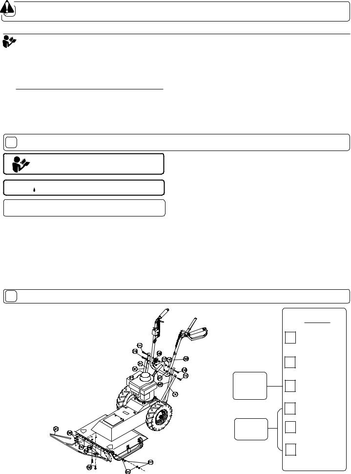
10 ASSEMBLY
Read all safety and operating instructions before assembling or starting this unit.
 PUT OIL IN ENGINE BEFORE STARTING.
DISCONNECT SPARK PLUG WIRE
BEFORE ASSEMBLING UNIT.
Your Billy Goat Brush Cutter is shipped from the factory in one carton, completely assembled except for the upper handle, and front guard bar.
1.REMOVE unit from carton and allow upper handle (item 40) to lay on ground behind unit. Set guard bar(Item 31) to the side for now.
2.REMOVE hardware items 115, 117, 141, 143, & 144 from temporary storage positions on lower handle (items 51, & 52).
3.ATTACH upper handle to lower as shown below, and securely tighten all fasteners. For easy alignment of handles during installation, loosen the four screws that secure the lower handles. Line up and hand tighten all handle hardware before final tightening. Note: Be sure the engine starter rope is properly installed in the starter rope guide (item 145) before tightening the corresponding fasteners.
4.REMOVE hardware items 102, 103, 117, 119, 124, 141, & 152 from temporary storage positions on deck and skid assy at front of unit (items 2, 155, & 156)
5.ATTACH guard bar(Item 31) to deck as shown below. Install the center bolts(Item 153) first, and install the bolts that fasten through the sides of the deck last. Securely tighten all fasteners. Note: Hardware items 117, 119, & 141 are used to secure both the front skid attachment and the sides of the guard bar. Be sure both are securely attached.
6.CONNECT spark plug wire to spark plug.
11 PACKING CHECKLIST
These items should be included in your carton. If any of these parts are missing, contact your dealer.
Literature
Assy
Engine
Manual
Per Model
Check
Handle Upper Assembly 500256
Check
Bar Support WA 500235
Check
Literature Assy 500263
Check
Briggs & Stratton
Check
Honda(English)
Check
Honda W/Electric
Start (English)
Part No. 500264 |
Page 3 of 12 |
Form No. F071300A |

12 |
LITERATURE ASSY P/N 500263 |
13 CONTROLS |
Throttle Control
Literature Checklist
Briggs and Honda engines have a choke type carburetor that is operated by moving the throttle control to the full start position. See STARTING section, see page 5.
Ty Wrap 900407
Qty: (4)
|
Check |
Owner's |
|
|
|
Owner's |
|
|
|
|
|
|
Manual |
|
|
|
|
Manual |
|
BRIGGS & |
HONDA |
||
|
500264 |
||||
|
|
|
|
|
|
|
|
|
STRATTON |
|
|
|
|
|
|
Pull Start |
Electric Start |
|
Check |
Warranty |
START |
PULL OUT |
PULL OUT |
|
|
|
|||
Warranty |
|
PULL OUT FOR CHOKE |
PULL OUT FOR CHOKE |
||
|
|
Card |
|
STARTING: |
STARTING: |
Card |
|
|
AND TURN TO LOCK |
AND TURN TO LOCK |
|
|
400972 |
|
AFTER STARTING: |
AFTER STARTING: |
|
|
|
|
|||
|
|
|
|
RELEASE FROM |
RELEASE FROM |
|
|
|
|
CHOKE AND ADJUST |
CHOKE AND ADJUST |
|
|
|
|
ENGINE TO DESIRED |
ENGINE TO DESIRED |
|
|
|
|
SPEED |
SPEED |
|
|
|
|
PUSH IN |
PUSH IN |
|
|
|
|
NOTE: WHEN ADJUSTING THROTTLE CONTROL TURN |
NOTE: WHEN ADJUSTING THROTTLE CONTROL TURN |
|
|
|
|
THROTTLE CONTROL HANDLE CLOCKWISE TO LOCK, |
THROTTLE CONTROL HANDLE CLOCKWISE TO LOCK, |
|
|
|
|
THEN TURN COUNTER CLOCKWISE 1/4 TURN TO |
THEN TURN COUNTER CLOCKWISE 1/4 TURN TO |
|
|
|
|
RELEASE BEFORE ADJUSTING SPEED. |
RELEASE BEFORE ADJUSTING SPEED. |
EU Declaration |
Check |
EU Declaration |
|
RUN |
START (PULL UP) |
|
of Conformity & |
|
|||
of Conformity |
|
|
|
|
|
|
EU Distributor |
|
|
RUN |
|
& EU |
|
|
|
||
|
|
|
|
|
|
Distributor List |
|
List 500265 |
|
OFF |
OFF |
|
|
|
|
||
|
|
|
STOP |
TM |
TM |
|
|
|
|
PART NO. 500309 |
PART NO. 500314 |
14 INSTRUCTION LABELS
These labels should be included on your Brush Cutter. If any of these labels are damaged, replace them before putting this equipment into operation. Item and part numbers are given to help in ordering replacement labels..
15 ENGINE LABELS
Briggs & Stratton
 WARNING
EXPLOSIVE FUEL |
400268 |
|
STOP ENGINE AND ALLOW T O
COOL BEFORE REFUELING.
Label Do Not Fill While
Engine Is Hot
Item 63 Part No.400268
 WARNING
890254 |
900327 |
Label Ear Eye Breathing Item
No. 188 Part No. 890254 Label Warning Guards Item 185 Part No.900327
Read Owner’s Manual Before Operating.
Lire le manuel d’utilisation avant la mise en route.
Vor Inbetriebnahme Bedienungs - und Wartungsanleitung lesen.
Favor leer las instrucciones de operacion' |
antes de operar el motor. |
|
|
' |
' |
Consultare il Manuale Uso e Manutenzione prima dell utilizzo. |
||
.. |
.. |
|
Las Skotselinstruktionen Innan Start. |
|
|
Label Danger Keep Hands and
Feet Away
Item 180 PartNo.400424
R
 N 1 2 3
Label Shift BC2400
Item No. 186
Part No. 500202
DANGER |
Honda |
|
|
810736 |
|
Label Danger Flying |
Label Read Owner's |
|
Material Item 184 |
||
Manual Item No. 187 |
||
Part No.810736 |
||
Part No. 890301 |
||
|
500177 |
500176 |
Label Clutch Blade |
Label Clutch Drive |
Item 192 |
Item 191 |
Part No.500177 |
Part No.500176 |
WHEELS MUST BE CHOCKED |
OR BLOCKED WHEN UNIT IS |
PARKED ON A SLOPE. |
500168 |
US DESIGN PATENT
NO: D386768
PART NO. 500279
Label Patent No
Item 190 Part No.500279
Label Chock Wheels Item No. 189 Part No. 500168
Part No. 500264 |
Page 4 of 12 |
Form No. F071300A |
 Loading...