


XR4400
PRO |
MULTIGATE® |
User’s Manual
Version 1.1 April 2001
www.behringer.com
ENGLISH
MULTIGATE PRO XR4400
SAFETY INSTRUCTIONS
CAUTION: To reduce the risk of electric shock, do not remove the cover (or back). No user serviceable parts inside; refer servicing to qualified personnel.
WARNING: To reduce the risk of fire or electric shock, do not expose this appliance to rain or moisture.
This symbol, wherever it appears, alerts you to the presence of uninsulated dangerous voltage inside the enclosure—voltage that may be sufficient to constitute a risk of shock.
This symbol, wherever it appears, alerts you to important operating and maintenance instructions in the accompanying literature. Read the manual.
DETAILED SAFETY INSTRUCTIONS:
All the safety and operation instructions should be read before the appliance is operated.
Retain Instructions:
The safety and operating instructions should be retained for future reference.
Heed Warnings:
All warnings on the appliance and in the operating instructions should be adhered to.
Follow instructions:
All operation and user instructions should be followed.
Water and Moisture:
The appliance should not be used near water (e.g. near a bathtub, washbowl, kitchen sink, laundry tub, in a wet basement, or near a swimming pool etc.).
Ventilation:
The appliance should be situated so that its location or position does not interfere with its proper ventilation. For example, the appliance should not be situated on a bed, sofa, rug, or similar surface that may block the ventilation openings, or placed in a built-in installation, such as a bookcase or cabinet that may impede the flow of air through the ventilation openings.
Heat:
The appliance should be situated away from heat sources such as radiators, heat registers, stoves, or other appliances (including amplifiers) that produce heat.
Power Source:
The appliance should be connected to a power supply only of the type described in the operating instructions or as marked on the appliance.
Grounding or Polarization:
Precautions should be taken so that the grounding or polarization means of an appliance is not defeated.
Power-Cord Protection:
Power supply cords should be routed so that they are not likely to be walked on or pinched by items placed upon or against them, paying particular attention to cords and plugs, convenience receptacles and the point where they exit from the appliance.
Cleaning:
The appliance should be cleaned only as recommended by the manufacturer.
Non-use Periods:
The power cord of the appliance should be unplugged from the outlet when left unused for a long period of time.
Debris and Liquid Entry:
Care should be taken that debris and/or liquids do not enter the enclosure through openings.
Damage Requiring Service:
The appliance should be serviced by qualified service personnel when:
-The power supply cord or the plug has been damaged; or
-Debris or liquid has entered the appliance; or
-The appliance has been exposed to rain; or
-The appliance does not appear to operate normally or exhibits a marked change in performance; or
-The appliance has been dropped, or the enclosure damaged.
Servicing:
The user should not attempt to service the appliance beyond that which is described in the operating instructions. All other servicing should be referred to qualified service personnel.
2

MULTIGATE PRO XR4400
FOREWORD
Dear Customer,
Welcome to the team of MULTIGATE PRO users and thank you very much for expressing your confidence in BEHRINGER products by purchasing this unit.
It is one of my most pleasant tasks to write this letter to you, because it is the culmination of many months of hard work delivered by our engineering team to reach a very ambitious goal: making an outstanding device better still. The MULTIGATE has for quite a long time been a standard tool used by numerous studios and PA rental companies. The task to improve one of our best-selling products certainly meant a great deal of responsibility, which we assumed by focusing on you, the discerning user and musician. It also meant a lot of work and night shifts to accomplish this goal. But it was fun, too. Developing a product usually brings a lot of people together, and what a great feeling it is when everybody who participated in such a project can be proud of what we’ve achieved.
It is our philosophy to share our joy with you, because you are the most important member of the BEHRINGER family. With your highly competent suggestions for new products you’ve greatly contributed to shaping our company and making it successful. In return, we guarantee you uncompromising quality (manufactured under ISO9000 certified management system) as well as excellent technical and audio properties at an extremely favorable price. All of this will enable you to fully unfold your creativity without being hampered by budget constraints.
We are often asked how we can make it to produce such high-grade devices at such unbelievably low prices. The answer is quite simple: it’s you, our customers! Many satisfied customers means large sales volumes enabling us to get better conditions of purchase for components, etc. Isn’t it only fair to pass this benefit back to you? Because we know that your success is our success, too!
I would like to thank all people whose help on “Project MULTIGATE PRO” has made it all possible. Everybody has made very personal contributions, starting from the designers of the unit via the many staff members in our company to you, the user of BEHRINGER products.
My friends, it’s been worth the trouble!
Thank you very much,
Uli Behringer
3
MULTIGATE PRO XR4400
MULTIGATE® PRO
Audio interactive 4-channel expander/gate of the high-end class
sHigh-precision parametric filter for frequency selective operation
sUTR (Ultra Transient Response) selectable ultra-fast gate XR4400
sIRC (Interactive Ratio Control) selectable ultra-smooth expander
sFully adjustable ratio control in expander mode
sFully adjustable attenuation control in gate mode
sIndependent hold/release controls for any envelope shaping
sFlexLink system for flexible master/slave configurations
sFilter monitor facility for monitoring the filter section
sHigh-performance VCAs on all channels
sUltra-low noise 4580 audio operational amplifiers for outstanding sound performance
sPrecise 8-segment metering for gain reduction
sAccurate “traffic light” display for easy threshold setting
sTrue RMS level detection for “inaudible” performance
sServo-balanced gold-plated XLR and 1/4" TRS inputs and outputs
sHigh-quality detented potentiometers and illuminated switches
sManufactured under ISO9000 certified management system
4

MULTIGATE PRO XR4400
TABLE OF CONTENT
1. INTRODUCTION..................................................................................................................... |
6 |
|
1.1 Technical background...................................................................................................................... |
7 |
|
1.1.1 Noise as a physical phenomenon ......................................................................................... |
7 |
|
1.1.2 What are audio dynamics? ................................................................................................... |
7 |
|
1.1.3 |
Compressors/limiters ............................................................................................................ |
8 |
1.1.4 |
Expanders/noise gates ......................................................................................................... |
9 |
2. THE DESIGN CONCEPT ....................................................................................................... |
9 |
|
2.1 |
High quality components and design ............................................................................................... |
9 |
2.2 |
Inputs and outputs ........................................................................................................................ |
10 |
|
2.2.1 Balanced inputs and outputs ............................................................................................... |
10 |
3. INSTALLATION ..................................................................................................................... |
10 |
|
3.1 |
Rack mounting .............................................................................................................................. |
10 |
3.2 |
Mains voltage ................................................................................................................................ |
10 |
3.3 |
Audio connections ........................................................................................................................ |
10 |
4. CONTROLS .......................................................................................................................... |
12 |
||
4.1 |
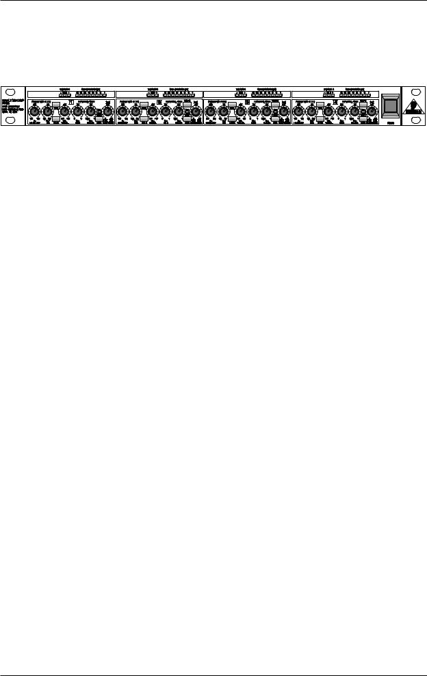
The front panel control elements ................................................................................................... |
12 |
|
4.2 |
The rear panel elements ................................................................................................................ |
13 |
|
5. TECHNICAL BACKGROUND .............................................................................................. |
14 |
||
5.1 |
EXPANDER mode ......................................................................................................................... |
14 |
|
5.2 |
Interactive control functions ........................................................................................................... |
14 |
|
|
5.2.1 |
THRESHOLD control .......................................................................................................... |
14 |
|
5.2.2 Attack, release and hold times ........................................................................................... |
15 |
|
|
5.2.3 IAC circuit (Interactive Attack Control) ................................................................................. |
15 |
|
|
5.2.4 |
RANGE function ................................................................................................................. |
15 |
|
5.2.5 IRC circuit (Interactive Ratio Control) ................................................................................... |
16 |
|
|
5.2.6 |
RATIO function .................................................................................................................... |
16 |
5.3 |
FLEXLINK function ........................................................................................................................ |
16 |
|
5.4 |
The SIDECHAIN filter .................................................................................................................... |
17 |
|
|
5.4.1 |
The MONITOR function ....................................................................................................... |
17 |
6. APPLICATIONS ..................................................................................................................... |
17 |
||
6.1 |
Basic setting ................................................................................................................................. |
17 |
|
|
6.1.1 |
The gate function ................................................................................................................ |
17 |
|
6.1.2 |
The expander function ......................................................................................................... |
19 |
6.2 |
Proper positioning of microphones ................................................................................................ |
19 |
|
6.3 |
Applications .................................................................................................................................. |
19 |
|
|
6.3.1 Suppressing crosstalk in multi-track applications ................................................................ |
19 |
|
|
6.3.2 Reducing crosstalk in stage microphones ........................................................................... |
20 |
|
|
6.3.3 Reducing feedback in stage microphones ........................................................................... |
20 |
|
7. SPECIFICATIONS .................................................................................................................. |
21 |
||
8. WARRANTY ........................................................................................................................... |
22 |
||
5

MULTIGATE PRO XR4400
1. INTRODUCTION
With the BEHRINGER MULTIGATE PRO you purchased a dynamics processor of the high-end class designed to meet highest requirements: professional recording, broadcast and television studios, CD and digital production facilities, etc. Its complete range of features and innovative circuit topology make the MULTIGATE PRO an all-purpose device for reducing noise in audio recordings, for automatically muting stage mics, expanding the dynamic range of compressed recordings, improving the signal-to-noise ratio of noisy communications systems and for producing special effects, etc.
Future-oriented BEHRINGER technology
Our MULTIGATE range of devices has been a hit ever since we introduced our first model several years ago. This expander/gate is based on many years of experience and findings in psychoacoustics and is used throughout the world in renowned studios, sound reinforcement systems as well as in broadcast and television studios.
It was a real challenge to improve the well-known MULTIGATE even further, and we are proud of our success. Compared to its predecessor models, the MULTIGATE PRO not only has additional features, but also comes with dramatically improved functionalities. For example, it now has a parametric filter enabling you to accurately set the trigger frequencies, while the FlexLink system allows for great flexibility when linking the device’s individual channels in a master/slave configuration.
Basically, quadruple gates are not a new invention. However, packing four simple noise gates into one enclosures usually means a compromise in terms of ease of operation and functionality. Too many control elements make such a device impossible to handle, and if you sacrifice crucial functions for the sake of easy operation, the range of useful applications is restricted considerably.
The BEHRINGER MULTIGATE PRO is a quadruple expander/gate with a maximum of functionalities and can still be operated conveniently. Interactive functions make it easy and efficient to specifically process any kind of program material, while the need for “adjustment work” has been reduced drastically. Each of the MULTIGATE PRO’s four sections comprises an ultra-fast gate, a program-dependent expander, a filter section and high-precision meters indicating both threshold point and gain reduction.
The IAC circuit (Interactive Attack Control)
One of the MULTIGATE PRO’s most outstanding features is the program-dependent control of attack times. The new IAC circuit (Interactive Attack Control) analyzes the program material to calculate the attack time by way of interaction, so that the hold/release process is triggered automatically depending on the program, which is why the MULTIGATE PRO does not need a dedicated attack control.
Switchable gate/expander function
Another highlight of the MULTIGATE PRO is the switchable operating mode of gate and expander. With the MODE function off, the MULTIGATE PRO works in gate mode using an extremely fast attack time to gate all kinds of drum and synthesizer sounds, without cutting their percussive edge.
In expander mode the device analyzes the shape and dynamic contents of the input signal to calculate the control time parameters. It thus works as an interactive expander that adapts automatically to the program signal. The result: guitar sounds, vocals and complex mix signals can be “cleaned” without audible clicks, breathing or other detrimental effects. Additionally, you can freely expand any type of program material in its dynamic range.
Side-chain filter section
When several microphones are used, for example to pick up a drum set, crosstalk between microphones can lead to unwanted triggering of the gate. The built-in parametric sidechain filter of the MULTIGATE PRO allows the user to accurately select the frequencies causing the trouble, so that the device responds to these frequencies only. The monitor function can be used to pre-monitor the filter, making it easier to adapt the circuitry to the acoustic properties of the program material.
FlexLink system
An innovative couple function gives you great flexibility to synchronize the expander/gate sections in a master/ slave configuration.
6 |
1. INTRODUCTION |

MULTIGATE PRO XR4400
+The following operational manual will introduce you to the BEHRINGER MULTIGATE PRO and its various functions. After reading the manual carefully, make sure it is always on hand for future reference.
1.1 Technical background
By employing current modern analog technology it is possible to manufacture audio equipment with a dynamic range of up to 130 dB. In contrast to analog techniques, the dynamic range of digital equipment is approximately 25 dB less. With conventional record and tape recorder technology, as well as broadcasting, this value is further reduced. Generally, dynamic restrictions are due to noisy storage in transmission media and also the maximum headroom of these systems.
1.1.1 Noise as a physical phenomenon
All electrical components produce a certain level of inherent noise. Current flowing through a conductor leads to uncontrolled random electron movements. For statistical reasons, this produces frequencies within the whole audio spectrum. If these currents are highly amplified, the result will be perceived as noise. Since all frequencies are equally affected, we term this white noise. It is fairly obvious that electronics cannot function without components. Even if special low-noise components are used, a certain degree of basic noise cannot be avoided.
This effect is similar when replaying a tape. The non-directional magnetic particles passing the replay head can also cause uncontrolled currents and voltages. The resulting sound of the various frequencies is heard as noise. Even the best possible tape biasing can “only” provide signal-to-noise ratios of about 70 dB, which is not acceptable today since the demands of listeners have increased. Due to the laws of physics, improving the design of the magnetic carrier is impossible using conventional means.
1.1.2 What are audio dynamics?
A remarkable feature of the human ear is that it can detect the most wide ranging amplitude changes—from the slightest whisper to the deafening roar of a jet-plane. If one tried to record or reproduce this wide spectrum of sound with the help of amplifiers, cassette recorders, records or even digital recorders (CD, DAT etc.), one would immediately be restricted by the physical limitations of electronic and acoustic sound reproduction technology.
The usable dynamic range of electro-acoustic equipment is limited as much at the low end as at the high end. The thermal noise of the electrons in the components results in an audible basic noise floor and thus represents the bottom limit of the transmission range. The upper limit is determined by the levels of the internal operating voltages; if they are exceeded, audible signal distortion is the result. Although in theory, the usable dynamic range sits between these two limits, it is considerably smaller in practice, since a certain reserve must be maintained to avoid distortion of the audio signal if sudden level peaks occur. Technically speaking, we refer to this reserve as “headroom”—usually this is about 10 - 20 dB. A reduction of the operating level would allow for greater headroom, i.e. the risk of signal distortion due to level peaks would be reduced. However, at the same time, the basic noise floor of the program material would be increased considerably.
1. INTRODUCTION |
7 |
 Loading...