


User Manual
CLIP |
SIG |
CLIP |
SIG |
ENGLISH
XENYX 1002FX/1202FX
Premium 10/12-Input 2-Bus Mixer with XENYX Mic Preamps, British EQs and 24-Bit Multi-FX Processor
Thank you
Congratulations! In purchasing our XENYX 1002FX/1202FX you have acquired a mixing console whose small size belies its incredible versatility and audio performance.
This manual is available in English, German, French, Spanish, Italian, Russian, Polish, Dutch, Finnish, Swedish, Danish, Portuguese, Greek, Japanese
and Chinese. There may also be more current versions of this document. Download them by going to the appropriate product page at:
www.behringer.com
Table of Contents
Thank you...................................................................... |
1 |
|||||||||||||||
Important Safety Instructions.................................... |
2 |
|||||||||||||||
1. |
Introduction............................................................. |
3 |
||||||||||||||
|
1.1 |
General mixing console functions........................................ |
3 |
|||||||||||||
|
1.2 The user’s manual.......................................................................... |
4 |
||||||||||||||
|
1.3 |
Before you get started................................................................ |
4 |
|||||||||||||
2. |
Control elements and connectors......................... |
5 |
||||||||||||||
|
2.1 |
Mono Channels.............................................................................. |
5 |
|||||||||||||
|
2.2 |
Stereo channels.............................................................................. |
6 |
|||||||||||||
|
2.3 |
Connector array of the main section.................................... |
7 |
|||||||||||||
|
2.4 |
Main section.................................................................................... |
8 |
|||||||||||||
|
2.5 |
Digital effects processor............................................................. |
9 |
|||||||||||||
3. |
Applications........................................................... |
10 |
||||||||||||||
|
3.1 |
Recording studio........................................................................ |
10 |
|||||||||||||
|
3.2 |
Live sound..................................................................................... |
12 |
|||||||||||||
4. |
Installation............................................................. |
13 |
||||||||||||||
|
4.1 |
Mains Connection...................................................................... |
13 |
|||||||||||||
|
4.2 |
Audio connections.................................................................... |
13 |
|||||||||||||
5. |
Specifications......................................................... |
14 |
||||||||||||||
Limited warranty........................................................ |
16 |
|||||||||||||||
Legal Disclaimer......................................................... |
17 |
|||||||||||||||
|
|
|
|
|
|
|
|
|
|
|
|
|
|
|
|
|
|
|
|
|
|
|
|
|
|
|
|
|
|
|
|
|
|
|
|
|
|
|
|
|
|
|
|
|
|
|
|
|
|
|
|
|
|
|
|
|
|
|
|
|
|
|
|
|
|
|
|
|
|
|
|
|
|
|
|
|
|
|
|
|
|
|
|
|
A50-00000-03477

ENGLISH
2 |
XENYX 1002FX/1202FX User Manual |
|
Important Safety Instructions
*
Terminals marked with this symbol carry electrical current of sufficient magnitude to constitute risk of electric shock. Use only high-quality commercially-available speaker cables with ¼" TS plugs pre-installed. All other installation or modification should be performed only by qualified personnel.
*
This symbol, wherever it appears, alerts you to the presence of uninsulated dangerous voltage inside the enclosure - voltage that may be sufficient to constitute a risk of shock.
!
This symbol, wherever it appears, alerts you to important operating and maintenance instructions in the accompanying literature. Please read the manual.
!Caution
To reduce the risk of electric shock, do not remove the top cover (or the rear section). No user serviceable parts inside. Refer servicing to qualified personnel.
!Caution
To reduce the risk of fire or electric shock, do not expose this appliance to rain and moisture. The apparatus shall not be exposed to dripping or splashing liquids and no objects filled with liquids, such as vases, shall be placed on the apparatus.
!Caution
These service instructions are for use by qualified service personnel only. To reduce the risk of electric shock do not perform any servicing other than that contained in the operation instructions. Repairs have to be performed by qualified service personnel.
[1] Read these instructions.
[2] Keep these instructions.
[3] Heed all warnings.
[4] Follow all instructions.
[5] Do not use this apparatus near water.
[6] Clean only with dry cloth.
[7] Do not block any ventilation openings. Install in accordance with the manufacturer’s instructions.
[8] Do not install near any heat sources such as radiators, heat registers, stoves, or other apparatus (including amplifiers) that produce heat.
[9] Do not defeat the safety purpose of the polarized or groundingtype plug. A polarized plug has two blades with one wider than the other. A grounding-type plug has two blades and
a third grounding prong. The wide blade or the third prong are provided for your safety. If the provided plug does not fit into your outlet, consult an electrician for replacement of the obsolete outlet.
{10} Protect the power cord from being walked on or pinched particularly at plugs, convenience receptacles, and the point where they exit from the apparatus.
{11} Use only attachments/accessories specified by the manufacturer.
{12} Use only with the cart, stand, tripod, bracket, or table specified by the manufacturer, or sold with the apparatus. When a cart is used, use caution when moving the cart/apparatus combination to avoid injury from tip-over.
{13} Unplug this apparatus during lightning
storms or when unused for long periods of time.
{14} Refer all servicing to qualified service personnel. Servicing is required when the apparatus has been damaged in any way, such as power supply cord or plug is damaged, liquid has been spilled or objects have fallen into the apparatus, the apparatus has been exposed to rain or moisture, does not operate normally, or has been dropped.
{15} The apparatus shall be connected to a MAINS socket outlet with a protective earthing connection.
{16} Where the MAINS plug or an appliance coupler is used as the disconnect device, the disconnect device shall remain readily operable.

XENYX 1002FX/1202FX User Manual
1. Introduction
The BEHRINGER XENYX mixing console offers you premiumquality microphone preamplifiers with optional phantom power supply, balanced line inputs and the ability to connect external effects processors. Because of its extensive and carefully thought-out routing possibilities, your XENYX lends itself equally to both live and studio use.
The XENYX Series represents a milestone in the development of mixing console technology. With the new XENYX microphone preamps including phantom power as an option, balanced line inputs and a powerful effects section, the mixing consoles in the XENYX Series are optimally equipped for live and studio applications. Owing to state-of-the-art circuitry your XENYX console produces a warm analog sound that is unrivalled. With the addition of the latest digital technology these best-in-class
consoles combine the advantages of both analog and digital technology.
The microphone channels feature high-end XENYX Mic Preamps that compare well with costly outboard preamps in terms of sound quality and dynamics and boast the following features:
• 130 dB dynamic range for an incredible amount of headroom
• A bandwidth ranging from below 10 Hz to over 200 kHz for crystal-clear reproduction of even the finest nuances
• The extremely low-noise and distortion-free circuitry guarantees absolutely natural and transparent signal reproduction
• They are perfectly matched to every conceivable microphone with up to 60 dB gain and +48 volt phantom power supply
• They enable you to use the greatly extended dynamic range of your 24-bit/192-kHz HD recorder to the full, thereby maintaining optimal audio quality
“British EQ”
The equalizers used for the XENYX Series are based on the legendary circuitry of top-notch consoles made in
Britain, which are renowned throughout the world for their incredibly warm and musical sound character. Even with extreme gain settings these equalizers ensure outstanding audio properties.
3
Multi-effects processor
Additionally, your XENYX mixing console has an effects processor with 24-bit A/D and D/A converters included, which gives you 100 presets producing first-class reverb, delay and modulation effects plus numerous multi-effects in excellent audio quality.
CAUTION!
◊We should like to draw your attention to the fact that extreme volumes may damage your hearing and/ or your headphones or loudspeakers. Turn the MAIN MIX control and PHONES control in the main section fully counterclockwise before you switch on the unit. Always be careful to set appropriate volume levels.
1.1 General mixing console functions
A mixing console fulfils three main functions:
• Signal processing: Preamplification
Microphones convert sound waves into voltage that has to be amplified several-fold; then, this voltage is turned into sound that is reproduced in a loudspeaker. Because microphone capsules are very delicate in their construction, output voltage is very low and therefore susceptible to interference. Therefore, mic signal voltage is amplified directly at the mixer input to a higher signal level that is less prone to interference. This higher, interference-safe signal level has to be achieved through amplification using an amplifier of the highest quality in order to amplify the signal and add as little noise to
it as possible. The XENYX Mic Preamp performs this role beautifully, leaving no traces of noise or sound coloration. Interference that could take place at the preamplification level could affect signal quality and
purity, and would then be passed on to all other devices, resulting in inaccurate sounding program during recording or playback.
Level-setting
Signals fed into the mixer using a DI-box
(Direct Injection) or the output of a sound card or a keyboard, often have to be adjusted to the operating level of your mixing console.
ENGLISH

ENGLISH
4
Frequency response correction
Using the equalizers found in each channel strip, you can simply, quickly and effectively adjust the way a signal sounds.
• Signal distribution:
Individual, processed signals from the channel strips are compiled on busses and are fed into the main section for further processing. Connections for recording equipment, power amplifiers, headphones as well as CD/tape connectors are available here. The mix is sent to the internal FX processors or external effects processors via aux sends and returns. Similarly, a mix can be created for the musicians on the stage (monitor mix).
• Mix:
Mix:
All other mixing console functions fall under this vital category. Creating a mix means primarily adjusting the volume levels of individual instruments and voices to one another as well as giving them the appropriate weight within the overall frequency spectrum. Likewise, you’ll have to sensibly spread individual voices across the stereo image of a signal. At the end of this process, adjusting the level of the entire mix to other equipment in the signal path is required (e. g. recorder/crossover/ amplifier).
The interface of BEHRINGER mixing consoles is optimized for these tasks, enabling you to easily keep track of the signal path.
1.2 The user’s manual
The user’s manual is designed to give you both an overview of the controls, as well as detailed information on how to use them. In order to help you understand the links between the controls, we have arranged them in groups according to their function. If you need to know more about specific issues, please visit our website at http://www.behringer.com. Additional information
and explanations about various music industry/audio technology terminology can be found on individual product pages as well as in the glossary area of www.behringer.com.
◊The block diagram supplied with the mixing console gives you an overview of the connections between the inputs and outputs, as well as the associated switches and controls.
For the moment, just try and trace the signal path from the microphone input to the FX SEND connector. Don’t be put off by the huge range of possibilities; it’s easier than you think! If you look at the overview of the controls at the same time, you’ll be able to quickly familiarize yourself with your mixing console and you’ll soon be making the most of all its many possibilities.
XENYX 1002FX/1202FX User Manual
1.3 Before you get started
1.3.1 Shipment
Your mixing console was carefully packed in the factory to guarantee safe transport. Nevertheless, we recommend that you carefully examine the packaging and its contents for any signs of physical damage that may have occurred during transit.
◊If the unit is damaged, please do NOT return it to us, but notify your dealer and the shipping company immediately, otherwise claims for damage or replacement may not be granted.
◊To assure optimal protection of your XENYX during use or transport, we recommend utilizing a carrying case.
◊Please always use the original packaging to avoid damage due to storage or shipping.
◊Never let unsupervised children play with the XENYX or with its packaging.
◊Please dispose of all packaging materials in an environmentally-friendly fashion.
1.3.2 Initial operation
◊Be sure that there is enough space around the unit for cooling purposes and to avoid overheating please do not place your mixing console on high-temperature equipment such as radiators or power amps.
◊Never connect the XENYX to the power supply unit when the latter is connected to the mains! First connect the power supply unit to the console, then connect the power supply unit to the mains.
◊Please make sure that all units have a proper ground connection. For your own safety, never remove or disable the ground conductor from the unit or on the AC power cord. The unit should always be connected to a mains socket outlet with a protective earthing connection.
◊When installing the product, ensure the appliance coupler or power cord is easily accessible for disconnecting the unit from mains.
1.3.3 Online registration
Please, do remember to register your new
BEHRINGER equipment right after your purchase by visiting www.behringer.com (alternatively www.behringer.de)
and kindly read the terms and conditions of our warranty carefully.
Should your BEHRINGER product malfunction, our goal is to have it repaired as quickly as possible. To arrange for
warranty service, please contact the retailer from whom the equipment was purchased. Should your BEHRINGER dealer
XENYX 1002FX/1202FX User Manual
not be located in your vicinity, you may directly contact one of our subsidiaries. Corresponding contact information is included in the original equipment packaging (Global
Contact Information/European Contact Information). Should your country not be listed, please contact the distributor nearest you. A list of distributors can be found in the support area of our website (www.behringer.com).
Registering your purchase and equipment with us helps us process your repair claims quicker and more efficiently.
Thank you for your cooperation!
2. Control elements and connectors
This chapter describes the various control elements of your mixing console. All controls, switches and connectors will be discussed in detail.
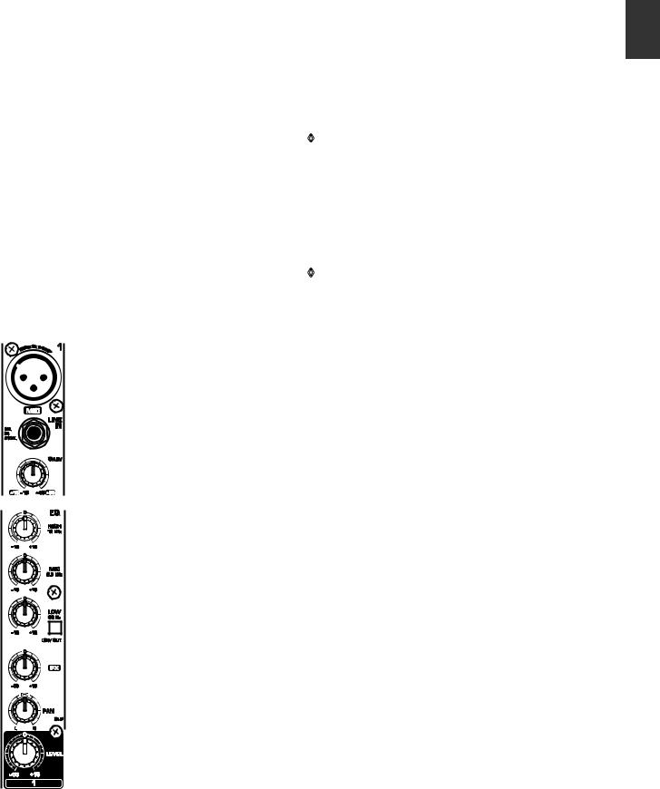
2.1 Mono Channels
5
MIC
Each mono input channel offers a balanced microphone input via the XLR connector and also features switchable +48 V phantom power supply for condenser microphones. The XENYX preamps provide undistorted and noise-free gain as is typically known only from costly outboard preamps.
◊Please mute your playback system before you activate the phantom power supply to prevent switch-on thumps being directed to your loudspeakers. Please also note the instructions in chapter 2.4“Main section”.
LINE IN
Each mono input also features a balanced line input on a ¼" connector. Unbalanced devices (mono connectors) can also be connected to these inputs.
◊Please remember that you can only use either the microphone or the line input of a channel at any one time. You can never use both simultaneously!
GAIN
Use the GAIN control to adjust the input gain. This control should always be turned fully counterclockwise whenever you connect or disconnect a signal source to one of the inputs.
The scale has 2 different value ranges: the first value range (+10 to +60 dB) refers to the MIC input and shows the amplification for the signals fed in there.
The second value range (+10 to -40 dBu) refers to the line input and shows its sensitivity. The settings for equipment with standard line-level signals (-10 dBV or +4 dBu) look like this: While the GAIN control is turned all the way down, connect your equipment. Set the GAIN control to the external devices’standard output level. If that unit has an output signal level display, it should show 0 dB during signal peaks. For +4 dBu, turn up GAIN slightly, for -10 dBV a bit more. Tweaking is done using the CLIP LED.
EQ
All mono input channels include a 3-band equalizer. All bands provide boost or cut of up to 15 dB. In the central position, the equalizer is inactive.
The circuitry of the British EQs is based on the technology used in the best-known top-of-the-line consoles and providing a warm sound without any unwanted side effects. The result are extremely musical equalizers which, unlike simple equalizers, cause no side effects such as phase shifting or bandwidth limitation, even with extreme gain settings of ±15 dB.
ENGLISH
Fig. 2.1: Connectors and controls on the mono channels
ENGLISH
6
The upper (HIGH) and the lower band (LOW) are shelving filters that increase or decrease all frequencies above or below their cut-off frequency. The cut-off frequencies of the upper and lower band are 12 kHz and 80 Hz respectively. The mid band is configured as a peak filter with a center frequency of 2.5 kHz. Unlike shelving filters, the peak filter processes a frequency range that extends upwards and downwards around its middle frequency.
LOW CUT
In addition, the mono channels are equipped with a steep LOW CUT filter (slope at 18 dB/oct., -3 dB at 75 Hz) designed to eliminate unwanted low-frequency signal components. These can be noises created by hand-held microphones, subsonic noise or plosive sounds created by highly sensitive microphones.
FX
FX sends enable you to feed signals via a variable control from one or more channels and sum these signals to a bus. The bus appears at the console’s FX send output and can be fed from there to an external effects device. The return from the effects unit is then brought back into the console on the stereo channels. Each FX send is mono and features up to +15 dB gain.
As the name suggests, the FX sends of the XENYX mixing consoles are intended to drive effects devices (reverb, delay, etc.) and are therefore configured post-fader. This means that the mix between dry signal and effect remains at the level determined by the channel’s aux send, irrespective of the channel fader setting. If this were not the case, the effects signal of the channel would remain audible even when the fader is lowered to zero. With XENYX mixing consoles, the channel fader is called LEVEL control.
In the 1002FX/1202FX, the FX send is routed directly to the built-in effects processor. To make sure that the effects processor receives an input signal, you shouldn’t turn this control all the way to the left (-oo).
PAN
The PAN control determines the position of the channel signal within the stereo image. This control features a constant-power characteristic, which means the signal is always maintained at a constant level, irrespective of position in the stereo panorama.
XENYX 1002FX/1202FX User Manual
LEVEL
The LEVEL control determines the level of the channel signal in the main mix.
◊Attention: Since the FX path for the effect processor is connected post-fader, the LEVEL control has to be turned up in order to get this channel’s signal to the effects processor!
CLIP
The CLIP-LED’s of the mono channels illuminate when the input signal is driven too high, which could cause distortion. If this happens, use the GAIN control to reduce the preamp level until the LED does not light anymore.
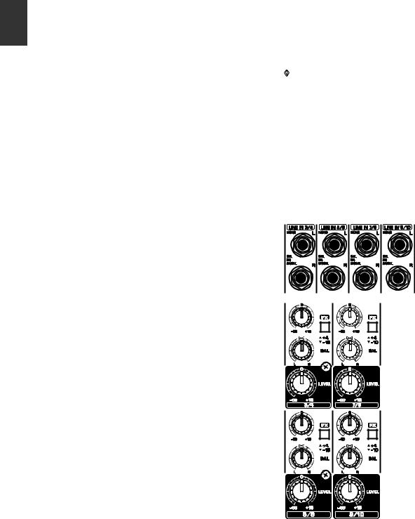
2.2 Stereo channels
Fig. 2.2: Connectors and controls on the stereo channels
 Loading...