


Models ESP904, ESP904E
Quad-Port Multi-Interface
Ethernet Serial Server
(RS-232/422/485)
Manual Documentation Number: ESP904-0504
B&B Electronics Mfg Co Inc – 707 Dayton Rd - PO Box 1040 - Ottawa IL 61350 - Ph 815-433-5100 - Fax 815-433-5104 – www.bb-elec.com B&B Electronics Ltd – Westlink Commercial Park – Oranmore, Galway, Ireland – Ph +353 91-792444 – Fax +353 91-792445 – www.bb-europe.com
International Headquarters
B&B Electronics Mfg. Co. Inc.
707 Dayton Road
P.O. Box 1040
Ottawa, IL 61350 USA
Phone (815) 433-5100 -- General Fax (815) 433-5105
Website: www.bb-elec.com
Sales e-mail: orders@bb-elec.com -- Fax (815) 433-5109
Technical Support e-mail: support@bb.elec.com -- Fax (815) 433-5104
European Headquarters
B&B Electronics Ltd.
Westlink Commercial Park
Oranmore, Co. Galway, Ireland
Phone +353 91-792444 -- Fax +353 91-792445
Website: www.bb-europe.com
Sales e-mail: sales@bb-europe.com
Technical Support e-mail: support@bb-europe.com
© B&B Electronics – February 2004
Manual Documentation Number: ESP904-0504
B&B Electronics Mfg Co Inc – 707 Dayton Rd - PO Box 1040 - Ottawa IL 61350 - Ph 815-433-5100 - Fax 815-433-5104 – www.bb-elec.com B&B Electronics Ltd – Westlink Commercial Park – Oranmore, Galway, Ireland – Ph +353 91-792444 – Fax +353 91-792445 – www.bb-europe.com

Table of Contents |
|
|
TABLE OF FIGURES................................................................................................. |
|
I |
CHAPTER 1: INTRODUCTION.............................................................................. |
|
1 |
FEATURES.................................................................................................................. |
|
1 |
COMMUNICATION MODES ......................................................................................... |
|
2 |
Direct IP Mode ..................................................................................................... |
|
2 |
Virtual COM Mode ............................................................................................... |
|
2 |
Paired Mode ......................................................................................................... |
|
3 |
Heart Beat............................................................................................................. |
|
3 |
ESP904 QUICK START GUIDE.................................................................................... |
|
4 |
Hardware Setup .................................................................................................... |
|
4 |
Software Installation............................................................................................. |
|
4 |
ESP904 Configuration .......................................................................................... |
|
5 |
Install Virtual COM Ports on PC.......................................................................... |
|
7 |
Check Communications ........................................................................................ |
|
7 |
ESP904 TECHNICAL DATA ........................................................................................ |
|
8 |
CHAPTER 2: MAKING THE HARDWARE CONNECTIONS ......................... |
11 |
|
PACKAGE CHECKLIST .............................................................................................. |
|
11 |
ESP904 CONNECTIONS, INDICATORS AND RESET SWITCH ...................................... |
12 |
|
Indicator Lights................................................................................................... |
|
12 |
Ethernet Connector............................................................................................. |
|
12 |
Power Connector ................................................................................................ |
|
13 |
Reset Button ........................................................................................................ |
|
13 |
Serial Ports ......................................................................................................... |
|
13 |
SERIAL PORT OPERATIONAL MODES ....................................................................... |
|
14 |
Default Mode ...................................................................................................... |
|
14 |
Console Mode ..................................................................................................... |
|
14 |
Upgrade Mode .................................................................................................... |
|
14 |
RS-232 Mode....................................................................................................... |
|
15 |
RS-422 Mode....................................................................................................... |
|
15 |
RS-485 Mode....................................................................................................... |
|
15 |
ESP904 SERIAL PORT CONNECTOR PIN-OUTS ......................................................... |
|
17 |
CHAPTER 3: INSTALLING THE VLINX ESP SOFTWARE ........................... |
19 |
|
SOFTWARE INSTALLATION....................................................................................... |
|
19 |
Manual Documentation Number: ESP904-0504 |
Table of Contents |
i |
B&B Electronics Mfg Co Inc – 707 Dayton Rd - PO Box 1040 - Ottawa IL 61350 - Ph 815-433-5100 - Fax 815-433-5104 – www.bb-elec.com B&B Electronics Ltd – Westlink Commercial Park – Oranmore, Galway, Ireland – Ph +353 91-792444 – Fax +353 91-792445 – www.bb-europe.com
|
Automatic Installation......................................................................................... |
|
19 |
|
Manual Installation............................................................................................. |
|
19 |
CHAPTER 4: USING ESP MANAGER................................................................. |
|
23 |
|
|
HARDWARE SETUP: ................................................................................................. |
|
23 |
|
SOFTWARE SETUP:................................................................................................... |
|
24 |
|
Server Icons Section............................................................................................ |
|
26 |
|
Serial Server List................................................................................................. |
|
26 |
|
Virtual COM List ................................................................................................ |
|
27 |
|
SEARCHING SERVER ................................................................................................ |
|
28 |
|
Server Properties Screen .................................................................................... |
|
28 |
CHAPTER 5: CONFIGURING THE ESP904 SERVER PROPERTIES ........... |
31 |
||
|
DESCRIPTION OF THE SERVER PROPERTIES .............................................................. |
|
31 |
|
Server Name........................................................................................................ |
|
31 |
|
Password............................................................................................................. |
|
31 |
|
DHCP ................................................................................................................. |
|
31 |
|
IP Address........................................................................................................... |
|
32 |
|
Netmask............................................................................................................... |
|
32 |
|
Gateway .............................................................................................................. |
|
32 |
|
MAC Address ...................................................................................................... |
|
32 |
|
Link Status........................................................................................................... |
|
32 |
|
Server Serial Port (Select 1 to 4) ........................................................................ |
|
33 |
|
Baud Rate............................................................................................................ |
|
33 |
|
Data/Parity/Stop ................................................................................................. |
|
33 |
|
Flow Control....................................................................................................... |
|
33 |
|
Connection Mode................................................................................................ |
|
33 |
|
TCP/UDP Protocol............................................................................................. |
|
34 |
|
TCP/UDP Port.................................................................................................... |
|
34 |
|
Remote IP Address.............................................................................................. |
|
34 |
|
Timeout ............................................................................................................... |
|
34 |
|
Update/Save ........................................................................................................ |
|
35 |
CHAPTER 6: INSTALLING VIRTUAL COM PORTS ...................................... |
37 |
||
|
VIRTUAL COM PORT INSTALLATION ...................................................................... |
|
37 |
|
MATCHING THE ESP904 AND VIRTUAL COM PORT SETTINGS................................ |
40 |
|
CHAPTER 7: REMOVING VIRTUAL COM PORTS......................................... |
43 |
||
|
REMOVING THE VIRTUAL COM PORT WITH ESP904 MANAGER ............................. |
43 |
|
|
REMOVING THE VIRTUAL COM PORT USING DEVICE MANAGER ............................ |
44 |
|
CHAPTER 8: UPGRADING THE ESP904 FIRMWARE.................................... |
47 |
||
|
DOWNLOADING THE FIRMWARE .............................................................................. |
|
47 |
ii |
Table of Contents |
Manual Documentation Number: ESP904-0504 |
|
B&B Electronics Mfg Co Inc – 707 Dayton Rd - PO Box 1040 - Ottawa IL 61350 - Ph 815-433-5100 - Fax 815-433-5104 – www.bb-elec.com B&B Electronics Ltd – Westlink Commercial Park – Oranmore, Galway, Ireland – Ph +353 91-792444 – Fax +353 91-792445 – www.bb-europe.com

UPGRADING VIA ESP904 MANAGER....................................................................... |
47 |
Preparing the Software ....................................................................................... |
47 |
Upgrading the Firmware .................................................................................... |
48 |
CHAPTER 9: USING CONSOLE MODE ............................................................. |
51 |
CONSOLE MODE SETUP ........................................................................................... |
51 |
Navigating the Configuration Menu ................................................................... |
52 |
Using a Password ............................................................................................... |
54 |
CHAPTER 10: USING THE WEB SERVER ........................................................ |
55 |
SETTING SERVER PROPERTIES ................................................................................. |
55 |
APPENDIX A: RS-232 CONNECTIONS............................................................... |
57 |
ESP904 DB-9 PIN-OUTS IN RS-232 MODE .............................................................. |
57 |
RS-232 Straight-through Cable Connections...................................................... |
58 |
RS-232 Crossover (null modem) Cable Connections.......................................... |
58 |
RS-232 Straight-through DB-9 to DB-25 Conversion Connections.................... |
59 |
RS-232 Crossover DB-9 to DB-25 Conversion Connections.............................. |
59 |
RS-232 DTE Loopback Connections................................................................... |
60 |
APPENDIX B: RS-422 CONNECTIONS............................................................... |
61 |
ESP904 DB-9 PIN-OUTS IN RS-422 MODE .............................................................. |
61 |
APPENDIX C: RS-485 CONNECTIONS............................................................... |
65 |
ESP904 DB-9 PIN-OUT IN RS-485 MODE................................................................ |
65 |
APPENDIX D: NETWORK CONNECTIONS...................................................... |
67 |
STANDARD ETHERNET CABLE RJ-45 PIN-OUT......................................................... |
67 |
CROSSOVER ETHERNET CABLE RJ-45 PIN-OUT ....................................................... |
68 |
Manual Documentation Number: ESP904-0504 |
Table of Contents |
iii |
B&B Electronics Mfg Co Inc – 707 Dayton Rd - PO Box 1040 - Ottawa IL 61350 - Ph 815-433-5100 - Fax 815-433-5104 – www.bb-elec.com B&B Electronics Ltd – Westlink Commercial Park – Oranmore, Galway, Ireland – Ph +353 91-792444 – Fax +353 91-792445 – www.bb-europe.com
iv |
Table of Contents |
Manual Documentation Number: ESP904-0504 |
B&B Electronics Mfg Co Inc – 707 Dayton Rd - PO Box 1040 - Ottawa IL 61350 - Ph 815-433-5100 - Fax 815-433-5104 – www.bb-elec.com B&B Electronics Ltd – Westlink Commercial Park – Oranmore, Galway, Ireland – Ph +353 91-792444 – Fax +353 91-792445 – www.bb-europe.com

Table of Figures |
||
Figure 1. The VLINX ESP904 Quad-Port Ethernet Serial Server ................................ |
1 |
|
Figure 2. Quick Start Hardware Setup ......................................................................... |
|
4 |
Figure 3. The ESP Manager Window ........................................................................... |
|
5 |
Figure 4. The Server Properties Window ..................................................................... |
|
6 |
Figure 5. Configuring the Virtual COM Port ............................................................... |
|
7 |
Figure 6. Dimensional Diagram of the ESP904 ......................................................... |
|
10 |
Figure 7. Side View of the ESP904 – when vertically mounted .................................. |
11 |
|
Figure 8. Top View of the ESP904.............................................................................. |
|
13 |
Figure 9. The ESP904 Serial Port Connectors........................................................... |
|
13 |
Figure 10. Internal Setting to Select RS-485 Bias ...................................................... |
|
16 |
Table 11. Serial Connection Pin-outs for RS-232/RS-422/RS-485 ............................. |
17 |
|
Figure 12. The Run Dialogue Box .............................................................................. |
|
19 |
Figure 13. The Install Shield Wizard Window ............................................................ |
|
20 |
Figure 14. VLINX ESP Setup Window........................................................................ |
|
20 |
Figure 15. The Choose Destination Window .............................................................. |
|
20 |
Figure 16. The Install Shield Wizard Complete Window............................................ |
|
21 |
Figure 17. Ethernet Connection via a LAN ................................................................ |
|
23 |
Figure 18. Direct Ethernet Connection using a Crossover Cable .............................. |
24 |
|
Figure 19. The VLINX ESP Manager Window ........................................................... |
|
25 |
Figure 20. The Search Setup Window......................................................................... |
|
28 |
Figure 21. The Server Properties Window ................................................................. |
|
29 |
Figure 22. The vcomui Window .................................................................................. |
|
30 |
Figure 23. The Search Setup Window......................................................................... |
|
37 |
Figure 24. The Found Server Window........................................................................ |
|
38 |
Figure 25. The COMInst Window............................................................................... |
|
38 |
Figure 26. The Windows Logo Testing Window ......................................................... |
|
39 |
Figure 27. The Device Manager Window................................................................... |
|
40 |
Figure 28. The VLINX ESP (COM3) Properties Window........................................... |
|
41 |
Figure 29. The ESP Manager Window ....................................................................... |
|
43 |
Figure 30. The vcomui Dialogue Box ......................................................................... |
|
44 |
Figure 31. The Control Panel Window....................................................................... |
|
45 |
Figure 32. The Device Manager Window................................................................... |
|
45 |
Figure 33. Confirm Device Removal .......................................................................... |
|
46 |
Figure 34. The Port Settings Window......................................................................... |
|
48 |
Figure 35. Upgrading in Progress.............................................................................. |
|
49 |
Figure 36. The Console Mode Server Configuration Screen...................................... |
52 |
|
Figure 37. Saving and Restarting the Configuration.................................................. |
|
53 |
Figure 38. Assigning a Password ............................................................................... |
|
54 |
Manual Documentation Number: ESP904-0504 |
Table of Figures |
I |
B&B Electronics Mfg Co Inc – 707 Dayton Rd - PO Box 1040 - Ottawa IL 61350 - Ph 815-433-5100 - Fax 815-433-5104 – www.bb-elec.com B&B Electronics Ltd – Westlink Commercial Park – Oranmore, Galway, Ireland – Ph +353 91-792444 – Fax +353 91-792445 – www.bb-europe.com
Figure 39. The Web Server Page................................................................................ |
55 |
|
Figure 40. The Web Server Serial Port Properties Page............................................ |
56 |
|
Figure 41. RS-232 Connections in a DB-9 Connector................................................ |
57 |
|
Figure 42. Straight-through (DTE to DCE) DB-9 to DB-9 Serial Cable with RS-232 |
|
|
Signal Designations............................................................................................. |
58 |
|
Figure 43. Crossover (DTE to DTE) DB-9 to DB-9 Serial Cable with RS-232 Signal |
||
Designations........................................................................................................ |
58 |
|
Figure 44. Connections for a DB-9 to DB-25 Straight-through Cable....................... |
59 |
|
Figure 45. Connections for a DB-9 to DB-25 Crossover (null modem) Cable........... |
59 |
|
Figure 46. Loopback Connections for RS-232............................................................ |
60 |
|
Figure 47. RS-422 Connections in a DB-9 Connector................................................ |
61 |
|
Figure 48. RS-422 Connections with Flow Control.................................................... |
62 |
|
Figure 49. Loopback Connections for RS-422............................................................ |
63 |
|
Figure 50. RS-422 Connection with No Flow Control................................................ |
63 |
|
Figure 51. |
DB-9 Pin-out in RS-485 Mode .................................................................. |
65 |
Figure 52. |
2-wire RS-485 Connection ........................................................................ |
65 |
Figure 53. |
Pin-out for a Standard Ethernet Cable ..................................................... |
67 |
Figure 54. |
Pin-out for a Crossover Ethernet Cable.................................................... |
68 |
II |
Table of Figures |
Manual Documentation Number: ESP904-0504 |
B&B Electronics Mfg Co Inc – 707 Dayton Rd - PO Box 1040 - Ottawa IL 61350 - Ph 815-433-5100 - Fax 815-433-5104 – www.bb-elec.com B&B Electronics Ltd – Westlink Commercial Park – Oranmore, Galway, Ireland – Ph +353 91-792444 – Fax +353 91-792445 – www.bb-europe.com
Introduction
Chapter 1: INTRODUCTION
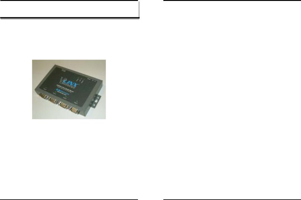
The VLINX Model ESP904 Quad-Port Ethernet Serial Server provides Ethernet to Serial connections for RS-232, RS-422 or RS-485 devices. The serial ports can be accessed over a LAN/WAN using Direct IP Mode, Virtual COM Port, or Paired Mode connections. The 10/100 Mbps Ethernet connection auto-selects 10BaseT or 100BaseTX and indicates the type of connection with a bi-color link light.
Figure 1. The VLINX ESP904 Quad-Port Ethernet Serial Server
Features
•4 multi-interface serial ports - RS-232, RS-422, RS-485; software selectable connections
•10/100 Mbps Ethernet with Auto Selection
•LAN and WAN Communications
•Web Server
•TCP or UDP Client or Server operation - configurable
•Software Support - Windows 98/ME/2000/XP or NT 4.0
•Firmware Upload for Future Revisions/Upgrades
•VLINX ESP Manager Software for Windows - allows easy configuration of Ethernet and serial port settings. For configuration, the
Manual Documentation Number: ESP904-0504 |
Chapter 1 |
1 |
Introduction
ESP904 can be attached to a network or to the Ethernet port of a computer (using a crossover cable). Non-Windows users can configure it in the Console Mode using an RS-232 port, VT100 Terminal Emulation program and an RS-232 crossover cable. Telnet also can be used to access the setup configuration menu.
•Virtual COM Driver Software for Windows - installs a virtual COM port, viewable in the Windows Device Manager under Ports (COM & LPT). Virtual COM port provides access to any of the ports on the ESP904, like any other serial port (legacy, PCI, USB or PCMCIA) on the computer. Any program running on the computer and using Windows-based COM ports can access the serial devices attached to the ESP904. The LAN becomes transparent to the serial device and the software running on the PC.
•Heart Beat Connection - selectable protocol ensures reliable communications in Virtual COM Port or Paired Connection modes. This feature restores the connections if communications are temporarily lost at either end due to loss of power or the Ethernet connection.
Communication Modes
The ESP904 enables communication with serial devices over a LAN or WAN. Serial devices no longer are limited to a physical connection to the PC COM port. They can be installed anywhere on the LAN using TCP/IP or UDP/IP communications. This allows traditional Windows PC software access to serial devices anywhere on the LAN/WAN network.
Direct IP Mode
Direct IP connections allow applications using TCP/IP or UDP/IP socket programs to communicate with the asynchronous serial ports on the ESP904. In this type of application the ESP904 is configured as a TCP or UDP server. The socket program running on the PC establishes a communication connection with the ESP904. The data is sent directly to and from the serial port on the server.
Virtual COM Mode
Use Install Virtual COM to add a driver, to provide a virtual COM port on the computer. The new COM port shows up in the Device Manager. Windows programs using standard Windows API calls are able to interface to virtual COM ports. When a program on the PC opens the new COM port, it communicates with the remote serial device connected to one of the ports on the ESP904.
2 |
Chapter 1 |
Manual Documentation Number: ESP904-0504 |
B&B Electronics Mfg Co Inc – 707 Dayton Rd - PO Box 1040 - Ottawa IL 61350 - Ph 815-433-5100 - Fax 815-433-5104 – www.bb-elec.com B&B Electronics Ltd – Westlink Commercial Park – Oranmore, Galway, Ireland – Ph +353 91-792444 – Fax +353 91-792445 – www.bb-europe.com
B&B Electronics Mfg Co Inc – 707 Dayton Rd - PO Box 1040 - Ottawa IL 61350 - Ph 815-433-5100 - Fax 815-433-5104 – www.bb-elec.com B&B Electronics Ltd – Westlink Commercial Park – Oranmore, Galway, Ireland – Ph +353 91-792444 – Fax +353 91-792445 – www.bb-europe.com
Introduction
After connection, the LAN is transparent to the program and serial device. Applications are able to work just as if the serial device is connected directly to a physical COM port on the computer. The virtual COM port software converts the application’s data into IP packets, sends it across the network to the ESP904, which converts the IP packet back to serial data and sends the data out a serial port located on the ESP904.
To use this mode, the ESP904 must be set to either TCP/server or UDP/server with a designated communication port number. The virtual COM driver is the TCP or UDP client.
Paired Mode
Paired Mode is also called serial tunneling. In this mode any two serial devices that can communicate with a serial link will be able to communicate using two ESP904s and the LAN.
Two ESP904s are connected to a network, one configured as a TCP or UDP client and the other as a TCP/UDP server. When setting up the server the remote IP address section must contain the address of the client. This will allow the client’s IP address to pass the IP address-filtering feature of the server. Conversely, the Remote IP address of the client must contain the server’s IP address. Both communication port numbers must be the same.
Heart Beat
The Heart Beat protocol connection provides a reliable communications connection in Virtual COM Port Mode or with Paired Connection Mode. This feature restores the connection if communications are temporarily lost at either end due to loss of power or Ethernet connection.
Without this feature a device that loses a connection and stops communicating would not be able to reconnect without human intervention. A TCP data connection can be lost when there is a power failure or temporary loss of an Ethernet connection on either the client or server. If a loss occurs the Heart Beat feature will try to reconnect the TCP data connection every five seconds until communications is established again. The Heart Beat feature is available for use in Virtual COM Port Mode and Paired Connection mode. This is not available when using a UDP application.
Manual Documentation Number: ESP904-0504 |
Chapter 1 |
3 |
Introduction
ESP904 Quick Start Guide
Hardware Setup
Required hardware:
•A PC operating on an Ethernet LAN.
•A serial device with a RS-232 interface.
•Network and serial cables, as required.
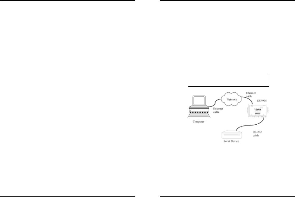
Step 1: Connect the ESP904 to the network using a standard network cable
Step 2: Connect the ESP904 to the RS-232 serial device.
Note:
If the serial device is configured as a DCE use a straight-through serial cable. If the serial device is configured as a DTE use a crossover (null modem) cable.
Figure 2. Quick Start Hardware Setup
Software Installation
Using the CD included with the ESP904, install the VLINX ESP Manager software on the configuring computer.
4 |
Chapter 1 |
Manual Documentation Number: ESP904-0504 |
B&B Electronics Mfg Co Inc – 707 Dayton Rd - PO Box 1040 - Ottawa IL 61350 - Ph 815-433-5100 - Fax 815-433-5104 – www.bb-elec.com B&B Electronics Ltd – Westlink Commercial Park – Oranmore, Galway, Ireland – Ph +353 91-792444 – Fax +353 91-792445 – www.bb-europe.com
B&B Electronics Mfg Co Inc – 707 Dayton Rd - PO Box 1040 - Ottawa IL 61350 - Ph 815-433-5100 - Fax 815-433-5104 – www.bb-elec.com B&B Electronics Ltd – Westlink Commercial Park – Oranmore, Galway, Ireland – Ph +353 91-792444 – Fax +353 91-792445 – www.bb-europe.com
Introduction
ESP904 Configuration
Step 1: From the Windows Start menu, run the ESP Manager, then double click on the Searching Server icon.
Step 2: In the Search Setup box that appears, click on Search all reachable servers, and OK, to find the ESP904 on the network.
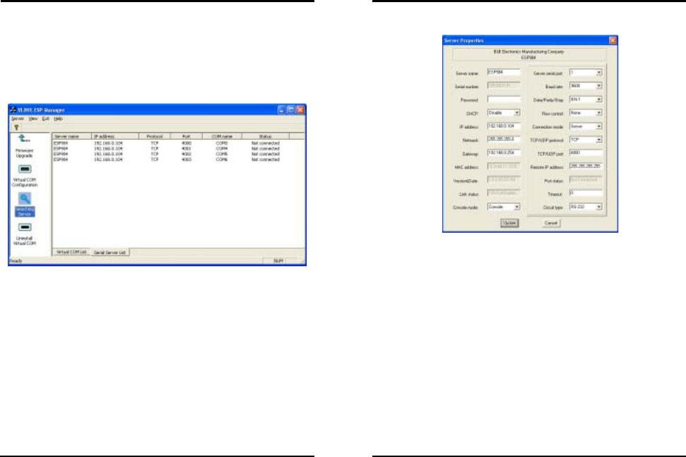
Step 3: A list of servers will appear in the Serial Server List window.
Figure 3. The ESP Manager Window
Introduction
Step 4: Double click on the first ESP904 port on the list (4000) to bring up the Server Properties configuration screen.
Figure 4. The Server Properties Window
Step 5: Change the Server Properties as required.
•Enable DHCP to allow the ESP904 to generate its own IP address
OR
•Obtain appropriate static IP, Netmask and Gateway addresses from your Network Administrator (recommended)
•Set the Console Mode property to RS-232 to match the serial device connected to the ESP904 serial port 1.
•Set Baud Rate, Data/Parity/Stop, and Flow Control to match the configuration of the serial device connected to the ESP904 serial port
Step 6: When the parameters have been set, click on Update.
Step 7: Click on Searching Servers, then re-enter Server Properties to confirm the changes.
Manual Documentation Number: ESP904-0504 |
Chapter 1 |
5 |
6 |
Chapter 1 |
Manual Documentation Number: ESP904-0504 |
B&B Electronics Mfg Co Inc – 707 Dayton Rd - PO Box 1040 - Ottawa IL 61350 - Ph 815-433-5100 - Fax 815-433-5104 – www.bb-elec.com B&B Electronics Ltd – Westlink Commercial Park – Oranmore, Galway, Ireland – Ph +353 91-792444 – Fax +353 91-792445 – www.bb-europe.com
B&B Electronics Mfg Co Inc – 707 Dayton Rd - PO Box 1040 - Ottawa IL 61350 - Ph 815-433-5100 - Fax 815-433-5104 – www.bb-elec.com B&B Electronics Ltd – Westlink Commercial Park – Oranmore, Galway, Ireland – Ph +353 91-792444 – Fax +353 91-792445 – www.bb-europe.com
Introduction
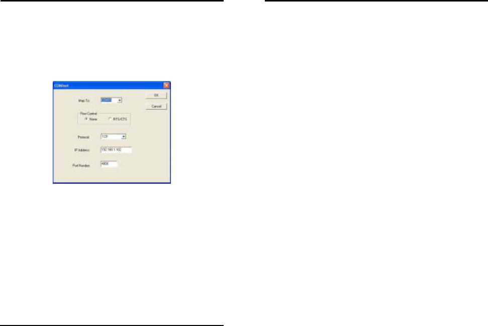
Install Virtual COM Ports on PC
Step 1: From the Windows Start menu, run the Install Virtual COM Ports utility included with the VLINX software,
Step 2: Search for all servers on the network
Step 3: Select the first port (4000) and map it to an unused COM port (e.g. Port 15). Configure it for TCP protocol and the appropriate IP address (determined in the last section).
Figure 5. Configuring the Virtual COM Port
Check Communications
Step 1: From the Windows Start menu, run HyperTerminal
Step 2: Configure HyperTerminal to connect using the COM port configured in the last section (e.g. Port 15).
Step 3: Set Baud Rate, Data/Parity/Stop, and Flow Control to match the configuration of the serial device connected to the ESP904 serial port.
Step 4: Communications with the serial device should now be operational.
Manual Documentation Number: ESP904-0504 |
Chapter 1 |
7 |
Introduction
ESP904 Technical Data
|
Hardware and |
|
ESP904 Serial Server module |
|
|
|
Included |
|
Power Supply: |
12 VDC/1A (tip positive/sleeve negative) |
|
|
Accessories |
|
Power Plug: |
(Area Dependent: North America 120VAC/60Hz, |
|
|
|
|
|
||
|
|
|
|
Europe/United Kingdom 220/240VAC/50Hz) |
|
|
|
|
Manual: |
Paper copy of this manual, PDF available |
|
|
|
|
CD-ROM disc: |
VLINX ESP Manager and Virtual COM Driver |
|
|
|
|
|
software for Windows 98/ME/2000/XP/NT 4.0 |
|
|
Dimensions |
|
ESP904: |
4.5 x 7.3 x 1.1 in (11.4 x 18.5 x 2.9 cm) |
|
|
Power & |
|
Power |
|
|
|
Environment |
|
Requirements: |
12 VDC @ 500 mA |
|
|
|
|
Operating |
|
|
|
|
|
Temperature: |
0 to 50 °C (32 to 122 °F) |
|
|
|
|
Storage |
|
|
|
|
|
Temperature: |
−20 to 60 °C (−4 to 140 °F) |
|
|
|
|
Humidity: |
0 – 90% non-condensing |
|
|
|
|
Approvals: |
CE, FCC |
|
|
Indicators |
|
Power: |
Red LED |
|
|
|
|
Link: |
Yellow or green LED (10BaseT or 100 BaseTX) |
|
|
|
|
Ready: |
Flashing green LED |
|
|
|
|
Serial Ports (4): |
Flashing green LED when data present (see Ch. 2) |
|
|
Connectors |
|
Ethernet: |
Single RJ-45 female |
|
|
|
|
Serial: |
Four - 9 pin D-type male (DB-9M) DTE (all ports |
|
|
|
|
|
are software selectable as RS-232, 422, or 485) |
|
|
|
|
DC Power: |
Ultra-miniature phone jack (2.5mm), Tip (+), |
|
|
|
|
|
Sleeve (−) |
|
|
Serial Interfaces |
|
RS-232(DTE): |
TXD, RXD, RTS, CTS, DTR, DSR, DCD, GND |
|
|
|
|
RS-422: |
TXDB(+), TXDA(−), RXDB(+), RXDA(−), |
|
|
|
|
|
RTS(+), RTS(−), CTS(+), CTS(−) and GND |
|
|
|
|
RS-485: |
Data B (+), Data A (–) and GND |
|
|
|
|
Baud Rate: |
110 bps to 230.4 k bps |
|
|
|
|
Parity: |
None, even, odd |
|
|
|
|
Data Bits: |
7 or 8 |
|
|
|
|
Stop Bits: |
1 or 2 |
|
|
Optional |
|
232NM9 Null Modem Crossover Cable for DTE to DTE connection |
|
|
|
Accessories |
|
DRAD35 DIN Rail mounting clips for 35mm DIN Rail |
|
|
|
|
|
ERS35 one-meter length of steel 35mm DIN Rail |
|
|
|
Memory |
|
Serial Memory: |
8K bytes per port |
|
|
|
|
|
|
|
|
8 |
Chapter 1 |
Manual Documentation Number: ESP904-0504 |
|
|
B&B Electronics Mfg Co Inc – 707 Dayton Rd - PO Box 1040 - Ottawa IL 61350 - Ph 815-433-5100 - Fax 815-433-5104 – www.bb-elec.com B&B Electronics Ltd – Westlink Commercial Park – Oranmore, Galway, Ireland – Ph +353 91-792444 – Fax +353 91-792445 – www.bb-europe.com
B&B Electronics Mfg Co Inc – 707 Dayton Rd - PO Box 1040 - Ottawa IL 61350 - Ph 815-433-5100 - Fax 815-433-5104 – www.bb-elec.com B&B Electronics Ltd – Westlink Commercial Park – Oranmore, Galway, Ireland – Ph +353 91-792444 – Fax +353 91-792445 – www.bb-europe.com

|
|
|
Introduction |
|
|
Introduction |
|
|
|
|
|
|
|
|
|
Network |
LAN: |
10/100 Mbps Auto-detecting 10 BaseT or 100 |
|
|
|
RJ-45 |
|
|
|
|
|
|
|
|
|
Communications |
|
BaseTX |
|
|
|
|
|
|
Reset |
|
2.5 mm Tip (+) |
|
|
||
|
|
|
|
|
female |
|
|
|
|
|
|||||
Protocols |
|
TCP, IP, ARP, DHCP, Telnet, HTTP, UDP, ICMP |
|
|
|
|
|
|
|
|
|
|
|
|
|
Configuration |
Console Mode: |
Using RS-232 with VT100 emulation |
|
|
|
|
|
|
|
|
|
|
|
|
|
Options |
Telnet Mode: |
Using VT100 emulation |
|
|
|
|
|
|
|
|
|
|
|
|
|
|
|
(software for Console Mode or Telnet not |
|
|
|
|
|
|
|
|
|
|
|
|
|
|
|
included, can use HyperTerminal in Windows) |
holemm3.7 |
flatheadscrewmm3 |
countersinkmm5.73 |
|
|
Power |
Link |
Ready |
|
|
mm33.0 |
|
|
|
VLINX ESP Manager: |
- Search for VLINX ESP901 / ESP902 / |
Ethernet |
|
|
1.1 mm |
|
||||||||
|
|
|
|
|
|
|
|
|
|
|
|
||||
|
|
Using Windows 98/ME/2000/XP and NT software |
|
|
|
|
|
|
|
Reset |
DC - In |
|
|
||
|
|
|
|
|
|
|
|
|
|
|
|
|
|
||
|
|
includes: |
|
|
|
|
10/100M |
|
|
|
|
|
|
|
|
|
|
|
|
|
|
|
|
|
|
|
|
|
|
|
|
|
|
|
ESP904 servers on network |
|
|
|
mm |
|
|
|
|
|
|
|
|
|
|
|
- Configure Server Properties |
|
|
|
|
|
|
|
|
|
|
|
|
|
|
|
25.4 mm |
10 mm |
|
12.7 |
|
|
|
|
|
|
43.0 mm |
|
|
|
|
|
- Add/Remove Virtual COM port in |
|
|
|
|
|
|
|
|
||||
|
|
|
Windows |
|
|
|
|
ESP904 4-Port Serial Server |
|
|
|
|
|
||
|
|
|
- Firmware download for future |
|
|
|
|
|
|
|
|
|
|||
|
|
|
hole |
|
|
|
Software Selectable RS-232/422/485 |
|
|
|
|
|
|
||
|
|
|
revisions |
|
|
|
|
|
|
|
|
|
|
|
|
|
|
|
mm |
|
|
|
|
|
|
|
|
|
|
mm |
|
|
|
|
|
|
6.3 mm |
|
|
|
|
|
|
|
|
||
Default Server |
Server Name |
|
ESP904 |
3.7 |
|
|
|
www.bb-elec.com |
|
|
|
11.3 mm |
|
113.7 |
|
|
|
center |
Port 4 |
Port 3 |
|
|
Port 1 |
33.0mm |
|||||||
Settings |
Serial Number: |
|
XXXXXXXXXX |
|
Port 2 |
|
|
||||||||
|
|
|
|
|
|
6.9 mm |
|
|
|
|
|
|
|
|
|
|
Password: |
|
Blank |
|
|
hole |
|
|
|
|
|
|
|
|
|
|
|
|
|
|
|
|
|
|
|
|
|
|
|
||
|
DHCP: |
|
Disable |
|
4.7 mm |
|
|
|
|
|
|
|
|
|
|
|
|
|
|
|
DB-9M |
DB-9M |
DB-9M |
|
|
DB-9M |
|
|
|||
|
IP Address: |
|
192.168.0.1 |
|
25.4 mm = 1 inch |
|
|
|
|
||||||
|
|
|
male |
male |
male |
|
|
male |
|
|
|
||||
|
|
|
|
|
|
|
|
|
|
||||||
|
Net Mask: |
|
255.255.255.0 |
|
|
|
|
|
161.5 mm |
|
|
|
|
|
|
|
Gateway: |
|
192.168.0.254 |
|
|
|
|
|
|
|
|
|
|
|
|
|
|
|
|
|
|
|
|
|
|
|
|
|
|
||
|
MAC Address: |
|
Fixed – see bottom label |
|
11 mm |
|
|
|
|
|
|
|
|
0.29 |
|
|
Port 1 |
|
Console Mode |
|
|
|
|
|
|
|
|
|
|
|
|
|
|
|
|
|
|
|
|
|
|
|
|
|
mm |
||
|
Ports 2, 3, 4 |
|
RS-232 |
|
|
|
|
|
|
|
|
|
|
|
|
|
|
8 mm |
|
|
|
|
|
|
|
|
|
|
|||
|
Baud Rate: |
|
9600 |
|
|
|
|
|
|
|
|
|
|
||
|
|
|
|
|
|
4-40 hex threads |
|
|
|
|
|
|
|||
|
Data/Parity/Stop: |
|
8-N-1 |
|
|
|
|
|
|
|
|
|
|
||
|
|
|
|
|
|
185.0 mm |
|
|
|
|
|
|
|
||
|
Flow Control: |
|
|
|
|
|
|
|
|
|
|
|
|
|
|
|
|
None |
|
|
|
|
|
|
|
|
|
|
|
|
|
|
TCP/UDP Ports: |
|
TCP Port 1 – 4000 |
|
|
|
Figure 6. Dimensional Diagram of the ESP904 |
|
|
||||||
|
|
|
TCP Port 2 – 4001 |
|
|
|
|
|
|
|
|
|
|
|
|
|
|
|
TCP Port 3 – 4002 |
|
|
|
|
|
|
|
|
|
|
|
|
|
|
|
TCP Port 4 – 4003 |
|
|
|
|
|
|
|
|
|
|
|
|
|
Connection Mode: |
Server |
|
|
|
|
|
|
|
|
|
|
|
|
|
|
Remote IP Address: |
255.255.255.255 |
|
|
|
|
|
|
|
|
|
|
|
|
|
Manual Documentation Number: ESP904-0504 |
Chapter 1 |
9 |
10 |
Chapter 1 |
Manual Documentation Number: ESP904-0504 |
B&B Electronics Mfg Co Inc – 707 Dayton Rd - PO Box 1040 - Ottawa IL 61350 - Ph 815-433-5100 - Fax 815-433-5104 – www.bb-elec.com B&B Electronics Ltd – Westlink Commercial Park – Oranmore, Galway, Ireland – Ph +353 91-792444 – Fax +353 91-792445 – www.bb-europe.com
B&B Electronics Mfg Co Inc – 707 Dayton Rd - PO Box 1040 - Ottawa IL 61350 - Ph 815-433-5100 - Fax 815-433-5104 – www.bb-elec.com B&B Electronics Ltd – Westlink Commercial Park – Oranmore, Galway, Ireland – Ph +353 91-792444 – Fax +353 91-792445 – www.bb-europe.com
Installing the VLINX ESP Software
Chapter 2: MAKING THE HARDWARE
CONNECTIONS
Package Checklist
The ESP904 4-port serial server is shipped with the following items included:
9ESP904 Serial Server Module
9Power supply
9This manual
9CD-ROM disc with manual, VLINX ESP Manager and Virtual COM Driver software for Windows 98/ME/2000/XP/NT 4.0
Figure 7. Side View of the ESP904 – when vertically mounted
Manual Documentation Number: ESP904-0504 |
Chapter 2 |
11 |
Installing the VLINX ESP Software
ESP904 Connections, Indicators and Reset Switch
The ESP904 has:
•Seven indicator LEDs
•One Ethernet connector
•A power connector
•A recessed reset switch
•Four serial port connectors
Indicator Lights
Light |
Indication |
Power |
Red - power is applied |
Link |
Yellow – 10BaseT Ethernet connection established |
|
Green – 100BaseTX Ethernet connection established |
Ready |
Flashing Green – system is ready |
Serial (4) |
When set up as a TCP server: |
|
Steady Green - client has made a connection, |
|
communications starting |
|
Flashing Green – data present at serial port |
|
Light off – connection closed |
|
When setup in UDP mode: |
|
Steady Green (all ports) |
|
Flashing Green – data is being transmitted |
Ethernet Connector
The ESP904 has a standard RJ-45 receptacle mounted in the top edge of the chassis. The ESP904 can be connected to an Ethernet hub, switch, or wall plate using a standard straight-through RJ-45 (male) Ethernet cable. To connect directly to an RJ45 Ethernet port on a PC or laptop a crossover Ethernet cable must be used.
Note:
Refer to Appendix D for details on Network Cables
12 |
Chapter 2 |
Manual Documentation Number: ESP904-0504 |
B&B Electronics Mfg Co Inc – 707 Dayton Rd - PO Box 1040 - Ottawa IL 61350 - Ph 815-433-5100 - Fax 815-433-5104 – www.bb-elec.com B&B Electronics Ltd – Westlink Commercial Park – Oranmore, Galway, Ireland – Ph +353 91-792444 – Fax +353 91-792445 – www.bb-europe.com
B&B Electronics Mfg Co Inc – 707 Dayton Rd - PO Box 1040 - Ottawa IL 61350 - Ph 815-433-5100 - Fax 815-433-5104 – www.bb-elec.com B&B Electronics Ltd – Westlink Commercial Park – Oranmore, Galway, Ireland – Ph +353 91-792444 – Fax +353 91-792445 – www.bb-europe.com
Installing the VLINX ESP Software
Power Connector
Plug the ultra-miniature phone plug from the included power supply into the power jack and then plug the supply in. When power is applied the Red power light will illuminate. The tip of the power plug is positive; the sleeve is negative.
Reset Button
This switch resets the unit, similar to the effect of removing/applying power. The Reset switch is recessed to avoid accidental operation. To reset the unit, insert a small plastic tool, press lightly and hold for 3 seconds. The Link and Ready lights will go out and then come back on.
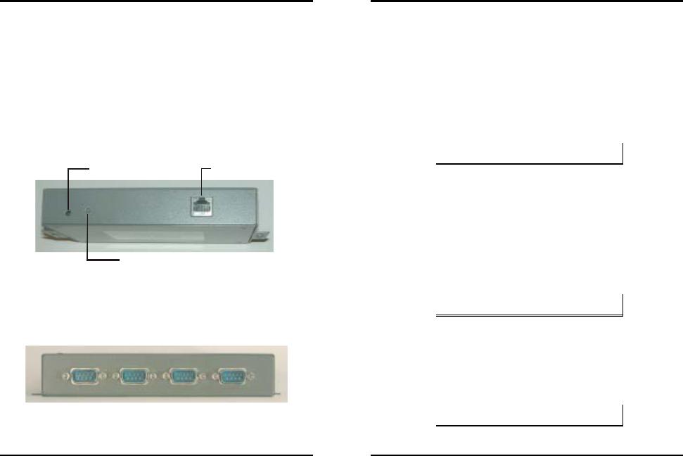
Power Connection |
RJ-45 Receptacle |
Reset
Figure 8. Top View of the ESP904
Serial Ports
The ESP904 has four serial ports, each configurable through software as RS232, RS-422 or RS-485 interfaces. The connectors are DTE DB-9M.
|
|
Serial Port |
|
4 |
3 |
2 |
1 |
Figure 9. The ESP904 Serial Port Connectors
Manual Documentation Number: ESP904-0504 |
Chapter 2 |
13 |
Installing the VLINX ESP Software
Serial Port Operational Modes
Using the ESP Manager or the Console Mode Configuration Menu each serial port can independently be configured as RS-232 Mode, RS422 Mode or RS-485 Mode. Port 1 of the ESP904 also can be placed in Console Mode,
Upgrade Mode or Default Mode. Port 1 default setting is Console Mode.
Default Mode
When Default Mode is selected and the Server Properties are Updated (Saved) all the configuration settings return to their default values. The default settings for the ESP904 serial ports are: Console Mode for Port 1; RS-232 mode for Ports 2, 3 and 4.
Note:
Refer to Chapter 5 for details on Server Configuration settings
Console Mode
In Console Mode the ESP904 Configuration Menu can be accessed from a computer by connecting its RS-232 serial port to the ESP904’s Port 1. Since the computer is a DTE device, and the ESP904 serial ports are configured as DTEs (with DB-9M connectors), a null modem crossover cable must be used.
In Console Mode the default serial port settings are: 9600 baud, 8 data bits, No parity, and 1 stop bit. From Windows, HyperTerminal with VT100 terminal emulation can be used for Console Mode configuration.
Note:
Refer to Chapter 9 for details on Console Mode
Upgrade Mode
Using a similar connection setup to that used in Console Mode, firmware for the ESP904 can be updated by connecting the ESP904 to a computer via Port 1, using RS-232. (Upgrading also can be done by communicating with the ESP904 over the network connection, using the ESP Manager software and a virtual COM port mapped to the ESP904 Port 1.)
Note:
Refer to Chapter 8 for details on Upgrade Mode
14 |
Chapter 2 |
Manual Documentation Number: ESP904-0504 |
B&B Electronics Mfg Co Inc – 707 Dayton Rd - PO Box 1040 - Ottawa IL 61350 - Ph 815-433-5100 - Fax 815-433-5104 – www.bb-elec.com B&B Electronics Ltd – Westlink Commercial Park – Oranmore, Galway, Ireland – Ph +353 91-792444 – Fax +353 91-792445 – www.bb-europe.com
B&B Electronics Mfg Co Inc – 707 Dayton Rd - PO Box 1040 - Ottawa IL 61350 - Ph 815-433-5100 - Fax 815-433-5104 – www.bb-elec.com B&B Electronics Ltd – Westlink Commercial Park – Oranmore, Galway, Ireland – Ph +353 91-792444 – Fax +353 91-792445 – www.bb-europe.com
 Loading...