


AA-929

ModelAA-929
REMOTECONTROL
TWO WIRE ALARM SECURITY SYSTEM
INSTALLATIONGUIDE&OWNER’SMANUAL
GUIDE D’INSTALLATION ET MANUEL DE L’UTILISATEUR
DE L’ANTIVOL TÉLÉCOMMANDÉ À DEUX FILS
SISTEMA DE SEGURIDAD CON ALARMA BIFILAR A
CONTROL REMOTO
GUÍA DE INSTALACIÓN Y MANUAL DEL PROPIETARIO

CONGRATULATIONS On the purchase of your new Audiovox Alarm System. Taking a few minutes to read this
installation and owners guide will provide you with the detailed information concerning all the features of your new
alarm system.
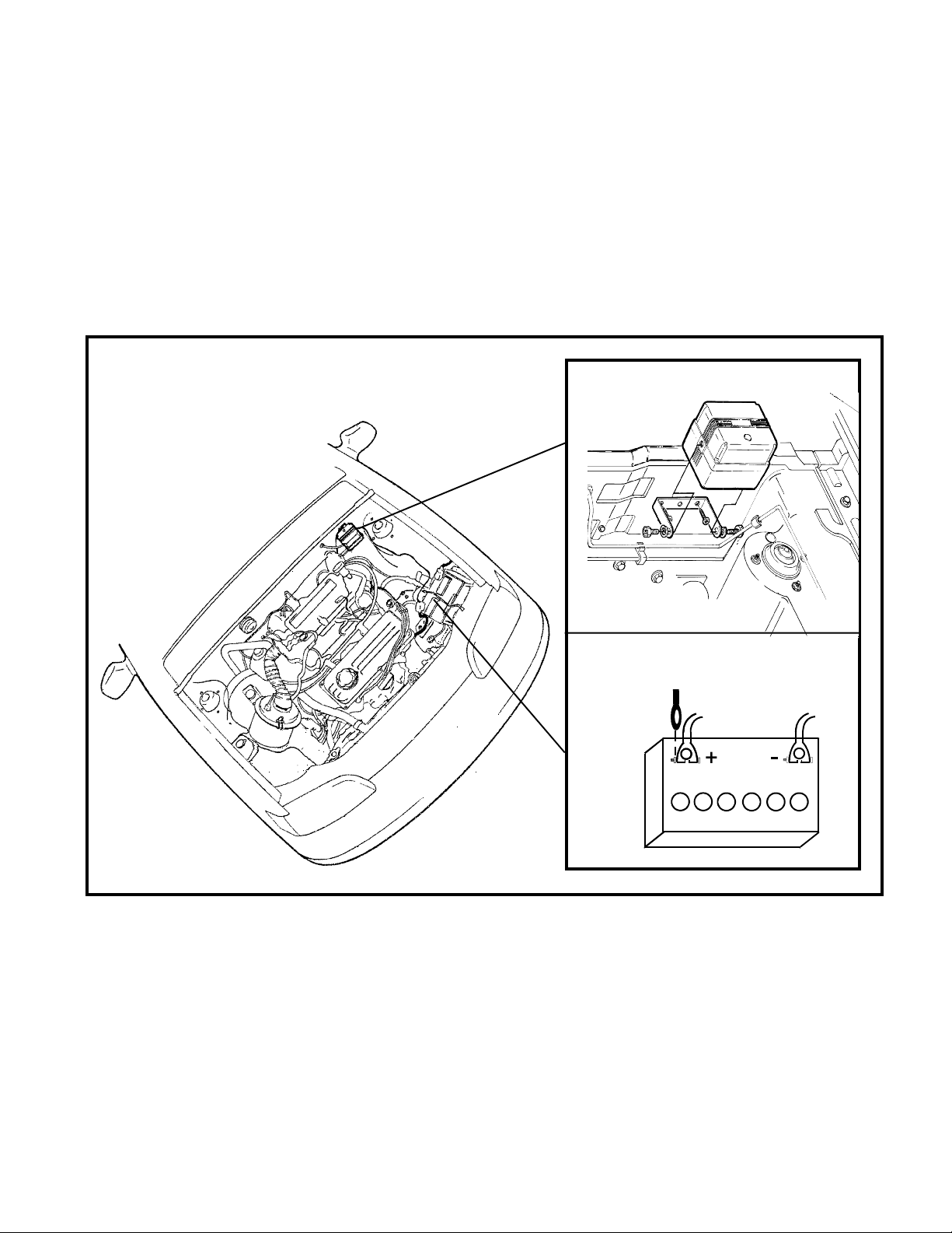
MOUNTING THE SIREN:
1. Choose a location in the engine compartment that is
away from hot and moving parts, considering the Red
wire length which must connect to a battery positive
source. Mount the siren high enough toprevent access
from below the vehicle. Typical locations are the inner
fender well or the rear firewall.
2. Once you've selected a location, inspect behind the
area to insure that drilling the two holes required to
mount the bracket will not penetrate wiring or fluid lines.
3. Using the siren bracket as a template, mark the two
mounting holes with a scribe or punch at your chosen
location and drill two 3/16" holes on the pre-selected
marks.
4. Using the two 1/4" x 1" screws supplied, secure the
siren mounting bracket in place.
5. Mount the siren to the bracket as shown using the two
nuts, washers, and lock washers provided. Point the
siren horn (front) downward to allow the sound to easily
escape the engine compartment.
Note: If the bracket is mounted to a grounded metal sur-
face, secure the Black siren ground when mounting the siren to the bracket. If the bracket is
mounted to plastic or a non grounded surface, connect the Black siren ground wire as described in
the following section.
WIRING THE SIREN:
RED:
Connect the Red wire of the siren to Positive post of the
battery using the 5/16" ID ring terminal as shown. If your
vehicle has side mount main battery terminals, it will be
necessary to locate an alternate + 12 volt constant source.
If you are unfamiliar with automotive wiring, it would be best
to consult your dealer before making this connection.
BLACK:
Connect the Black siren wire to a clean grounded metal
part of the vehicle. Drill a 1/8" hole in your chosen mounting location, scrape off any paint or grease from the area
and secure the ground wire with the 1/4" ring terminal and
screw provided.
GREEN LOOP:
The Green loop wire controls the voltage sensor. Cutting
this wire loop will prevent the circuits voltage sensor from
detecting voltage drops such as the interior light turning on
when the door is opened. This wire should remain connected unless your vehicle has circuitry that remains powered when the vehicle is turned off. Examples of vehicle
circuits that will necessitate cutting the Green loop wire
are automatic load leveling shocks, electric analog clocks,
on board computers that update their information on a regular
basis. If you experience false triggers after installation of
your alarm system, it may be necessary to delete the volt-
-1-

age sensor. In such situations, the level of protection is
minimized and reliant strictly on the vibration detector. It
may be necessary to increase the sensitivity of the vibration sensor. To do so see the section on adjusting the
shock sensors for optimum results.
NOTE: If the vehicle battery is disconnected, or the alarm loses
power, the transmitters WILL NOT remain in memory.
In such instances, re-programming the transmitters is
necessary to operate the alarm. To re-program the
transmitters, repeat the above procedure.
WHITE LOOP:
The White loop wire controls the voltage sensors arming
delay. Vehicles with circuits that remain on after the ignition switch is turned off will require a delay before arming.
Cutting the white loop wire will delay the voltage sensor's
arming delay from 3 seconds to 5 minutes. This additional delay will allow any active circuit in the vehicle to
turn off before the voltage sensor is capable of detecting
voltage drops. This will allow you to arm the unit immediately when exiting the vehicle, once the vehicles electrical
circuit stabilizes, the alarm will fully arm sometime later.
PROGRAMMING THE TRANSMITTERS:
Your AA-929 Security System will learn up to two Audiovox
code learning transmitters. To program the transmitters,
disconnect power to the alarm for 10 seconds. Reconnect
power and within 10 seconds, press button #1 of the first
transmitter to be programmed. The siren will chirp indicating the transmitter has been learned. Within 5 seconds of
the first learned transmitter, press button #1 of the second
transmitter to be programmed. The siren will chirp indicating the second transmitter has been learned.
OPERATING YOUR SYSTEM:
ARMING:
1. Exit your vehicle, and close all entry points.
2. Press button #1 of your keychain transmitter 1 time. The
siren will emit a single tone indicating that the system is
armed.
NOTE: Pressing the arming button twice within 3 seconds will
allow the unit to arm without the shock sensor. This
will be indicated by a single chirp tone followed by a
single higher pitch chirp tone. When operating in this
mode, the only detection means will be the voltage
sensor. The next normal arming of your system will re-
instate the shock sensor.
DISARMING:
1. As you approach your vehicle, press button #1 of your keychain
transmitter 1 time. The siren will emit two chirps indicating
that the system is disarmed. You may now enter and operate your vehicle in a normal manner.
NOTE: If you heard four chirp tones upon disarm, this indicates
that the system had been triggered in your absence.
Carefully inspect your vehicle for break in or physical
damage.
-2-

If your system fails to operate as above:
1. Check and insure that your keychain transmitter is operating properly, and that the small LED on the transmitter illuminates when a transmitter button is depressed.
2. Check and insure that the Red wire of the system is
connected to a +12 volt battery source.
3. Be certain that the transmitters are programmed into
your alarm system. If power had been disconnected
from the alarm or the vehicle main battery had been
disconnected, it is necessary to re-program the transmitters. See transmitter programming section of this
manual.
TESTING THE VOLTAGE SENSOR:
1. Arm the alarm system by pressing button #1 of a pro-
grammed transmitter one time. The siren will chirp once
confirming that the system is armed.
2. Wait 4 seconds to allow the unit to stabilize.
3. Open any light activated entry point, the siren will imme-
diately trigger.
4. Turn the alarm system off by pressing button #1 of a
programmed transmitter one time.
5. Repeat the above procedure for each light activated en-
try point.
If the unit fails to operate review the following section concerning voltage sensor adjustment.
VOLTAGE SENSOR:
In most instances, connecting the Red siren wire to the
vehicle battery will provide adequate voltage sensing. If
your vehicle does not trigger when the door is opened and
the interior light turns on, it may be necessary to increase
the voltage sensor's level of detection. Before making this
wiring change, confirm that the interior light is in good working order and illuminates when any door is opened. If your
interior light works properly, and the unit does not trigger,
the Red wire will have to connect to a +12 volt source closer
to the interior light. This may necessitate moving the Red
wire to the interior of the vehicle and connecting to the
interior light fuse. Routing the Red wire through a firewall
grommet and connecting to the interior light fuse may be
beyond the scope of your automotive wiring experience. If
you are uncertain of this procedure, consult your dealer or
qualified mechanic before attempting to re-wire the voltage
sensors through the firewall to increase the voltage sensor's
level of detection.
TESTING THE SHOCK SENSOR:
NOTE: The shock sensor incorporated in your AA-929 se-
curity system operates on two levels in any sensitivity range. The warn away (pre-detect) stage
operates at 30% less shock (vibration) than the
full trigger stage.
1. Arm your security system and allow the unit to stabilize.
-3-

2. Strike the windshield support pillar with the palm of your
hand, the unit will emit a few short chirps from the siren.
This is the warn away (pre-detect) stage.
3. Striking the support pillar firmly will cause the siren to
sound. This is the full trigger stage.
4. Repeat the above procedure from various support areas
of your vehicle, Bumpers, B Pillars, etc.
If your system fails to operate as described, review the
following section concerning shock sensor adjustment.
SHOCK SENSOR ADJUSTMENT:
The shock sensor of the AA-929 security system is electronically adjusted and is capable of 8 different sensitivity
levels. To adjust or change the setting of your shock sensor disarm the system and within 8 seconds, simultaneously
press both buttons of your transmitter until the siren emits
a low tone. This indicates that the unit is ready to accept
a sensitivity level change. Press button #2 of your transmitter to make adjustments. The siren will emit a tone
synonymous with the changing levels. The lower the tone,
the lower the setting, the higher the tone, the higher the
setting. While in the adjustment mode, strike a support
pillar of the vehicle, the unit will emit a 2 second tone indicating your setting. The system will allow you to keep this
setting or make further adjustments. Once you've reached
the desired level, press button #1 to lock in your setting.
The siren will emit two high chirps to confirm your setting
is locked. Follow steps 1-4 above to test the sensitivity
level change.
INSTALLING THE WARNING DECALS:
Once you've confirmed the operation of your security system, you may elect to install the security systems warning
decals. Typically these decals are installed on the lower left
of the driver side and lower right of the passenger side windows as shown. Remove the decal backing paper and hold
the ends of the decal toward you. This will cause the center
to bend toward the window. Place the center of the decal on
the window and roll the sides out one at a time. This will
insure no air bubbles get under the decal when affixing it to
the window. Once in place, smooth out the entire label pressing it firmly to the window.
-4-

OPERATION AT A GLANCE:
TRANSMITTER OPERATION SYSTEM RESPONSE
PRESS BUTTON #1 1 TIME
PRESS BUTTON #1 2 TIMES
PRESS BUTTON #1 FOR 3 SECONDS
PRESS BOTH BUTTONS FOR 2
SECONDS
ARMS OR DISARMS ALARM
DELETE SHOCK SENSOR
FUNCTION
PANIC MODE
SHOCK ADJUST MODE
AUDIBLE STATUS INDICATIONS:
1 CHIRP = SYSTEM ARMED
2 CHIRPS = SYSTEM DISARMED
4 CHIRPS = SYSTEM DISARMED AND HAD BEEN TRIGGERED
WIRE LOOP CONFIGURATION
GREEN
WHITE
VOL TAGE SENSOR
OPERA TIONAL
3 SECOND VOLTAGE
SENSE DELAY
-5-
PRE - CONDITION
SYSTEM MUST FIRST BE
DISARMED
SYSTEM MUST FIRST BE
DISARMED
OPEN (CUT)WIRE LOOP CLOSED (NOT CUT)
VOLTAGE SENSOR
NON OPERATIONAL
5 MINUTE VOLTAGE
SENSE DELAY
SIMPLE TWO STEP INSTALLATION
MOUNT THE SIREN
1
CONNECT POWER AND GROUND
2
-6-

12 MONTH LIMITED WARRANTY
Applies to control modules, relays, transmitters, sensors, and sirens.
AUDIOVOX CORPORATION (the Company) warrants to the original retail purchaser of this product that should this product or any part thereof,
under normal use and conditions, be proven defective in material or workmanship within 12 months from the date of original purchase, such
defect(s) will be repaired or replaced (at the Company's option) without charge for parts and repair labor.
To obtain repair or replacement within the terms of this Warranty, the product is to be delivered with proof of warranty coverage (e.g. dated
bill of sale), specification of defect(s), transportation prepaid, to an approved warranty station or the Company at the address shown below.
This Warranty does not cover costs incurred for removal or reinstallation of the product, or damage to vehicle electrical systems.
This Warranty does not cover batteries nor apply to any product or part thereof which, in the opinion of the Company, has suffered or been
damaged through alteration, improper installation, mishandling, misuse, neglect, accident, or by removal or defacement of the factory serial
number/bar code label(s).
This Warranty is in lieu of all other express warranties or liabilities. ANY IMPLIED WARRANTIES, INCLUDING ANY IMPLIED WARRANTY OF
MERCHANTABILITY,SHALLBE LIMITEDTOTHE DURATIONOFTHIS WRITTENWARRANTY. ANY ACTIONFORBREACH OFANYWARRANTY
HEREUNDERINCLUDINGANY IMPLIED WARRANTYOFMERCHANTABILITY MUST BEBROUGHTWITHIN A PERIODOF30 MONTHSFROM
DATEOFORIGINALPURCHASE. IN NO CASESHALLTHECOMPANY BE LIABLEFORANYCONSEQUENTIAL OR INCIDENTALDAMAGES
FOR BREACHOFTHISORANYOTHER WARRANTY, EXPRESS OR IMPLIED, WHATSOEVER. No person or representative isauthorizedto
assume for the Company any liability other than expressed herein in connection with the sale of this product.
TheCompanydoesnot warrant thatthisproductcannot be compromisedorcircumvented. THE EXTENTOFTHE COMPANY'S LIABILITY UNDER
THISWARRANTYIS LIMITEDTOTHEREPAIR ORREPLACEMENTPROVIDED ABOVEAND,IN NO EVENT,SHALLTHE COMPANY'SLIABILITY
EXCEEDTHEPURCHASE PRICEPAIDBY PURCHASERFORTHEPRODUCT.
Some states do not allow limitations on how long an implied warranty lasts or the exclusion or limitation of incidental or consequential damage
so the above limitations or exclusions may not apply to you. This Warranty gives you specific legal rights and you may also have other rights
which vary from state to state.
U.S.A. : AUDIOVOX CORPORATION, 150 MARCUS BLVD., HAUPPAUGE, NEW YORK 11788 (516) 231-6051
CANADA: CALL 1-800-645-4994 FOR LOCATION OF WARRANTY STATION SERVING YOUR AREA
FormNo.128-4118D1
-7-
 Loading...