


1 |
USER’S MANUAL |
|
|
|
Part 2 |
Four-Line Intercom
Speakerphone 944
Please also read
Part 1 – Important
Product Information
AT&T and the globe symbol are registered trademarks of AT&T Corp. licensed to Advanced American Telephones.
BEFORE YOU BEGIN....................... |
2 |
Glossary............................................... |
3 |
Features List......................................... |
4 |
Audible Signals .................................... |
5 |
INSTALLATION ............................... |
6 |
Table/Desk Installation........................ |
6 |
Wall Installation................................... |
8 |
Convenience Ports ............................ |
12 |
FEATURE SET UP .......................... |
13 |
Set the Time/Date.............................. |
14 |
Assign an Extension Number |
|
to Your Phone ................................ |
14 |
Turn the Ringer On or Off |
|
for Each Line.................................. |
14 |
Select the Ringer Type....................... |
15 |
Set Delay Ring ................................... |
15 |
Turn Line Usage On or Off |
|
for Each Line.................................. |
15 |
Assign the Prime Line |
|
(Line Preference) .......................... |
16 |
Assign the Line Group |
|
for this Phone ................................ |
16 |
Turn Auto-Mute On or Off................. |
16 |
Set Audio Mode.................................. |
17 |
Set the Dial Mode .............................. |
17 |
Set the Flash Time ............................. |
17 |
Turn Hold Reminder On or Off ........ |
17 |
Set Your Phone to be the Centrex |
|
Console Phone .............................. |
18 |
Program the Centrex Console |
|
Delayed Ring Time......................... |
18 |
Erase All Settings and Return |
|
the Phone to Default Settings........ |
18 |
TELEPHONE OPERATION ............... |
19 |
Making or Answering a Call ............... |
20 |
Timer .................................................. |
21 |
Pause................................................... |
21 |
Call Privacy......................................... |
22 |
Do Not Disturb................................... |
22 |
Line-in-Use Lights ............................... |
23 |
Volume................................................ |
23 |
Redial................................................. |
23 |
Auto Redial ........................................ |
24 |
Hold .................................................... |
24 |
Switch Between Lines ........................ |
24 |
Mute..................................................... |
25 |
CONTENTS |
|
Flash..................................................... |
25 |
Temporary Tone Dialing...................... |
25 |
Conference Calls ................................. |
25 |
Transfer a Call..................................... |
26 |
Low Battery Indicator ........................ |
26 |
SPEED DIAL OPERATION............... |
27 |
Storing a Number in |
|
a Speed Dial Location ..................... |
28 |
Reviewing a Speed Dial Entry ............ |
28 |
Making a Speed Dial Call.................... |
28 |
INTERCOM OPERATION ................. |
29 |
Basic Intercom Operations................. |
30 |
Making an Intercom Call with |
|
the Handset ................................... |
30 |
Making an Intercom Call with the |
|
Speakerphone or Headset ............. |
31 |
Answering an Intercom Call ............ |
31 |
Making a Single-phone Page.............. |
31 |
Answering a Single-phone Page ......... |
31 |
Switching Between an Intercom |
|
Call and a Single-phone Page......... |
31 |
Ending an Intercom or Page Call ........ |
31 |
Paging All Phones ............................... |
32 |
Answering a System-wide Page .......... |
32 |
Making an Intercom |
|
Conference Call ............................. |
32 |
Room Monitor .................................... |
32 |
ADDING A FAX MACHINE............... |
33 |
Using a Fax Switch ............................. |
33 |
IN CASE OF DIFFICULTY ................ |
34 |
EXPANDING THE PHONE SYSTEM .. 36
Line Groups........................................ |
36 |
Private Lines ....................................... |
37 |
CENTREX OPERATION ................... |
38 |
Setup Checklist................................... |
38 |
Enabling the Console Phone.............. |
38 |
Console Operation ............................. |
38 |
Setting Ring Delay Duration................. |
39 |
Answering a Delayed Ring .................. |
39 |
Picking Up Another Station’s Line..... |
39 |
INDEX ........................................... |
40 |
1
BEFORE YOU BEGIN
This 944 telephone is fully compatible with any AT&T Four-Line Intercom Speakerphone 964 or 955 units you may have installed. You can use up to a total of 12 944/955/964 units together as extensions on your phone system.
•Check to be sure your box contains:
1Telephone
1Handset
1Handset cord
1Mounting base
2Seven-foot line cords
1Eight-inch line cord
1Power adapter
1Warranty insert
19V battery
1User’s Manual
•You must have a modular telephone jack and an electrical outlet not controlled by a wall switch near where you’re installing the phone.
•The total length of telephone wiring used in this system is important. If the total length of telephone wiring is more than
600 feet, you may need to use a special filter device. You can call 1 800 222–3111 for information about this filter. You’ll need to contact a professional to install this filter.
•Identify the number of phone lines you’ll use.
•Plan the layout of your phone system.
•All connected phones must have the same Line 1 phone number for the Intercom and Page features to work.
•Assign a different Intercom Extension Number (11 through 22) to each system phone. You’ll need to do this individually at each telephone.
•Decide if you want a private line. A private line does not appear on all connected phones.
•Choose your setting for each feature. You will need to program the features during installation (see “Features List”).
2
BEFORE YOU BEGIN
Glossary
Centrex Service: A special subscriber service which may be available from your local telephone company for a fee. The 944 telephone can be used with Centrex Service.
DND: When activated the Do Not Disturb feature prevents interruptions during a call.
Line Group: A group of system phones sharing some lines within a multi-phone system.
Navigation buttons: These are the buttons used when programming your 944 phone and for scrolling through feature options (+, -, >, <,
E, S).
Phone System: Two or more 944/955/964 phones combined into an interacting system of shared lines. You can have up to 12 phones and up to 15 telephone lines in the system.
Prime Line: This is the line on your phone you designate to be selected automatically when you lift the handset, press K, or press h.
System Phone: Any 944, 955 or 964 phone in your phone system.
3
BEFORE YOU BEGIN
Features List
NOTE: An * indicates the default setting for each feature.
NOTE: One ring is equal to about six seconds, two rings equals twelve seconds, and so on.
Feature |
Function |
Setting Option(s) |
|
|
|
TIME/DATE |
Set time and date |
01:00AM 01/01 Sunday* |
|
|
|
EXTENSION NO |
Assign extension number for this |
11-22* |
|
phone |
|
|
|
|
RINGER ON/OFF |
Turn ringer on or off for each line |
On* or Off |
|
|
|
RINGER TYPE |
Select ring pattern for this phone |
Type 1*, 2, 3, 4 |
|
|
|
DELAY RING |
Select desired time to delay |
Off*, 2, 4, 6, ... 30 seconds |
|
Central Office ring |
|
|
|
|
LINE USAGE |
Turn line usage on or off for |
On* or Off |
|
each line |
|
|
|
|
PRIME LINE |
Assign a line on this phone to be |
Line 1*, 2, 3, 4 |
|
selected automatically when you |
|
|
lift the handset, press K, |
|
|
or press h |
|
|
|
|
LINE GROUP |
Assign your phone to a Line |
Line Group 4*-15 or PRV |
|
Group |
(private) |
|
|
|
AUTO-MUTE |
Turn Auto-Mute on or off |
On* or Off |
|
(sounds at this extension will be |
|
|
heard automatically when paged) |
|
|
|
|
AUDIO MODE |
Choose default mode for calls |
Speakerphone* or Headset |
|
connected with handset in cradle |
|
|
|
|
TONE/PULSE |
Set dial mode for touch-tone or |
Tone* or Pulse |
|
dial pulse (rotary) dialing |
|
|
|
|
FLASH TIME |
Set length of signal sent when |
0.3 seconds - 0.9 seconds |
|
you press F |
0.7 seconds* |
|
|
|
HOLD REMINDER |
Turn audible reminder that a call |
On* or Off |
|
at this extension is on hold on |
|
|
or off |
|
|
|
|
CONSOLE |
Specify whether your phone is |
On or Off* |
|
the Centrex Console phone for |
|
|
your phone system |
|
|
|
|
CSL DELAY RING |
Set time to delay ring for Centrex |
Off*, 2, 4, 6, ... 30 seconds |
|
Console phone |
|
|
|
|
RESET ALL!!! |
Return all settings to |
(Defaults) |
|
default settings |
|
|
|
|
4
BEFORE YOU BEGIN
Audible Signals
When you hear: |
It means: |
|
|
A rapid double-ring pattern, |
You have an incoming intercom call. |
repeating |
|
|
|
Long single ring, repeating |
You have an incoming transferred call. |
|
|
Short single ring, repeating |
The extension number you just programmed has |
|
already been assigned. Choose another number for |
|
this extension. |
|
|
Short single tone, repeating |
The extension you are calling is in DND mode. |
|
|
Long single tone, repeating |
The extension you are calling is busy. |
|
|
5
INSTALLATION
NOTE: If you are installing multiple phones in your telephone system, you must install and program one set at a time. If more than one extension is assigned the same extension number, a repeating short ring (error ring) will sound at all extensions. Reassign extension numbers, being sure that each extension has a different number from 11 to 22 (see “Assign an Extension Number to Your Phone” in FEATURE SET UP).
Table/Desk Installation
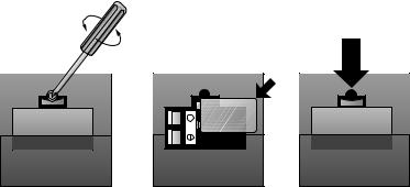
1Install one 9V battery.
•Press in on the tabs and remove the telephone base.
•Use a small Phillips head screwdriver to remove the screw and open the battery door.
•Insert the 9V battery (included), and replace the screw to close the battery door.
•Replace the telephone base.
NOTE: The battery retains telephone memory in the event of a power failure. If power fails and a working battery is installed, all four lines of this phone will work only to answer calls with the handset or headset, and dial calls using the key pad and the Speed Dial or Redial features. No other features will work until power is restored.
6

INSTALLATION
2Connect the telephone line cords to the telephone.
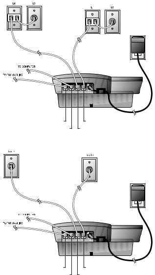
•Four One-Line Jacks (To use this installation option, you’ll need to purchase two two-line adapters. Adapters are available at retail stores or by calling 1 800 222–3111.)
Two-line |
Adapters |
Modular
Telephone Jacks
Lines 3 and 4
Modular |
Telephone Jacks |
Lines 1 and 2 |
Standard |
Electrical |
Outlet |
Power Cord
Telephone |
|
Line Cords |
Telephone Jack L1/L2 |
|
|
|
Telephone Jack L3/L4 |
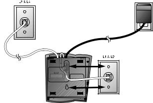
•Two Two-Line Jacks
Modular
Telephone Jack
Lines 3 and 4
Modular |
Standard |
Telephone Jack |
Electrical |
Lines 1 and 2 |
Outlet |
Power Cord
Telephone
Line Cords
Telephone Jack L1/L2
Telephone Jack L3/L4
7

INSTALLATION
3Connect the handset cord.
Plug one end of the coiled handset cord into the jack on the left side of the phone. Plug the other end into the handset, and hang up.
4Connect the power adapter.
Use only the power adapter provided with this product. To obtain a replacement, call 1 800 222–3111.
Plug one end of the power adapter into the jack labeled POWER on the back of the phone. Plug the other end into a standard electrical outlet not controlled by a wall switch.
NOTE: The screen will display POWERFAIL the first time you plug in the phone. Press any key to clear the screen.
5Check for dial tone.
Lift the handset and listen for a dial tone. If you cannot hear a dial tone, turn to IN CASE OF DIFFICULTY.
6Initialization.
As soon as you connect the power cord, the phone runs a quick self-test and the screen displays Initializing.. for about seven seconds. When the test is complete, the phone enters an initial setup mode and the screen displays press PROG to setup your phone. See FEATURE SET UP beginning on page 13.
NOTE: The phone will run through this same initialization anytime it is reconnected to AC power (i.e., after a power failure or when the unit has been unplugged).
Wall Installation
1Reverse the handset tab.
Hold down the switchhook, then pull the tab out and rotate it 180 degrees. Push the tab down into the grooves so it settles into position.
8

INSTALLATION
2Install one 9V battery.
•Press in on the tabs and remove the telephone base.
•Use a small Phillips head screwdriver to remove the screw and open the battery door.
•Insert the 9V battery (included), and replace the screw to close the battery door.
•Replace the telephone base.
NOTE: The battery retains telephone memory in the event of a power failure. If power fails and a working battery is installed, all four lines of this phone will work only to answer calls with the handset or headset, and dial calls using the keypad and the Speed Dial or Redial features. No other features will work until power is restored.
3Connect the telephone line cords to the telephone.
Please refer to line cord connection instructions in Step 2 of “Table/Desk Installation’ on page 7.
4Turn the base, as shown, and attach it to the bottom of the phone.
9
INSTALLATION
5Connect the handset cord.
Plug one end of the coiled handset cord into the jack on the left side of the phone. Plug the other end into the handset, and hang up.
6Connect the power adapter to the telephone.
Use only the power adapter provided with this product. To obtain a replacement, call 1 800 222–3111.
Plug one end of the power adapter into the jack labeled POWER on the back of the phone.
NOTE: The screen will display POWERFAIL the first time you plug in the phone. Press any key to clear the screen.
7Check for dial tone.
Lift the handset and listen for a dial tone. If you cannot hear a dial tone, turn to IN CASE OF DIFFICULTY.
8Mount the phone on the wall.
• Four One-Line Jacks
Modular |
Standard |
Telephone Jacks |
Electrical |
Lines 3 and 4 |
Outlet |
|
Power Cord |
Modular Telephone Jacks
Lines 1 and 2
10
|
INSTALLATION |
• Two Two-Line Jacks |
|
Modular |
Standard |
Telephone Jack |
Electrical |
Lines 3 and 4 |
Outlet |
|
Power Cord |
Modular
Telephone Jack
Lines 1 and 2
9Plug the power adapter into a standard electrical outlet not controlled by a wall switch.
10Initialization.
As soon as you connect the power cord, the phone runs a quick self-test and the screen displays Initializing.. for about seven seconds. When the test is complete, the phone enters an initial setup mode and the screen displays press PROG to setup your phone. See FEATURE SET UP beginning on page 13.
NOTE: The phone will run through this same initialization anytime it is reconnected to AC power (i.e., after a power failure or when the unit has been unplugged).
11
INSTALLATION
Convenience Ports
If you want to connect another device (such as a modem or fax machine) to the wall jack, you can use the jacks on the phone labeled AUX. These convenience ports use Lines 3 and 4; a call picked up on Line 3 or 4 at another extension may interrupt fax, modem, or message transmission.
•Four One-Line Jacks
Modular
Telephone Jacks
Lines 3 and 4 with Two-line Adapter
Telephone Jack Aux L4
Telephone Jack Aux L3
Modular Telephone Jacks
Lines 1 and 2 with
Two-line Adapter
Standard
Electrical
Outlet
Power Cord
Telephone Jack L1/L2 |
Telephone Jack L3/L4
•Two Two-Line Jacks
Modular |
Modular |
|
Telephone Jack |
||
Telephone Jack |
||
Lines 3 and 4 |
||
Lines 1 and 2 |
||
|
Telephone Jack Aux L4
Telephone Jack Aux L3
Standard
Electrical
Outlet
Power Cord
Telephone Jack L1/L2 |
Telephone Jack L3/L4
12
 Loading...