


1 |
USER’S MANUAL |
|
|
|
Part 2 |
Four-Line Intercom/
Speakerphone 874
Please also read
Part 1 — Important
Product Information
AT&T and the globe symbol are registered trademarks ofAT&T Corp. licensed toAdvancedAmericanTelephones.

© 2000 Advanced American Telephones. All rights reserved. Issue 1AT&T 7/00
BEFORE YOU BEGIN ........................ |
3 |
INSTALLATION ................................. |
4 |
Table/Desk Installation ......................... |
4 |
Wall Installation .................................... |
6 |
TELEPHONE FEATURE SETUP ........ |
10 |
Assign Intercom Number .................... |
10 |
Set the Clock. ...................................... |
10 |
Set Dial Mode ...................................... |
10 |
Set for Two or Three Phone Lines ....... |
11 |
Set Up for a Private Line ..................... |
11 |
Change BATTERY Display ................... |
11 |
OPERATION ................................... |
12 |
Making a Call ....................................... |
13 |
Call Privacy ......................................... |
13 |
Line-In-Use Lights ................................ |
13 |
Volume ................................................ |
14 |
Redial .................................................. |
15 |
Auto Redial .......................................... |
15 |
Hold .................................................... |
15 |
Switch Between Lines ......................... |
15 |
Mute .................................................... |
16 |
Flash .................................................... |
16 |
Temporary Tone Dialing ...................... |
16 |
Conference Calls ................................. |
16 |
Do Not Disturb ................................... |
17 |
Transfer a Call ..................................... |
17 |
Timer ................................................... |
18 |
TELEPHONE MEMORY ................... |
19 |
Directory Card .................................... |
19 |
Storing Numbers in Memory .............. |
20 |
Storing a Pause in a |
|
Memory Number ............................. |
20 |
Storing a Temporary Tone Signal |
|
in a Memory Number ...................... |
20 |
Storing Flash in a Memory Number .... |
20 |
Erasing Memory Numbers .................. |
20 |
CONTENTS |
|
INTERCOM OPERATION ................. |
21 |
Basic Intercom Operations ................. |
22 |
Making an Intercom Call or Page ........ |
22 |
Answering an Intercom Call or Page ... |
22 |
Ending an Intercom Call or Page......... |
22 |
Paging All Phones ................................ |
23 |
Answering an ALLPAGE ....................... |
23 |
Making an Intercom |
|
Conference Call ............................... |
23 |
Room Monitor ..................................... |
23 |
Checking Your Station Number .......... |
23 |
IN CASE OF DIFFICULTY ................ |
24 |
EXPANDING THE 874 SYSTEM ....... |
26 |
CENTREX OPERATION ................... |
27 |
Setup Checklist ................................... |
27 |
Setting Up a Fourth Line |
|
for Each Station ............................... |
27 |
Enabling/Disabling Attendant Station . 27 |
|
Attendant Operation ........................... |
28 |
Setting Ring Delay Duration ................ |
28 |
Answering a Delayed Ring .................. |
28 |
Picking Up Another Station’s Line ....... |
29 |
1
2
BEFORE YOU BEGIN
•You must have a modular telephone jack and an electrical outlet near where you’re installing the phone.
•The total length of telephone line cord used in this system is important. If the total length of telephone line cord is more than
600 feet, you may need to use a special filter device. You can call 1 800 222–3111 for information about this filter. You’ll need to contact a professional to install this filter.
•Identify the number of phone lines you’ll use.
•All connected phones must have the same Line 1 phone number for Intercom and Paging to work.
•Assign a different Intercom Extension Number (11 through 22) to each 874 telephone. You’ll need to do this individually at each telephone.
•Decide if you want a private line. A private line does not appear on all connected phones.
3
INSTALLATION
Table/Desk Installation
1Install 3 AA batteries.
•Press in on the tabs and remove the telephone base.
•Press in on the tabs on the battery door, and remove it.
•Insert 3 AA batteries, and replace the battery door.
•Replace the telephone base.
NOTE: Batteries retain telephone memory in the event of a power failure. If power fails, this phone will not work.
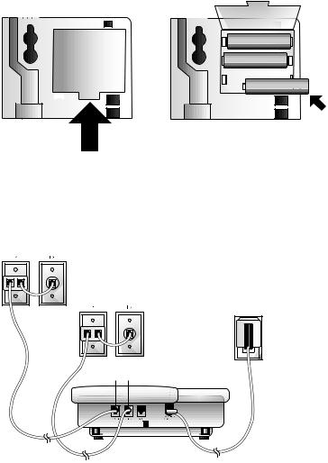
2 Connect the telephone line cords to the telephone.
NOTE: If the phone rings when you first connect the line cords, you need to set the phone’s intercom number. See “Assign Intercom Number” in the TELEPHONE FEATURE SETUP section of this manual.
•Four One-Line Jacks
Modular |
Telephone Jacks |
Lines 3 and 4 |
Modular |
Standard |
|
Telephone Jacks |
||
Electrical |
||
Lines 1 and 2 |
||
Outlet |
||
|
Telephone Jacks
Telephone |
Power Cord |
Line Cords |
|
4
INSTALLATION
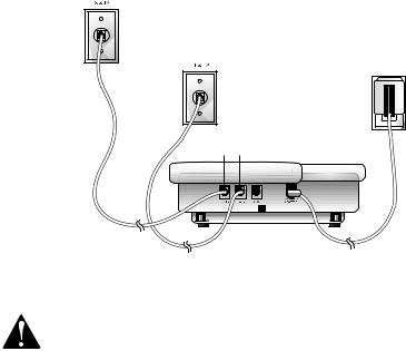
•Two Two-Line Jacks
Modular |
Telephone Jack |
Lines 3 and 4 |
Modular
Telephone Jack
Lines 1 and 2
Telephone Jacks
Standard |
Electrical |
Outlet |
Telephone |
Power Cord |
Line Cords |
|
3Connect the power adapter.
Use only the power adapter provided with this product. To obtain a replacement, call 1 800 222–3111.
Plug one end of the power adapter into the jack labeled ADAPTER on the back of the phone. Plug the other end into a standard electrical outlet.
4Connect the handset cord.
Plug one end of the coiled handset cord into the jack on the bottom of the phone. Plug the other end into the handset, and hang up.
5Check for dial tone.
Lift the handset and listen for a dial tone. If you cannot hear a dial tone, turn to IN CASE OF DIFFICULTY in this manual.
5
INSTALLATION
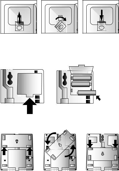
Wall Installation
1Reverse the handset tab.
Hold down the switchhook, then pull the tab out and rotate it 180 degrees. Release the tab so it settles into position.
2Install 3 AA batteries.
•Press in on the tabs and remove the telephone base.
•Press in on the tabs on the battery door, and remove it.
•Insert 3 AA batteries, and replace the battery door.
3Turn the base, as shown, and attach it to the bottom of the phone.
6
INSTALLATION
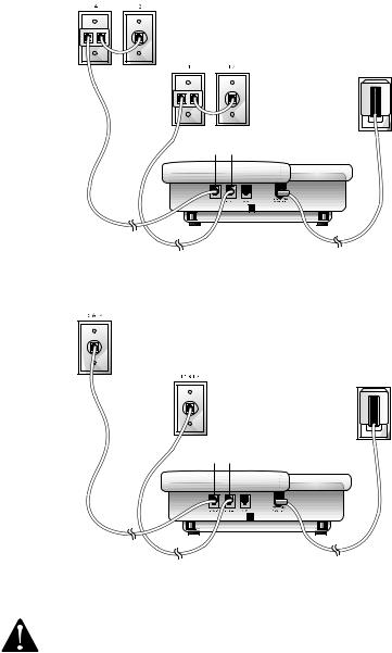
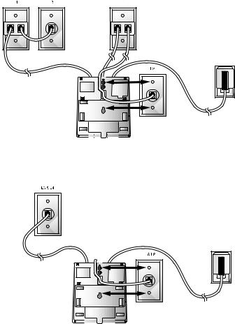
4Connect the telephone line cords to the telephone.
• Four One-Line Jacks
Modular
Telephone Jacks
Lines 3 and 4
Modular |
Standard |
|
Telephone Jacks |
||
Electrical |
||
Lines 1 and 2 |
||
Outlet |
||
|
Telephone Jacks
Telephone |
Power Cord |
Line Cords |
|
•Two Two-Line Jacks
Modular |
Telephone Jack |
Lines 3 and 4 |
Modular
Telephone Jack
Lines 1 and 2
Telephone Jacks
Standard |
Electrical |
Outlet |
Telephone |
Power Cord |
Line Cords |
|
5Connect the power adapter to the telephone.
Use only the power adapter provided with this product. To obtain a replacement, call 1 800 222–3111.
Plug one end of the power adapter into the jack labeled ADAPTER on the back of the phone.
7
INSTALLATION
6Mount the phone on the wall.
• Four One-Line Jacks
Modular
Telephone
Jacks Lines
3 and 4
Telephone
Line Cord
•Two Two-Line Jacks
Modular Telephone Jack Lines 3 and 4
Telephone
Line Cord
Modular
Telephone
Jack Line 1
Telephone
Line Cord
Modular
Telephone
Jack Line 2
Power Cord
Modular
Telephone Jack
Lines 1 and 2
Standard
Electrical
Outlet
Power Cord
Standard
Electrical
Outlet
NOTE: If you have three modular telephone jacks, mount the phone onto a jack without a wall-mounting adapter. If you have four modular telephone jacks, mount the phone onto a jack without a wall-mounting adapter.
8
 Loading...