


 Loading...
SABERTOOTH 990FX
Motherboard

E6674
Second Edition
May 2011
Copyright © 2011 ASUSTeK COMPUTER INC. All Rights Reserved.
No part of this manual, including the products and software described in it, may be reproduced, transmitted, transcribed, stored in a retrieval system, or translated into any language in any form or by any means, except documentation kept by the purchaser for backup purposes, without the express written permission of ASUSTeK COMPUTER INC. (“ASUS”).
Product warranty or service will not be extended if: (1) the product is repaired, modified or altered, unless such repair, modification of alteration is authorized in writing byASUS; or (2) the serial number of the product is defaced or missing.
ASUS PROVIDES THIS MANUAL “AS IS” WITHOUT WARRANTY OF ANY KIND, EITHER EXPRESS OR IMPLIED, INCLUDING BUT NOT LIMITED TO THE IMPLIED WARRANTIES OR CONDITIONS OF MERCHANTABILITY OR FITNESS FOR A PARTICULAR PURPOSE. IN NO EVENT SHALL ASUS, ITS DIRECTORS, OFFICERS, EMPLOYEES OR AGENTS BE LIABLE FOR ANY INDIRECT, SPECIAL, INCIDENTAL, OR CONSEQUENTIAL DAMAGES (INCLUDING DAMAGES FOR LOSS OF PROFITS, LOSS OF BUSINESS, LOSS OF USE OR DATA, INTERRUPTION OF BUSINESS AND THE LIKE), EVEN IF ASUS HAS BEEN ADVISED OF THE POSSIBILITY OF SUCH DAMAGES ARISING FROM ANY DEFECT OR ERROR IN THIS MANUAL OR PRODUCT.
SPECIFICATIONS AND INFORMATION CONTAINED IN THIS MANUAL ARE FURNISHED FOR INFORMATIONAL USE ONLY, AND ARE SUBJECT TO CHANGE AT ANY TIME WITHOUT NOTICE, AND SHOULD NOT BE CONSTRUED AS A COMMITMENT BY ASUS. ASUS ASSUMES NO RESPONSIBILITY OR LIABILITY FOR ANY ERRORS OR INACCURACIES THAT MAY APPEAR IN THIS MANUAL, INCLUDING THE PRODUCTS AND SOFTWARE DESCRIBED IN IT.
Products and corporate names appearing in this manual may or may not be registered trademarks or copyrights of their respective companies, and are used only for identification or explanation and to the owners’ benefit, without intent to infringe.
Offer to Provide Source Code of Certain Software
This product may contain copyrighted software that is licensed under the General Public License (“GPL”) and under the Lesser General Public License Version (“LGPL”). The GPL and LGPL licensed code in this product is distributed without any warranty. Copies of these licenses are included in this product.
You may obtain the complete corresponding source code (as defined in the GPL) for the GPL Software, and/or the complete corresponding source code of the LGPL Software (with the complete machinereadable “work that uses the Library”) for a period of three years after our last shipment of the product including the GPL Software and/or LGPL Software, which will be no earlier than December 1, 2011, either
(1) for free by downloading it from http://support.asus.com/download; or
(2) for the cost of reproduction and shipment, which is dependent on the preferred carrier and the location where you want to have it shipped to, by sending a request to:
ASUSTeK Computer Inc.
Legal Compliance Dept.
15 Li Te Rd.,
Beitou, Taipei 112
Taiwan
In your request please provide the name, model number and version, as stated in the About Box of the product for which you wish to obtain the corresponding source code and your contact details so that we can coordinate the terms and cost of shipment with you.
The source code will be distributed WITHOUT ANY WARRANTY and licensed under the same license as the corresponding binary/object code.
This offer is valid to anyone in receipt of this information.
ASUSTeK is eager to duly provide complete source code as required under various Free Open Source Software licenses. If however you encounter any problems in obtaining the full corresponding source code we would be much obliged if you give us a notification to the email address gpl@asus.com, stating the product and describing the problem (please do NOT send large attachments such as source code archives etc to this email address).
ii

Contents
Notices ....................................................................................................................... |
vii |
Safety information.................................................................................................... |
viii |
About this guide.......................................................................................................... |
ix |
SABERTOOTH 990FX specifications summary....................................................... |
xi |
Chapter 1: |
Product Introduction |
|
|
1.1 |
Welcome! |
..................................................................................................... |
1-1 |
1.2 |
Package contents....................................................................................... |
1-1 |
|
1.3 |
Special features.......................................................................................... |
1-2 |
|
|
1.3.1 ........................................................................ |
Product highlights |
1-2 |
|
1.3.2 ............................................. |
“Ultimate COOL!” Thermal Solution |
1-3 |
|
1.3.3 .................................................... |
“TUF ENGINE!” Power Design |
1-3 |
|
1.3.4 .................................................................................... |
ASUS DIY |
1-4 |
Chapter 2: |
Hardware information |
|
|
2.1 |
Before you proceed.................................................................................... |
2-1 |
|
2.2 |
Motherboard overview............................................................................... |
2-2 |
|
|
2.2.1 |
Motherboard layout...................................................................... |
2-2 |
|
2.2.2 |
Central Processing Unit (CPU).................................................... |
2-4 |
|
2.2.3 |
System memory........................................................................... |
2-5 |
|
2.2.4 |
Expansion slots.......................................................................... |
2-15 |
|
2.2.5 |
Jumper....................................................................................... |
2-18 |
|
2.2.6 |
Onboard switch.......................................................................... |
2-19 |
|
2.2.7 |
Onboard LEDs........................................................................... |
2-20 |
|
2.2.8 |
Internal connectors.................................................................... |
2-21 |
2.3 |
Building your computer system.............................................................. |
2-29 |
|
|
2.3.1 |
Additional tools and components to build a PC system............. |
2-29 |
|
2.3.2 |
CPU installation......................................................................... |
2-30 |
|
2.3.3 |
CPU heatsink and fan assembly installation.............................. |
2-31 |
|
2.3.5 |
Motherboard installation............................................................ |
2-34 |
|
2.3.6 |
ATX Power connection.............................................................. |
2-36 |
|
2.3.7 |
SATA device connection............................................................ |
2-37 |
|
2.3.8 |
Front I/O Connector................................................................... |
2-38 |
|
2.3.9 |
Expension Card installation....................................................... |
2-39 |
|
2.3.10 |
Rear panel connection............................................................... |
2-40 |
|
2.3.11 |
Audio I/O connections................................................................ |
2-41 |
2.4 |
Starting up for the first time.................................................................... |
2-44 |
|
2.5 |
Turning off the computer......................................................................... |
2-44 |
|
iii

Contents
Chapter 3: |
BIOS setup |
|
|
3.1 |
Knowing BIOS............................................................................................. |
3-1 |
|
3.2 |
BIOS setup program................................................................................... |
3-1 |
|
|
3.2.1 |
EZ Mode...................................................................................... |
3-2 |
|
3.2.2 |
Advanced Mode........................................................................... |
3-3 |
3.3 |
Main menu................................................................................................... |
3-5 |
|
3.4 |
Ai Tweaker menu........................................................................................ |
3-7 |
|
3.5 |
Advanced menu........................................................................................ |
3-14 |
|
|
3.5.1 |
CPU Configuration..................................................................... |
3-15 |
|
3.5.2 |
North Bridge Configuration........................................................ |
3-16 |
|
3.5.3 |
SATAConfiguration.................................................................... |
3-17 |
|
3.5.4 |
USB Configuration..................................................................... |
3-19 |
|
3.5.5 |
CPU Core On/Off Fuction.......................................................... |
3-20 |
|
3.5.6 |
Onboard Devices Configuration................................................. |
3-21 |
|
3.5.7 |
APM........................................................................................... |
3-23 |
3.6 |
Monitor menu............................................................................................ |
3-24 |
|
3.7 |
Boot menu................................................................................................. |
3-27 |
|
3.8 |
Tools menu................................................................................................ |
3-28 |
|
3.9 |
Exit menu................................................................................................... |
3-30 |
|
3.10 |
Updating BIOS.......................................................................................... |
3-31 |
|
|
3.10.1 |
ASUS Update utility................................................................... |
3-31 |
|
3.10.2 |
ASUS EZ Flash 2 utility............................................................. |
3-34 |
|
3.10.3 |
ASUS BIOS Updater.................................................................. |
3-36 |
Chapter 4: |
Software support |
|
|
4.1 |
Installing an operating system.................................................................. |
4-1 |
|
4.2 |
Support DVD information........................................................................... |
4-1 |
|
|
4.2.1 |
Running the support DVD............................................................ |
4-1 |
|
4.2.2 |
Obtaining the software manuals.................................................. |
4-2 |
4.3 |
Software information.................................................................................. |
4-3 |
|
|
4.3.1 |
AI Suite II..................................................................................... |
4-3 |
|
4.3.2 |
ASUS Thermal Radar.................................................................. |
4-8 |
|
4.3.3 |
Tool............................................................................................ |
4-12 |
|
4.3.4 |
Monitor....................................................................................... |
4-21 |
|
4.3.5 |
Update....................................................................................... |
4-22 |
|
4.3.6 |
System Information.................................................................... |
4-27 |
|
4.3.7 |
Audio configurations.................................................................. |
4-28 |
4.4 |
RAID configurations................................................................................. |
4-29 |
|
|
4.4.1 |
RAID definitions......................................................................... |
4-29 |
iv

Contents
|
4.4.2 |
Installing Serial ATA hard disks.................................................. |
4-30 |
|
4.4.3 |
Setting the RAID item in BIOS................................................... |
4-30 |
|
4.4.4 |
AMD® Option ROM Utility.......................................................... |
4-31 |
4.5 |
Creating a RAID driver disk..................................................................... |
4-34 |
|
|
4.5.1 |
Creating a RAID driver disk without entering the OS................. |
4-34 |
|
4.5.2 |
Creating a RAID driver disk in Windows®.................................. |
4-34 |
|
4.5.3 |
Installing the RAID driver during Windows® OS installation....... |
4-35 |
|
4.5.4 |
Using a USB floppy disk drive................................................... |
4-36 |
Chapter 5: |
Multiple GPU technology support |
|
|
5.1 |
ATI® CrossFireX™ technology................................................................... |
5-1 |
|
|
5.1.1 |
Requirements.............................................................................. |
5-1 |
|
5.1.2 |
Before you begin.......................................................................... |
5-1 |
|
5.1.3 |
Installing two CrossFireX™ graphics cards................................. |
5-2 |
|
5.1.4 |
Installing the device drivers......................................................... |
5-3 |
|
5.1.5 |
Enabling the ATI® CrossFireX™ technology................................ |
5-3 |
5.2 |
NVIDIA® SLI™ technology........................................................................ |
5-4 |
|
|
5.2.1 |
Requirements.............................................................................. |
5-4 |
|
5.2.2 |
Installing two SLI-ready graphics cards....................................... |
5-4 |
|
5.2.3 |
Installing the device drivers......................................................... |
5-5 |
|
5.2.4 |
Enabling the NVIDIA® SLI™ technology...................................... |
5-5 |
Notices
Federal Communications Commission Statement
This device complies with Part 15 of the FCC Rules. Operation is subject to the following two conditions:
•This device may not cause harmful interference, and
•This device must accept any interference received including interference that may cause undesired operation.
This equipment has been tested and found to comply with the limits for a Class B digital device, pursuant to Part 15 of the FCC Rules. These limits are designed to provide reasonable protection against harmful interference in a residential installation. This equipment generates, uses and can radiate radio frequency energy and, if not installed and used in accordance with manufacturer’s instructions, may cause harmful interference to radio communications. However, there is no guarantee that interference will not occur in a particular installation. If this equipment does cause harmful interference to radio or
television reception, which can be determined by turning the equipment off and on, the user is encouraged to try to correct the interference by one or more of the following measures:
•Reorient or relocate the receiving antenna.
•Increase the separation between the equipment and receiver.
•Connect the equipment to an outlet on a circuit different from that to which the receiver is connected.
•Consult the dealer or an experienced radio/TV technician for help.
The use of shielded cables for connection of the monitor to the graphics card is required to assure compliance with FCC regulations. Changes or modifications to this unit not expressly approved by the party responsible for compliance could void the user’s authority to operate this equipment.
Canadian Department of Communications Statement
This digital apparatus does not exceed the Class B limits for radio noise emissions from digital apparatus set out in the Radio Interference Regulations of the Canadian Department of Communications.
This class B digital apparatus complies with Canadian ICES-003.
REACH
Complying with the REACH (Registration, Evaluation, Authorisation, and Restriction of Chemicals) regulatory framework, we published the chemical substances in our products at ASUS REACH website at http://csr.asus.com/english/REACH.htm.
DO NOT throw the motherboard in municipal waste. This product has been designed to enable proper reuse of parts and recycling. This symbol of the crossed out wheeled bin indicates that the product (electrical and electronic equipment) should not be placed in municipal waste. Check local regulations for disposal of electronic products.
DO NOT throw the mercury-containing button cell battery in municipal waste. This symbol of the crossed out wheeled bin indicates that the battery should not be placed in municipal waste.
vi

Safety information
Electrical safety
•To prevent electrical shock hazard, disconnect the power cable from the electrical outlet before relocating the system.
•When adding or removing devices to or from the system, ensure that the power cables for the devices are unplugged before the signal cables are connected. If possible, disconnect all power cables from the existing system before you add a device.
•Before connecting or removing signal cables from the motherboard, ensure that all power cables are unplugged.
•Seek professional assistance before using an adapter or extension cord. These devices could interrupt the grounding circuit.
•Ensure that your power supply is set to the correct voltage in your area. If you are not sure about the voltage of the electrical outlet you are using, contact your local power company.
•If the power supply is broken, do not try to fix it by yourself. Contact a qualified service technician or your retailer.
Operation safety
•Before installing the motherboard and adding devices on it, carefully read all the manuals that came with the package.
•Before using the product, ensure all cables are correctly connected and the power cables are not damaged. If you detect any damage, contact your dealer immediately.
•To avoid short circuits, keep paper clips, screws, and staples away from connectors, slots, sockets and circuitry.
•Avoid dust, humidity, and temperature extremes. Do not place the product in any area where it may become wet.
•Place the product on a stable surface.
•If you encounter technical problems with the product, contact a qualified service technician or your retailer.
vii

About this guide
This user guide contains the information you need when installing and configuring the motherboard.
How this guide is organized
This guide contains the following parts:
•Chapter 1: Product introduction
This chapter describes the features of the motherboard and the new technology it supports.
•Chapter 2: Hardware information
This chapter lists the hardware setup procedures that you have to perform when installing system components. It includes description of the switches, jumpers, and connectors on the motherboard.
•Chapter 3: BIOS setup
This chapter tells how to change system settings through the BIOS Setup menus. Detailed descriptions of the BIOS parameters are also provided.
•Chapter 4: Software support
This chapter describes the contents of the support DVD that comes with the motherboard package and the software.
•Chapter 5: Multiple GPU technology support
This chapter describes how to install and configure multipleATI® CrossFireX™ and NVIDIA® SLI™ graphics cards.
Where to find more information
Refer to the following sources for additional information and for product and software updates.
1.ASUS websites
The ASUS website provides updated information on ASUS hardware and software products. Refer to the ASUS contact information.
2.Optional documentation
Your product package may include optional documentation, such as warranty flyers, that may have been added by your dealer. These documents are not part of the standard package.
viii

Conventions used in this guide
To ensure that you perform certain tasks properly, take note of the following symbols used throughout this manual.
DANGER/WARNING: Information to prevent injury to yourself when trying to complete a task.
CAUTION: Information to prevent damage to the components when trying to complete a task.
IMPORTANT: Instructions that you MUST follow to complete a task.
NOTE: Tips and additional information to help you complete a task.
Typography
Bold text |
Indicates a menu or an item to select. |
Italics |
Used to emphasize a word or a phrase. |
<Key> |
Keys enclosed in the less-than and greater-than sign means |
|
that you must press the enclosed key. |
|
Example: <Enter> means that you must press the Enter or |
|
Return key. |
<Key1> + <Key2> + <Key3> |
If you must press two or more keys simultaneously, the key |
|
names are linked with a plus sign (+). |
|
Example: <Ctrl> + <Alt> + <Del> |
ix
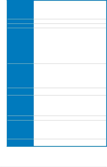
SABERTOOTH 990FX specifications summary
CPU
Chipset
System Bus
Memory
Expansion Slots
Multi-GPU Technology
Storage
LAN
High Definition Audio
IEEE 1394
AMD® socket AM3+ for AMD® FX Series CPU up to 8-core Compatible with AMD® socket AM3 for AMD® Phenom™ II/ Athlon™ II/Sempron™ 100 Series Processors
Supports 32nm CPU
AMD® Cool 'n' Quiet™ Technology
AMD® 140W CPU Support
AMD® 990FX/SB950
Up to 5.2 GT/s HyperTransport™ 3.0
*4 x DIMM, Max. 32GB, DDR3 1866/1600/1333/1066 MHz, ECC, Non-
ECC and un-buffered memory
Dual channel memory architecture
*Refer to www.asus.com or user manual for the Memory QVL (Qualified
Vendors Lists) of AM3+ / AM3 CPU
**Due to OS limitation, when installing total memory of 4GB capacity or more, Windows® 32-bit operation system may only recognize less than 3GB. Hence, a total installed memory of less than 3GB is recommended.
***Due to CPU spec, AMD 100 Series CPUs support up to DDR3
1066MHz. WithASUS design, this mptherboard can support up to DDR3 1333MHz.
3 x PCI Express 2.0 x16 slots (single @ x16, dual @ x16 / x16, triple @ x16 / x8 / x8 mode)*
1 x PCI Express 2.0 x16 slot (Black @ x4)
1 x PCI Express 2.0 x1 slot
1 x PCI slot
*In dual VGA card mode, ensure to install the VGA cards to PCIex16_1 and PCIex16_3 for better performance. Refer to “2.5 Expansion slots” for details.
Support NVIDIA® Quad-GPU SLI™ and ATI® Quad-GPU CrossFireX™
Technology
AMD® SB950 Chipset:
- 6 x SATA 6Gb/s ports with RAID 0, 1, 5, 10 support
2 x JMicron® JMB362 SATA controllers:
- 2 x SATA 3Gb/s ports
- 1 x Power eSATA 3Gb/s port (green) - 1 x eSATA 3Gb/s port (red)
Realtek® 8111E Gigabit LAN controller
Realtek® ALC892 8-channel High DefinitionAudio CODEC - Absolute Pitch 192KHz/24bit True BD Lossless Sound
- BD Audio Layer Content Protection
- Supports Jack-Detection, Multi-streaming, Front
Panel Jack-Retasking
- Optical S/PDIF out port at back I/O
VIA® VT6308P controller supports 2 x IEEE 1394a ports (1 port at midboard; 1 port at back panel)
*Refer to Chapter 2 for slot configurations.
(continued on the next page)
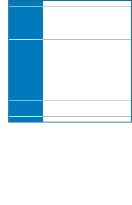
SABERTOOTH 990FX specifications summary
USB
Exclusive TUF Features
Other Special Features
BIOS Features
2 x ASMedia® USB 3.0 controllers
- 2 x USB 3.0 ports at mid-board for front panel support - 2 x USB 3.0 ports at back panel (blue)
AMD® SB950 chipset
- 14 x USB 2.0 ports (4 ports at mid-board, 10 ports at back panel
Ultimate COOL! Thermal Solution
- TUF CeraM!X Heatsink Coating Tech.
- TUF Thermal Radar
“TUF ENGINE!” Power Design
- 8+2 Digital phase Power Design
- TUF Components (Alloy choke, Cap. & MOSFET; certified |
|
by military-standard) |
|
- |
ASUS DIGI+VRM Utility |
- E. S. P. : Efficient Switching Power Disign |
|
“Safe & Stable!” Guardian Angel |
|
- |
ESD Guards |
- |
MemOK! |
- |
Anti Surge |
Front Panel USB 3.0 Support
ASUS UEFI BIOS EZ Mode featuring friendly graphics user interface
AI Suite II
ASUS Q-Connector
ASUS Q-Shield
ASUS Q-LED (CPU, DRAM, VGA, Boot Device LED)
ASUS Q-Slot
ASUS Q-DIMM
ASUS O.C. Profile
ASUS EZ Flash 2
ASUS MyLogo 2
Multi-language BIOS
32 Mb Flash ROM, UEFI BIOS, PnP, DMI2.0, WfM2.0, SM BIOS 2.5, ACPI 2.0a, Multi-language BIOS, ASUS EZ Flash 2
(continued on the next page)
xi
SABERTOOTH 990FX specifications summary
Manageability
Back Panel I/O Ports
Internal I/O Connectors
Software
Form Factor
WfM 2.0, DMI 2.0, WOL by PME, WOR by PME, PXE
1 x PS/2 Keyboard/Mouse combo port
1 x Optical S/PDIF Output port
1 x Power eSATA 3Gb/s port (green)
1 x eSATA 3Gb/s port (red)
1 x IEEE1394a port
1 x LAN (RJ45) port
2 x USB 3.0/2.0 ports (blue)
10 x USB 2.0/1.1 ports
8-channel Audio I/O ports
1 x USB 3.0/2.0 connector supports additional 2 USB 3.0/2.0 ports
(19-pin; moss green)
2 x USB 2.0/1.1 connectors support additional 4 USB 2.0/1.1 ports 6 x SATA 6Gb/s connectors (brown)
2 x SATA 3Gb/s connectors (black)
1 x CPU Fan connector (4-pin)
4 x Chassis Fan connectors (3 x 4-pin; 1 x 3-pin)
1 x CPU Opt fan connector (4-pin)
1 x IEEE1394a connector Front panel audio connector 1 x COM connector
1 x S/PDIF Out header
24-pin EATX Power connector
8-pin EATX 12V Power connector System Panel (Q-Connector)
1 x MemOK! button
1 x Clear CMOS jumper
Drivers
Anti-virus software (OEM version)
ASUS Update
ASUS Utilities
ATX Form Factor, 12”x 9.6” (30.5cm x 24.4cm)
*Specifications are subject to change without notice.
xii
Chapter 1
1.1Welcome!
Thank you for buying an ASUS® SABERTOOTH 990FX motherboard!
The motherboard delivers a host of new features and latest technologies, making it another standout in the long line of ASUS quality motherboards!
Before you start installing the motherboard, and hardware devices on it, check the items in your package with the list below.
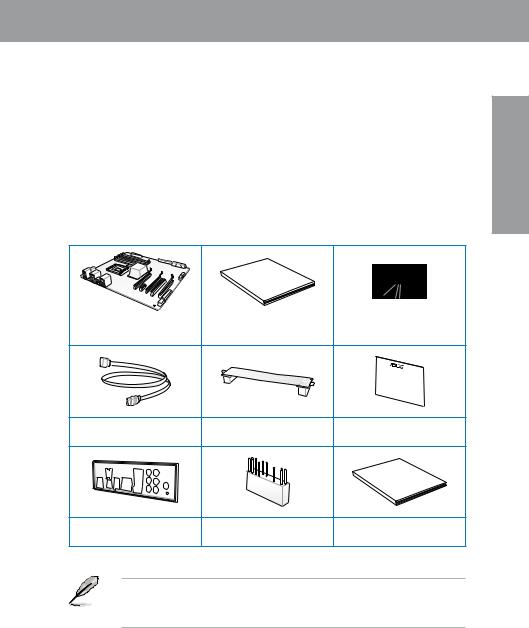
1.2Package contents
Check your motherboard package for the following items.
Manual
User
ASUS SABERTOOTH 990FX |
User guide |
Support DVD |
|
motherboard |
|||
|
|
4 x Serial ATA 6.0 Gb/s cables |
1 x ASUS SLI™ bridge |
1 x TUF Certification card |
||
connector |
||||
|
|
|
||
|
|
|
warranty |
|
|
|
-year |
||
|
|
Five |
|
|
1 x ASUS Q-Shield |
1 x 2-in-1 ASUS Q-Connector kit |
1 x TUF Five-year warranty |
||
|
manual |
|||
|
|
|
||
•If any of the above items is damaged or missing, contact your retailer.
•The illustrated items above are for reference only.Actual product specifications may vary with different models.
Chapter 1
ASUS SABERTOOTH 990FX |
1-1 |

1 Chapter
1.3Special features
1.3.1Product highlights
The Ultimate Force 

TUF /tΛf/, stands for The Ultimate Force.
The TUF series delivers a “tough” image. With the unique design & high quality components (military-standard), TUF series is born for pursuing the preeminent stability, all-round compatibility, and extreme durability
FX™/Phenom™ II/Athlon™ II/ Sempron™ 100 Series Processors (AM3+ / AM3 CPU)
This motherboard supports latest AMD® Socket AM3+ multi-core processors with up to 8-core native CPU cores and delivers better overclocking capabilities with less power consumption. It features AMD Turbo CORE Technology 2.0 and accelerates data transfer rate up to 5200MT/s via HyperTransport™ 3.0 based system bus. This motherboard also supports AMD® CPUs in the new 32nm manufacturing process.
AMD 990FX Chipset
AMD 990FX Chipset is designed to support up to 5.2GT/s HyperTransport™ 3.0 (HT 3.0) interface speed and dual PCI Express™ 2.0 x16 graphics. It is optimized withAMD latest
AM3+ and multi-core CPUs to provide excellent system performance and overclocking capabilities.
Quad-GPU SLI and Quad-GPU CrossFireX™ support!
Flexible Multi-GPU Solutions, Your Weapon of Choice!
SABERTOOTH 990FX brings multi-GPU configurations through both SLI™ and CrossFireX. This motherboard features the powerful AMD® 990FX chipset, optimizing PCIe allocation in multiple GPU setups. Expect a brand new gaming sensation like you’ve never experienced before!
PCIe 2.0
Double Speed; Double Bandwidth
This motherboard supports the latest PCIe 2.0 devices for double speed and bandwidth which enhances system performance.
Front Panel USB 3.0 Support
Convenient USB 3.0 Front Panel Compatibility
ASUS provides standardized USB 3.0 front panel support, compatible with any chassis.
Enjoy faster throughput of USB 3.0 without relegating cables or devices to the hard-to-reach rear I/O.
Complete USB 3.0 Solution
Double USB access, double convenience
ASUS facilitates strategic USB 3.0 accessibility for both the front and rear panel - 4 USB 3.0 ports in total. Experience the latest plug & play connectivity at speeds up to 10 times faster than USB 2.0. The SABERTOOTH 990FX affords greater convenience to high speed connectivity.
1-2 |
Chapter 1: Product Introduction |

1.3.2“Ultimate COOL!” Thermal Solution
TUF CeraM!X - Heatsink Coating Tech.
Larger area for heat dissipation with the revolutionary ceramics-coating technology
Innovative ceramics actively conducts heat away from the system. It replaces traditional anti-oxidant to dissipate heat better with its microscopic irregular surface and enlarged area. Better cooling leads to overall improvement in system stability.
Do Not uninstall the heatsink module by youself. Doing so may bend the tubing and affect the heat dissipation performance.
TUF Thermal Radar
Real Time Temp Detection and Heat Removal
The TUF Thermal Radar monitors temps in critical parts of the motherboard in real time, automatically adjusting fan speeds to make sure the system maintains high stability without overheating. It consists of multiple sensors for various components on the motherboard, giving users the ability to monitor each one individually. The Thermal Radar automatically calculates ideal fan speeds based on different parameters selected by users for each component, keeping everything cooler and longer lasting.
1.3.3“TUF ENGINE!” Power Design
DIGI+ VRM
Herald the Arrival of a New Digital Power Design Era
The new ASUS DIGI+ VRM design upgrades motherboard power delivery to a digital standard. The 8+2 digital architecture provides the highest power efficiency, generating less heat to enhance longer component lifespan and ensure minimal powerloss. With ASUS DIGI+ VRM, users can easily adjust power phase performance, enabling new PWM voltage and frequency modulation controls. Digital 8+2 power phase design also expands the modulation spectrum for improved stability and lower VRM switching noise by dynamically detecting system load, empowering users with superior flexibility and perfect precision to ensure optimized performance, extreme system stability, and greater power efficiency.
E.S.P. Efficient Switching Power Design
Optimal power efficiency for key components
Exclusively for this motherboard, the switching power design is provided not only for the CPU and memory, but also for other key components such as graphics cards, LAN and USB 3.0.
E.S.P. dramatically improves system efficiency and reduces heat generation.
Chapter 1
ASUS SABERTOOTH 990FX |
1-3 |

1 Chapter
TUF Components (Alloy Choke, Cap. & MOSFET; Certified by Militarystandard)
Certified for Tough Duty
Get rugged performance even in the most challenging conditions with robust TUF chokes, solid capacitors, and MOSFETs--certified through third-party, military-grade testing. TUF
Chokes, also known as the “Alloy Choke”, is a made of a compound of various types of metal instead standard iron, enables the support of up to a massive 40A of rated current, 25% higher than conventional component. Furthermore, the single piece packaing also elimates the emission of virbation noise, delivering superb charactoristics as well as durability under extreme conditions.
ESD Guards
Unique protection of motherboard components from unexpected electrostatic discharges (ESD)
Electrostatic discharge (ESD) can happen suddenly and its damaging effects is often underestimated. Exclusive ASUS anti-static chip, a protective circuit design, and the I/O shield provides four times better protection to extend component lifespan.
Any Memory is A-OK!
MemOK! quickly ensures memory boot compatibility. This remarkable memory rescue tool requires a mere push of a button to patch memory issues. MemOK! determines failsafe settings and dramatically improves system boot success. Get your system up and running in no time!
1.3.4ASUS DIY
UEFI BIOS (EZ Mode)
Flexible & Easy BIOS Interface
ASUS brand new UEFI BIOS offers a user-friendly interface that goes beyond traditional keyboard only BIOS, to enable more flexible and convenient mouse controls. Users can easily navigate the new UEFI BIOS with the same smoothness as their operating system.
The exclusive EZ Mode displays frequently-accessed setup info, while the Advanced Mode is for experienced performance enthusiasts that demand far more intricate system settings.
AI Suite II
One-stop Access to Innovative ASUS Features
With its user-friendly interface, ASUS AI Suite II consolidates all the exclusive ASUS features into one simple to use software package. It allows you to supervise energy management, fan speed control, voltage and sensor readings. This all-in-one software offers diverse and ease to use functions, with no need to switch back and forth between different utilities.
1-4 |
Chapter 1: Product Introduction |

ASUS Q-Design
DIY quickly, DIY easily!
ASUS Q-Design enhances your DIY experience. All of Q-LED, Q-Slot, and Q-DIMM design speed up and simplify the DIY process!
Q-Shield
Easy and Comfortable Installations
The specially designedASUS Q-Shield does without the usual ""fingers"" - making it convenient and easy to install. With better electric conductivity, it ideally protects your motherboard against static electricity and shields it against Electronic Magnetic Interference (EMI).
ASUS Q-Connector
Make connection quick and accurate!
The ASUS Q-Connector allows you to connect or disconnect chassis front panel cables in one easy step with one complete module. This unique adapter eliminates the trouble of plugging in one cable at a time, making connection quick and accurate.
EZ Flash2
Simply update BIOS from a USB flash disk before entering the OS
EZ Flash 2 is a user-friendly BIOS update utility. Simply launch this tool and update BIOS from a USB flash disk before entering the OS. You can update your BIOS only in a few clicks without preparing an additional floppy diskette or using an OS-based flash utility.
O.C. Profile
Conveniently store or load multiple BIOS settings
Freely share and distribute favorite overclocking settings The motherboard features the
ASUS O.C. Profile that allows users to conveniently store or load multiple BIOS settings. The BIOS settings can be stored in the CMOS or a separate file, giving users freedom to share and distribute their favorite overclocking settings.
8 Channel Audio Codec
The onboard 8-channel HD audio (High DefinitionAudio, previously codenamedAzalia) CODEC enables high-qualityAbsolute Pitch 192khz/24bit audio output, true BD lossless sound, jack-sensing feature, retasking functions and multi-streaming technology.
MyLogo2
Personalize your system with customizable boot logo
The ASUS MyLogo 2 is the new feature present in the motherboard that allows you to personalize and add style to your system with customizable and animated boot logos.
Chapter 1
ASUS SABERTOOTH 990FX |
1-5 |

1 Chapter
Power eSATA on the Go
The motherboard supports hard drives based on the Serial ATA (SATA) 3Gb/s storage specification, delivering enhanced scalability and doubling the bus bandwidth for high-speed data retrieval and saves.The Power eSATA solution combines the eSATA connector and power source together, allowing users to use external SATA devices without the need of additional power source*. The external SATA port located at the back I/O provides smart setup and hot-plug functions. Easily backup photos, videos and other entertainment contents on external devices. *Power eSATA requires a specially designed signal cable to provide 5V power for the external SATA device. The cable is purchased separately.
IEEE 1394a interface
IEEE 1394a interface provides high speed digital interface for audio/video appliances such as digital television, digital video camcorders, storage peripherals & other PC portable devices.
ErP Ready
The motherboard is European Union’s Energy-related Products (ErP) ready, and ErP requires products to meet certain energy efficiency requirements in regards to energy consumptions. This is in line withASUS vision of creating environment-friendly and energy-efficient products through product design and innovation to reduce carbon footprint of the product and thus mitigate environmental impacts.
1-6 |
Chapter 1: Product Introduction |

Chapter 2
2.1Before you proceed
Take note of the following precautions before you install motherboard components or change any motherboard settings.
• Unplug the power cord from the wall socket before touching any component.
• Before handling components, use a grounded wrist strap or touch a safely grounded object or a metal object, such as the power supply case, to avoid damaging them due to static electricity.
•Hold components by the edges to avoid touching the ICs on them.
•Whenever you uninstall any component, place it on a grounded antistatic pad or in the bag that came with the component.
•Before you install or remove any component, ensure that the ATX power supply is switched off or the power cord is detached from the power supply. Failure to do so may cause severe damage to the motherboard, peripherals, or components.
ASUS SABERTOOTH 990FX |
2-1 |

2.2Motherboard overview
2.2.1Motherboard layout
2 Chapter
Refer to 2.2.8 Internal connectors and 2.3.10 Rear panel connection for more information about rear panel connectors and internal connectors.
2-2 |
Chapter 2: Hardware information |
Layout contents
Connectors/Jumpers/Slots |
Page |
|
1. |
ATX power connectors (24-pin EATXPWR, 8-pin EATX12V) |
2-21 |
2. |
AM3+ CPU socket |
2-4 |
3. |
CPU and chassis fan connectors |
2-20 |
|
(4-pin CPU_FAN, CPU_OPT FAN, CHA_FAN1~3, 3-pin |
|
|
CHA_FAN4) |
|
4. |
DDR3 DIMM slots |
2-5 |
5. |
MemOK! switch |
2-14 |
6. |
USB 3.0 connector (20-1 pin USB3_34) |
2-18 |
7. |
JMicron® Serial ATA 3.0 Gb/s connectors (7-pin SATA3G_E1/E2 |
2-17 |
|
[black]) |
|
|
|
|
8. |
AMD® Serial ATA 6.0 Gb/s connectors (7-pin SATA6G_1-6 |
2-16 |
|
[brown]) |
|
|
|
|
9. |
System panel connector (20-8 pin PANEL) |
2-23 |
10. |
Serial port connector (10-1 pin COM1) |
2-17 |
11. |
Clear RTC RAM (3-pin CLRTC) |
2-13 |
12. |
USB 2.0 connectors (10-1 pin USB1112, USB1314) |
2-18 |
13. |
Standby power LED (SB_PWR) |
2-15 |
14. |
IEEE 1394a port connector (10-1 pin IE1394_2) |
2-19 |
15. |
Front panel audio connector (10-1 pin AAFP) |
2-21 |
16. |
Digital audio connector (4-1 pin SPDIF_OUT) |
2-19 |
Chapter 2
ASUS SABERTOOTH 990FX |
2-3 |
2 Chapter
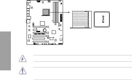
2.2.2Central Processing Unit (CPU)
The motherboard comes with an AM3+ socket designed for AMD® FX Series CPU up to 8-core, also compatible with AMD® socket AM3 for AMD® Phenom™ II/Athlon™ II/ Sempron™ 100 Series Processors.


 +
+
Ensure that all power cables are unplugged before installing the CPU.
The AM3+ socket has a different pinout designe, ensure that you use a CPU designed for theAM3+/AM3 socket. The CPU fits in only one correct orientation. DO NOT force the CPU into the socket to prevent bending the connectors on the socket and damaging the CPU!
2-4 |
Chapter 2: Hardware information |
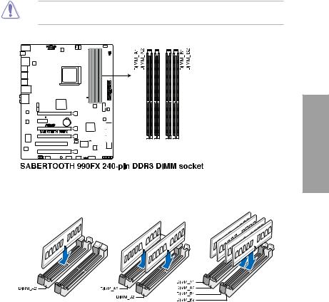
2.2.3System memory
The motherboard comes with four Double Data Rate 3 (DDR3) Dual Inline Memory Modules (DIMM) slots.
A DDR3 module is notched differently from a DDR or DDR2 module. DO NOT install a DDR or DDR2 memory module to the DDR3 slot.
Chapter 2
Recommended memory configurations
ASUS SABERTOOTH 990FX |
2-5 |

Memory configurations
You may install 1GB, 2GB and 4GB unbuffered and non ECC DDR3 DIMMs into the DIMM sockets.
2 Chapter
•You may install varying memory sizes in ChannelAand Channel B. The system maps the total size of the lower-sized channel for the dual-channel configuration.Any excess memory from the higher-sized channel is then mapped for single-channel operation.
•Due to CPU behavior, DDR3 1800 MHz memory module will run at DDR3 1600 MHz frequency as default.
•Always install DIMMs with the same CAS latency. For optimum compatibility, we recommend that you obtain memory modules from the same vendor.
•Due to the memory address limitation on 32-bit Windows OS, when you install 4GB or more memory on the motherboard, the actual usable memory for the OS can be about 3GB or less. For effective use of memory, we recommend that you do any of the following:
-Use a maximum of 3GB system memory if you are using a 32-bit Windows OS.
-Install a 64-bit Windows OS when you want to install 4GB or more on the motherboard.
For more details, refer to the Microsoft® support site at http://support.microsoft.com/kb/929605/en-us.
•This motherboard does not support DIMMs made up of 512Mb (64MB) chips or less (Memory chip capacity counts in Megabit, 8 Megabit/Mb = 1 Megabyte/MB).
•The default memory operation frequency is dependent on its Serial Presence Detect (SPD), which is the standard way of accessing information from a memory module. Under the default state, some memory modules for overclocking may operate at a lower frequency than the vendor-marked value. To operate at the vendor-marked
or at a higher frequency, refer to section 3.4 Ai Tweaker menu for manual memory frequency adjustment.
•For system stability, use a more efficient memory cooling system to support a full memory load (4 DIMMs) or overclocking condition.
2-6 |
Chapter 2: Hardware information |

SABERTOOTH 990FX Motherboard Qualified Vendors Lists (QVL)
AM3 DDR3 1066 MHz capability
Vendors |
Part No. |
Size |
SS/ |
Chip Brand |
Chip NO. |
Timing |
Voltage |
DIMM socket support |
|||
|
|
|
DS |
|
|
|
|
(Optional) |
|
|
|
|
|
|
|
|
|
|
|
1 DIMM |
2 DIMM |
4 DIMM |
|
Crucial |
CT12864BA1067.8FF |
1GB |
SS |
MICRON |
D9KPT |
7 |
- |
• |
• |
• |
|
Crucial |
CT12864BA1067.8SFD |
1GB |
SS |
MICRON |
D9JNL |
7 |
- |
• |
• |
• |
|
Crucial |
CT12872BA1067.9FF |
1GB |
SS |
MICRON |
D9KPT(ECC) |
7 |
- |
• |
• |
• |
|
Crucial |
CT25664BA1067.16FF |
2GB |
DS |
MICRON |
D9KPT |
7 |
- |
• |
• |
• |
|
Crucial |
CT25664BA1067.16SFD |
2GB |
DS |
MICRON |
D9JNL |
7 |
- |
• |
• |
• |
|
Crucial |
CT25672BA1067.18FF |
2GB |
DS |
MICRON |
D9KPT(ECC) |
7 |
- |
• |
• |
• |
|
ELPIDA |
EBJ10UE8BAW0-AE-E |
1GB |
SS |
ELPIDA |
J1108BABG-DJ-E |
7 |
- |
• |
• |
• |
|
ELPIDA |
EBJ10UE8EDF0-AE-F |
1GB |
SS |
ELPIDA |
J1108EDSE-DJ-F |
- |
- |
• |
• |
|
|
ELPIDA |
EBJ21UE8BAW0-AE-E |
2GB |
DS |
ELPIDA |
J1108BABG-DJ-E |
7 |
- |
• |
• |
• |
|
ELPIDA |
EBJ21UE8EDF0-AE-F |
2GB |
DS |
ELPIDA |
J1108EDSE-DJ-F |
- |
- |
• |
• |
• |
|
GEIL |
GG34GB1066C8DC |
4GB |
DS |
GEIL |
GL1L128M88BA115FW |
8-8-8-20 |
1.3 |
• |
|
• |
|
|
|
( 2x 2GB ) |
|
|
|
|
|
|
|
|
|
Hynix |
HMT112U6AFP8C-G7N0 |
1GB |
SS |
HYNIX |
H5TQ1G83AFPG7C |
7 |
- |
• |
• |
• |
|
Hynix |
HYMT112U64ZNF8-G7 |
1GB |
SS |
HYNIX |
HY5TQ1G831ZNFP-G7 |
7 |
- |
• |
• |
|
|
Hynix |
HMT125U6AFP8C-G7N0 |
2GB |
DS |
HYNIX |
H5TQ1G83AFPG7C |
7 |
- |
• |
• |
• |
|
Hynix |
HYMT125U64ZNF8-G7 |
2GB |
DS |
HYNIX |
HY5TQ1G831ZNFP-G7 |
7 |
- |
• |
• |
• |
|
Kingston |
KVR1066D3N7/1G |
1GB |
SS |
Kingston |
D1288JPNDPLD9U |
7 |
1.5 |
• |
• |
• |
|
Kingston |
KVR1066D3N7/2G |
2GB |
DS |
Elpida |
J1108BDSE-DJ-F |
7 |
1.5 |
• |
• |
• |
|
KINGSTON |
KVR1066D3N7K2/4G |
4GB |
DS |
KINGSTON |
D1288JELDNGD9U |
- |
1.5 |
• |
• |
• |
|
|
|
( 2x 2GB ) |
|
|
|
|
|
|
|
|
|
MICRON |
MT8JTF12864AZ-1G1F1 |
1GB |
SS |
MICRON |
8ZF22 D9KPV |
7 |
- |
• |
• |
• |
|
MICRON |
MT8JTF12864AZ-1G1F1 |
1GB |
SS |
MICRON |
D9KPT |
7 |
- |
• |
• |
• |
|
MICRON |
MT9JSF12872AZ-1G1F1 |
1GB |
SS |
MICRON |
D9KPT(ECC) |
7 |
- |
• |
• |
• |
|
MICRON |
MT16JTF25664AZ- |
2GB |
DS |
MICRON |
8ZF22 D9KPV |
7 |
- |
• |
• |
• |
|
|
1G1F1 |
|
|
|
|
|
|
|
|
|
|
MICRON |
MT16JTF25664AZ- |
2GB |
DS |
MICRON |
D9KPT |
7 |
- |
• |
• |
• |
|
|
1G1F1 |
|
|
|
|
|
|
|
|
|
|
MICRON |
MT18JSF25672AZ- |
2GB |
DS |
MICRON |
D9KPT(ECC) |
7 |
- |
• |
• |
• |
|
|
1G1F1 |
|
|
|
|
|
|
|
|
|
|
SAMSUNG |
M378B5273BH1-CF8 |
4GB |
DS |
SAMSUNG |
K4B2G0846B-HCF8 |
8 |
1.5 |
• |
• |
• |
|
Elixir |
M2Y2G64CB8HC5N-BE |
2GB |
DS |
Elixir |
N2CB1G80CN-BE |
- |
- |
• |
• |
• |
|
Elixir |
M2Y2G64CB8HC9N-BE |
2GB |
DS |
- |
- |
- |
- |
• |
• |
• |
|
Chapter 2
ASUS SABERTOOTH 990FX |
2-7 |

2 Chapter
SABERTOOTH 990FX Motherboard Qualified Vendors Lists (QVL)
AM3 DDR3 1333 MHz capability
Vendors |
Part No. |
Size |
SS/DS |
Chip Brand |
Chip NO. |
Timing |
Voltage |
DIMM socket support |
||
|
|
|
|
|
|
|
|
(Optional) |
|
|
|
|
|
|
|
|
|
|
1 DIMM |
2 DIMM |
4 DIMM |
A-DATA |
SU3U1333W8G9-B |
8GB |
DS |
Elpida |
J4208BASE-DJ-F |
9 |
- |
• |
• |
• |
Apacer |
78.01GC6.9L0 |
1GB |
SS |
Apacer |
AM5D5808DEJSBG |
9 |
- |
• |
• |
• |
Apacer |
78.A1GC6.9L1 |
2GB |
DS |
Apacer |
AM5D5808FEQSBG |
9 |
- |
• |
• |
• |
CORSAIR |
TW3X4G1333C9A |
4GB |
DS |
- |
- |
9-9-9-24 |
1.5 |
• |
• |
• |
|
|
( 2x 2GB ) |
|
|
|
|
|
|
|
|
CORSAIR |
CMX8GX3M2A1333C9(XMP) |
8GB |
DS |
- |
- |
9-9-9-24 |
1.5 |
• |
• |
• |
|
|
( 2x 4GB ) |
|
|
|
|
|
|
|
|
CORSAIR |
CMX8GX3M4A1333C9 |
8GB |
DS |
- |
- |
9-9-9-24 |
1.5 |
• |
• |
• |
|
|
(4 x 2GB) |
|
|
|
|
|
|
|
|
Crucial |
CT12864BA1339.8FF |
1GB |
SS |
MICRON |
D9KPT |
9 |
- |
• |
• |
• |
Crucial |
BL25664BN1337.16FF(XMP) |
2GB |
DS |
- |
- |
7-7-7-24 |
1.65 |
• |
• |
• |
Crucial |
CT25664BA1339.16FF |
2GB |
DS |
MICRON |
D9KPT |
9 |
- |
• |
• |
• |
Crucial |
CT25672BA1339.18FF |
2GB |
DS |
MICRON |
D9KPT(ECC) |
9 |
- |
• |
• |
• |
ELPIDA |
EBJ10UE8BDF0-DJ-F |
1GB |
SS |
ELPIDA |
J1108BDSE-DJ-F |
- |
- |
• |
• |
• |
ELPIDA |
EBJ10UE8EDF0-DJ-F |
1GB |
SS |
ELPIDA |
J1108EDSE-DJ-F |
- |
- |
• |
• |
• |
ELPIDA |
EBJ20UF8BCF0-DJ-F |
2GB |
SS |
Elpida |
J2108BCSE-DJ-F |
- |
- |
• |
• |
• |
ELPIDA |
EBJ21UE8BDF0-DJ-F |
2GB |
DS |
ELPIDA |
J1108BDSE-DJ-F |
- |
- |
• |
• |
• |
G.SKILL |
F3-10600CL9D-4GBNT |
4GB |
DS |
G.SKILL |
D3 128M8CE9 2GB |
9-9-9-24 |
1.5 |
• |
• |
• |
|
|
( 2x 2GB ) |
|
|
|
|
|
|
|
|
G.SKILL |
F3-10666CL8D-4GBHK(XMP) |
4GB |
DS |
- |
- |
8-8-8-21 |
1.5 |
• |
• |
• |
|
|
( 2x 2GB ) |
|
|
|
|
|
|
|
|
G.SKILL |
F3-10666CL7D-4GBRH(XMP) |
4GB |
DS |
- |
- |
7-7-7-21 |
1.5 |
• |
• |
• |
|
|
(2 x 2GB) |
|
|
|
|
|
|
|
|
G.SKILL |
F3-10666CL8D- |
4GB |
DS |
- |
- |
8-8-8-24 |
1.35 |
• |
• |
• |
|
4GBECO(XMP) |
(2 x 2GB) |
|
|
|
|
|
|
|
|
G.SKILL |
F3-10666CL9D-8GBRL |
8GB |
DS |
- |
- |
9-9-9-24 |
1.5 |
• |
• |
• |
|
|
( 2x 4GB ) |
|
|
|
|
|
|
|
|
G.SKILL |
F3-10666CL9D-8GBRL |
8GB |
DS |
- |
- |
9-9-9-24 |
1.5 |
• |
• |
• |
|
|
( 2x 4GB ) |
|
|
|
|
|
|
|
|
GEIL |
GET316GB1333C9QC |
16GB |
DS |
- |
- |
9-9-9-24 |
1.5 |
• |
• |
• |
|
|
( 4x 4GB ) |
|
|
|
|
|
|
|
|
GEIL |
GG34GB1333C9DC |
4GB |
DS |
GEIL |
GL1L128M88BA115FW |
9-9-9-24 |
1.3 |
• |
• |
• |
|
|
( 2x 2GB ) |
|
|
|
|
|
|
|
|
GEIL |
GB34GB1333C7DC |
4GB |
DS |
GEIL |
GL1L128M88BA15FW |
7-7-7-24 |
1.5 |
• |
• |
• |
|
|
(2 x 2GB) |
|
|
|
|
|
|
|
|
GEIL |
GG34GB1333C9DC |
4GB |
DS |
GEIL |
GL1L128M88BA12N |
9-9-9-24 |
1.3 |
• |
• |
• |
|
|
(2 x 2GB) |
|
|
|
|
|
|
|
|
GEIL |
GV34GB1333C7DC |
4GB |
DS |
- |
- |
7-7-7-24 |
1.5 |
|
• |
• |
|
|
(2 x 2GB) |
|
|
|
|
|
|
|
|
GEIL |
GVP38GB1333C7QC |
8GB |
DS |
- |
- |
7-7-7-24 |
1.5 |
• |
• |
• |
|
|
( 4x 2GB ) |
|
|
|
|
|
|
|
|
Hynix |
HMT112U6TFR8A-H9 |
1GB |
SS |
Hynix |
H5TC1G83TFR |
- |
- |
• |
• |
• |
Hynix |
HMT325U6BFR8C-H9 |
2GB |
SS |
Hynix |
H5TQ2G83BFR |
- |
- |
• |
• |
• |
Hynix |
HMT125U6BFR8C-H9 |
2GB |
DS |
Hynix |
H5TQ1G83BFRH9C |
9 |
- |
• |
• |
• |
Hynix |
HMT125U6TFR8A-H9 |
2GB |
DS |
Hynix |
H5TC1G83TFR |
- |
- |
• |
• |
• |
Hynix |
HMT351U6BFR8C-H9 |
4GB |
DS |
Hynix |
H5TQ2G83BFR |
- |
- |
• |
• |
• |
KINGMAX |
FLFE85F-C8KM9 |
2GB |
SS |
Kingmax |
KFC8FNMXF-BXX-15A |
- |
- |
• |
• |
• |
KINGMAX |
FLFE85F-B8KL9 |
2GB |
DS |
KINGMAX |
KFB8FNLXL-BNF-15A |
- |
- |
• |
• |
• |
KINGMAX |
FLFF65F-C8KM9 |
4GB |
DS |
Kingmax |
KFC8FNMXF-BXX-15A |
- |
- |
• |
• |
• |
Kingston |
KVR1333D3N9/1G |
1GB |
SS |
Elpida |
J1108BDSE-DJ-F |
9 |
1.5 |
• |
• |
• |
Kingston |
KVR1333D3N9/2G |
2GB |
DS |
Kingston |
D1288JPNDPLD9U |
9 |
1.5 |
• |
• |
• |
Kingston |
KHX1333C9D3UK2/ |
4GB |
DS |
- |
- |
9 |
1.25 |
• |
• |
• |
|
4GX(XMP) |
( 2x 2GB ) |
|
|
|
|
|
|
|
|
KINGSTON |
KVR1333D3N9K2/4G |
4GB |
DS |
KINGSTON |
D1288JEMFPGD9U |
- |
1.5 |
• |
• |
• |
|
|
( 2x 2GB ) |
|
|
|
|
|
|
|
|
MICRON |
MT8JTF25664AZ-1G4D1 |
2GB |
SS |
Micron |
D9LGK |
- |
- |
• |
• |
• |
MICRON |
MT8JTF25664AZ-1G4D1 |
2GB |
SS |
Micron |
D9LGK |
- |
- |
• |
• |
• |
MICRON |
MT16JTF51264AZ-1G4D1 |
4GB |
DS |
Micron |
D9LGK |
- |
- |
• |
• |
• |
OCZ |
OCZ3P1333LV3GK |
3GB |
SS |
- |
- |
7-7-7 |
1.65 |
• |
• |
• |
|
|
(3 x 1GB) |
|
|
|
|
|
|
|
|
OCZ |
OCZ3G1333LV4GK |
4GB |
DS |
- |
- |
9-9-9 |
1.65 |
• |
• |
• |
|
|
( 2x 2GB ) |
|
|
|
|
|
|
|
|
2-8 |
Chapter 2: Hardware information |

SABERTOOTH 990FX Motherboard Qualified Vendors Lists (QVL)
AM3 DDR3 1333 MHz capability
Vendors |
Part No. |
Size |
SS/DS |
Chip Brand |
Chip NO. |
Timing |
Voltage |
DIMM socket support |
|||
|
|
|
|
|
|
|
|
(Optional) |
|
|
|
|
|
|
|
|
|
|
|
1 DIMM |
2 DIMM |
4 DIMM |
|
OCZ |
OCZ3RPR1333C9LV8GK |
8GB |
DS |
- |
- |
9-9-9 |
1.65 |
• |
• |
|
|
|
|
( 2x 4GB ) |
|
|
|
|
|
|
|
|
|
PSC |
PC310600U-9-10-A0 |
1GB |
SS |
PSC |
A3P1GF3FGF |
- |
- |
• |
• |
• |
|
PSC |
AL8F8G73D-DG1 |
2GB |
DS |
PSC |
A3P1GF3DGF |
- |
- |
• |
• |
• |
|
PSC |
PC310600U-9-10-B0 |
2GB |
DS |
PSC |
A3P1GF3FGF |
- |
- |
• |
• |
• |
|
SAMSUNG |
M378B2873EH1-CH9 |
1GB |
SS |
SAMSUNG |
K4B1G0846E |
- |
- |
• |
• |
• |
|
SAMSUNG |
M378B2873FHS-CH9 |
1GB |
SS |
SAMSUNG |
K4B1G0846F |
- |
- |
• |
• |
• |
|
SAMSUNG |
M378B5773DH0-CH9 |
2GB |
SS |
Samsung |
K4B2G08460 |
- |
- |
• |
• |
• |
|
SAMSUNG |
M378B5673FH0-CH9 |
2GB |
DS |
SAMSUNG |
K4B1G0846F |
- |
- |
• |
• |
• |
|
SAMSUNG |
M378B5273BH1-CH9 |
4GB |
DS |
SAMSUNG |
K4B2G0846B-HCH9 |
9 |
- |
• |
• |
• |
|
SAMSUNG |
M378B5273CH0-CH9 |
4GB |
DS |
SAMSUNG |
K4B2G0846C |
K4B2G0846C |
- |
• |
• |
• |
|
SAMSUNG |
M378B5273DH0-CH9 |
4GB |
DS |
Samsung |
K4B2G08460 |
- |
- |
• |
• |
• |
|
SAMSUNG |
M378B1G73AH0-CH9 |
8GB |
DS |
SAMSUNG |
K4B4G0846A-HCH9 |
- |
- |
• |
• |
• |
|
Transcend |
TS256MLK64V3N (566577) |
2GB |
SS |
Hynix |
H5TQ2G83BFR |
9 |
- |
• |
• |
• |
|
Transcend |
TS256MLK64V3N (574206) |
2GB |
SS |
Micron |
D9LGK |
9 |
- |
• |
• |
• |
|
Transcend |
TS512MLK64V3N (389889) |
4GB |
DS |
Hynix |
H5TQ2G83BFR |
9 |
- |
• |
• |
|
|
Transcend |
TS512MLK64V3N (574831) |
4GB |
DS |
Micron |
D9LGK |
9 |
- |
• |
• |
• |
|
ACTICA |
ACT1GHU64B8F1333S |
1GB |
SS |
Samsung |
K4B1G0846F |
- |
- |
• |
• |
• |
|
ACTICA |
ACT1GHU72C8G1333S |
1GB |
SS |
Samsung |
K4B1G0846F(ECC) |
- |
- |
• |
• |
• |
|
ACTICA |
ACT2GHU64B8G1333M |
2GB |
DS |
Micron |
D9KPT |
- |
- |
• |
• |
• |
|
ACTICA |
ACT2GHU64B8G1333S |
2GB |
DS |
Samsung |
K4B1G0846F |
- |
- |
• |
• |
• |
|
ACTICA |
ACT2GHU72D8G1333M |
2GB |
DS |
Micron |
D9KPT(ECC) |
- |
- |
• |
• |
• |
|
ACTICA |
ACT2GHU72D8G1333S |
2GB |
DS |
Samsung |
K4B1G0846F(ECC) |
- |
- |
• |
• |
• |
|
ACTICA |
ACT4GHU64B8H1333H |
4GB |
DS |
Hynix |
H5TQ2G83AFR |
- |
- |
• |
• |
• |
|
ACTICA |
ACT4GHU72D8H1333H |
4GB |
DS |
Hynix |
H5TQ2G83AFR(ECC) |
- |
- |
• |
• |
• |
|
BUFFALO |
D3U1333-1G |
1GB |
SS |
Elpida |
J1108BFBG-DJ-F |
- |
- |
• |
• |
• |
|
BUFFALO |
FSH1333D3G-T3G(XMP) |
3GB |
SS |
- |
- |
7-7-7-20 |
- |
• |
• |
• |
|
|
|
(3 x 1GB) |
|
|
|
|
|
|
|
|
|
BUFFALO |
D3U1333-2G |
2GB |
DS |
Elpida |
J1108BFBG-DJ-F |
|
- |
• |
• |
• |
|
BUFFALO |
D3U1333-4G |
4GB |
DS |
NANYA |
NT5CB256M8BN-CG |
|
- |
• |
• |
• |
|
EK Memory |
EKM324L28BP8-I13 |
4GB |
DS |
- |
- |
9 |
- |
• |
• |
• |
|
|
|
(2 x 2GB) |
|
|
|
|
|
|
|
|
|
Elixir |
M2F2G64CB88B7N-CG |
2GB |
SS |
Elixir |
N2CB2G808N-CG |
- |
- |
• |
• |
• |
|
Elixir |
M2F4G64CB8HB5N-CG |
4GB |
DS |
Elixir |
N2CB2G808N-CG |
- |
- |
• |
• |
• |
|
GoodRam |
GR1333D364L9/2G |
2GB |
DS |
Qimonda |
IDSH1G-03A1F1C-13H |
- |
- |
• |
• |
• |
|
KINGTIGER |
F10DA2T1680 |
2GB |
DS |
KINGTIGER |
KTG1333PS1208NST-C9 |
- |
- |
• |
• |
• |
|
KINGTIGER |
KTG2G1333PG3 |
2GB |
DS |
- |
- |
- |
- |
• |
• |
• |
|
Patriot |
PSD32G13332 |
2GB |
DS |
Prtriot |
PM128M8D3BU-15 |
9 |
- |
• |
• |
• |
|
Patriot |
PGS34G1333LLKA |
4GB |
DS |
- |
- |
7-7-7-20 |
1.7 |
• |
• |
• |
|
|
|
(2 x 2GB) |
|
|
|
|
|
|
|
|
|
Patriot |
PVS34G1333ELK |
4GB |
DS |
- |
- |
9-9-9-24 |
1.5 |
• |
• |
|
|
|
|
(2 x 2GB) |
|
|
|
|
|
|
|
|
|
Patriot |
PVS34G1333LLK |
4GB |
DS |
- |
- |
7-7-7-20 |
1.7 |
• |
• |
|
|
|
|
(2 x 2GB) |
|
|
|
|
|
|
|
|
|
Silicon Power |
SP001GBLTE133S01 |
1GB |
SS |
NANYA |
NT5CB128M8AN-CG |
- |
- |
• |
• |
• |
|
Silicon Power |
SP001GBLTU1333S01 |
1GB |
SS |
NANYA |
NT5CB128M8AN-CG |
- |
- |
• |
• |
• |
|
Silicon Power |
SP002GBLTE133S01 |
2GB |
DS |
NANYA |
NT5CB128M8AN-CG |
- |
- |
• |
• |
• |
|
Silicon Power |
SP002GBLTU133S02 |
2GB |
DS |
S-POWER |
I0YT3E0 |
9 |
- |
• |
• |
• |
|
Team |
TXD31024M1333C7(XMP) |
1GB |
SS |
Team |
T3D1288LT-13 |
7-7-7-21 |
1.75 |
• |
• |
• |
|
Team |
TXD31048M1333C7-D(XMP) |
1GB |
SS |
Team |
T3D1288LT-13 |
7-7-7-21 |
1.75 |
• |
• |
|
|
Team |
TXD32048M1333C7-D(XMP) |
2GB |
DS |
Team |
T3D1288LT-13 |
7-7-7-21 |
1.5-1.6 |
• |
• |
• |
|
Team |
TXD32048M1333C7-D(XMP) |
2GB |
DS |
Team |
T3D1288LT-13 |
7-7-7-21 |
1.5-1.6 |
• |
• |
• |
|
Chapter 2
ASUS SABERTOOTH 990FX |
2-9 |

2 Chapter
SABERTOOTH 990FX Motherboard Qualified Vendors Lists (QVL)
AM3 DDR3 1600 MHz capability
Vendors |
Part No. |
Size |
SS/ |
Chip Brand |
Chip NO. |
Timing |
Voltage |
DIMM socket support |
||
|
|
|
DS |
|
|
|
|
(Optional) |
|
|
|
|
|
|
|
|
|
|
1 DIMM |
2 DIMM |
4 DIMM |
CORSAIR |
HX3X12G1600C9(XMP) |
12GB |
DS |
- |
- |
9-9-9-24 |
1.6 |
• |
• |
• |
|
|
( 6x 2GB ) |
|
|
|
|
|
|
|
|
CORSAIR |
CMZ16GX3M4A1600C9(XMP) |
16GB |
DS |
- |
- |
9-9-9-24 |
1.5 |
• |
• |
• |
|
|
( 4x 4GB ) |
|
|
|
|
|
|
|
|
CORSAIR |
CMG4GX3M2A1600C6 |
4GB |
DS |
- |
- |
6-6-6-18 |
1.65 |
• |
• |
• |
|
|
( 2x 2GB ) |
|
|
|
|
|
|
|
|
CORSAIR |
CMD4GX3M2B1600C8 |
4GB |
DS |
- |
- |
8-8-8-24 |
1.65 |
• |
|
|
|
|
( 2x 2GB ) |
|
|
|
|
|
|
|
|
CORSAIR |
CMG4GX3M2A1600C6 |
4GB |
DS |
- |
- |
6-6-6-18 |
1.65 |
• |
• |
|
|
|
( 2x 2GB ) |
|
|
|
|
|
|
|
|
CORSAIR |
CMX4GX3M2A1600C8(XMP) |
4GB |
DS |
- |
- |
8-8-8-24 |
1.65 |
• |
• |
• |
|
|
( 2x 2GB ) |
|
|
|
|
|
|
|
|
CORSAIR |
CMD4GX3M2A1600C8(XMP) |
4GB |
DS |
- |
- |
8-8-8-24 |
1.65 |
• |
|
|
|
|
(2 x 2GB) |
|
|
|
|
|
|
|
|
CORSAIR |
CMG4GX3M2A1600C7(XMP) |
4GB |
DS |
- |
- |
7-7-7-20 |
1.65 |
• |
• |
|
|
|
(2 x 2GB) |
|
|
|
|
|
|
|
|
CORSAIR |
CMX4GX3M2A1600C9(XMP) |
4GB |
DS |
- |
- |
9-9-9-24 |
1.65 |
• |
• |
|
|
|
(2 x 2GB) |
|
|
|
|
|
|
|
|
CORSAIR |
CMP6GX3M3A1600C8(XMP) |
6GB |
DS |
- |
- |
8-8-8-24 |
1.65 |
• |
• |
• |
|
|
( 3x 2GB ) |
|
|
|
|
|
|
|
|
CORSAIR |
CMP6GX3M3A1600C8(XMP) |
6GB |
DS |
- |
- |
8-8-8-24 |
1.65 |
• |
• |
• |
|
|
( 3x 2GB ) |
|
|
|
|
|
|
|
|
CORSAIR |
CMX6GX3M3C1600C7(XMP) |
6GB |
DS |
- |
- |
7-8-7-20 |
1.65 |
• |
• |
• |
|
|
( 3x 2GB ) |
|
|
|
|
|
|
|
|
CORSAIR |
TR3X6G1600C8D(XMP) |
6GB |
DS |
- |
- |
8-8-8-24 |
1.65 |
• |
• |
|
|
|
(3 x 2GB) |
|
|
|
|
|
|
|
|
CORSAIR |
CMP8GX3M2A1600C9(XMP) |
8GB |
DS |
- |
- |
9-9-9-24 |
1.65 |
• |
• |
• |
|
|
( 2x 4GB ) |
|
|
|
|
|
|
|
|
CORSAIR |
CMZ8GX3M2A1600C8(XMP) |
8GB |
DS |
- |
- |
8-8-8-24 |
1.5 |
• |
• |
• |
|
|
( 2x 4GB ) |
|
|
|
|
|
|
|
|
CORSAIR |
CMZ8GX3M2A1600C9(XMP) |
8GB |
DS |
- |
- |
9-9-9-24 |
1.5 |
• |
• |
• |
|
|
( 2x 4GB ) |
|
|
|
|
|
|
|
|
CORSAIR |
CMX8GX3M4A1600C9(XMP) |
8GB |
DS |
- |
- |
9-9-9-24 |
1.65 |
• |
• |
|
|
|
(4 x 2GB) |
|
|
|
|
|
|
|
|
Crucial |
BL12864BN1608.8FF(XMP) |
2GB |
SS |
- |
- |
8-8-8-24 |
1.65 |
• |
• |
• |
|
|
( 2x 1GB ) |
|
|
|
|
|
|
|
|
Crucial |
BL25664BN1608.16FF(XMP) |
2GB |
DS |
- |
- |
8-8-8-24 |
1.65 |
• |
• |
• |
G.SKILL |
F3-12800CL9D-4GBNQ(XMP) |
4GB |
DS |
- |
- |
9-9-9-24 |
1.5 |
• |
• |
• |
|
|
( 2x 2GB ) |
|
|
|
|
|
|
|
|
G.SKILL |
F3-12800CL7D- |
4GB |
DS |
- |
- |
7-8-7-24 |
- |
• |
• |
|
|
4GBECO(XMP) |
(2 x 2GB) |
|
|
|
|
|
|
|
|
G.SKILL |
F3-12800CL7D-4GBRH(XMP) |
4GB |
DS |
- |
- |
7-7-7-24 |
1.65 |
• |
• |
• |
|
|
(2 x 2GB) |
|
|
|
|
|
|
|
|
G.SKILL |
F3-12800CL8D-4GBRM(XMP) |
4GB |
DS |
- |
- |
8-8-8-24 |
1.6 |
• |
• |
• |
|
|
(2 x 2GB) |
|
|
|
|
|
|
|
|
G.SKILL |
F3-12800CL9D- |
4GB |
DS |
- |
- |
9-9-9-24 |
1.35 |
• |
• |
• |
|
4GBECO(XMP) |
(2 x 2GB) |
|
|
|
|
|
|
|
|
G.SKILL |
F3-12800CL8T-6GBPI(XMP) |
6GB |
DS |
- |
- |
8-8-8-21 |
1.6~1.65 |
|
• |
|
|
|
(3 x 2GB) |
|
|
|
|
|
|
|
|
G.SKILL |
F3-12800CL7D-8GBRH(XMP) |
8GB |
DS |
- |
- |
7-8-7-24 |
1.6 |
• |
• |
• |
|
|
( 2x 4GB ) |
|
|
|
|
|
|
|
|
G.SKILL |
F3-12800CL9D-8GBRL(XMP) |
8GB |
DS |
- |
- |
9-9-9-24 |
1.5 |
• |
• |
• |
|
|
( 2x 4GB ) |
|
|
|
|
|
|
|
|
G.SKILL |
F3-12800CL8D- |
8GB |
DS |
- |
- |
8-8-8-24 |
1.35 |
• |
• |
• |
|
8GBECO(XMP) |
( 2x4GB ) |
|
|
|
|
|
|
|
|
GEIL |
GET316GB1600C9QC(XMP) |
16GB |
DS |
- |
- |
9-9-9-28 |
1.6 |
• |
• |
|
|
|
( 4x 4GB ) |
|
|
|
|
|
|
|
|
GEIL |
GE34GB1600C9DC(XMP) |
4GB |
DS |
- |
- |
9-9-9-28 |
1.6 |
• |
• |
|
|
|
( 2x 2GB ) |
|
|
|
|
|
|
|
|
GEIL |
GUP34GB1600C7DC(XMP) |
4GB |
DS |
- |
- |
7-7-7-24 |
1.6 |
• |
• |
• |
|
|
( 2x 2GB ) |
|
|
|
|
|
|
|
|
GEIL |
GVP38GB1600C8QC(XMP) |
8GB |
DS |
- |
- |
8-8-8-28 |
1.6 |
• |
• |
• |
|
|
( 4x 2GB ) |
|
|
|
|
|
|
|
|
KINGMAX |
FLGD45F-B8MF7(XMP) |
1GB |
SS |
- |
- |
|
- |
• |
• |
• |
KINGSTON |
KHX1600C9D3K3/12GX(XMP) |
12GB |
DS |
N/A |
- |
- |
1.65 |
• |
• |
• |
|
|
( 3x 4GB ) |
|
|
|
|
|
|
|
|
KINGSTON |
KHX1600C7D3K2/4GX(XMP) |
4GB |
DS |
- |
- |
- |
1.65 |
• |
• |
• |
|
|
( 2x 2GB ) |
|
|
|
|
|
|
|
|
2-10 |
Chapter 2: Hardware information |

SABERTOOTH 990FX Motherboard Qualified Vendors Lists (QVL)
AM3 DDR3 1600 MHz capability
Vendors |
Part No. |
Size |
SS/ |
Chip Brand |
Chip NO. |
Timing |
Voltage |
DIMM socket support |
||
|
|
|
DS |
|
|
|
|
(Optional) |
|
|
|
|
|
|
|
|
|
|
1 DIMM |
2 DIMM |
4 DIMM |
KINGSTON |
KHX1600C9D3K2/4GX(XMP) |
4GB |
DS |
- |
- |
- |
1.65 |
• |
• |
• |
|
|
( 2x 2GB ) |
|
|
|
|
|
|
|
|
KINGSTON |
KHX1600C9D3K2/4GX(XMP) |
4GB |
DS |
- |
- |
- |
1.65 |
• |
• |
• |
|
|
( 2x 2GB ) |
|
|
|
|
|
|
|
|
Kingston |
KHX1600C9D3LK2/4GX(XMP) |
4GB |
DS |
- |
- |
- |
1.65 |
• |
• |
• |
|
|
( 2x 2GB ) |
|
|
|
|
|
|
|
|
KINGSTON |
KHX1600C9D3X2K2/ |
4GB |
DS |
- |
- |
9 |
1.65 |
• |
• |
• |
|
4GX(XMP) |
( 2x 2GB ) |
|
|
|
|
|
|
|
|
KINGSTON |
KHX1600C9D3K3/6GX(XMP) |
6GB |
DS |
- |
- |
9 |
1.65 |
• |
• |
• |
|
|
( 3x 2GB ) |
|
|
|
|
|
|
|
|
KINGSTON |
KHX1600C9D3T1K3/ |
6GB |
DS |
- |
- |
- |
1.65 |
• |
• |
|
|
6GX(XMP) |
( 3x 2GB ) |
|
|
|
|
|
|
|
|
OCZ |
OCZ3G16004GK |
4GB |
DS |
- |
- |
8-8-8 |
1.7 |
• |
• |
|
|
|
( 2x 2GB ) |
|
|
|
|
|
|
|
|
OCZ |
OCZ3BE1600C8LV4GK |
4GB |
DS |
- |
- |
8-8-8 |
1.65 |
• |
|
|
|
|
( 2x 2GB ) |
|
|
|
|
|
|
|
|
OCZ |
OCZ3BE1600C8LV4GK |
4GB |
DS |
- |
- |
8-8-8 |
1.65 |
• |
• |
• |
|
|
( 2x 2GB ) |
|
|
|
|
|
|
|
|
OCZ |
OCZ3OB1600LV4GK |
4GB |
DS |
- |
- |
9-9-9 |
1.65 |
• |
• |
• |
|
|
(2 x 2GB) |
|
|
|
|
|
|
|
|
OCZ |
OCZ3X1600LV4GK(XMP) |
4GB |
DS |
- |
- |
8-8-8 |
1.65 |
• |
• |
• |
|
|
(2 x 2GB) |
|
|
|
|
|
|
|
|
OCZ |
OCZ3G1600LV6GK |
6GB(3 x |
DS |
- |
- |
8-8-8 |
1.65 |
• |
• |
|
|
|
2GB) |
|
|
|
|
|
|
|
|
OCZ |
OCZ3X1600LV6GK(XMP) |
6GB(3 x |
DS |
- |
- |
8-8-8 |
1.65 |
• |
• |
• |
|
|
2GB) |
|
|
|
|
|
|
|
|
OCZ |
OCZ3X1600LV6GK(XMP) |
6GB(3 x |
DS |
- |
- |
8-8-8 |
1.65 |
• |
• |
• |
|
|
2GB) |
|
|
|
|
|
|
|
|
Super Talent |
WP160UX4G8(XMP) |
4GB(2 x |
DS |
- |
- |
8 |
- |
• |
• |
|
|
|
2GB) |
|
|
|
|
|
|
|
|
Super Talent |
WP160UX4G9(XMP) |
4GB(2 x |
DS |
- |
- |
9 |
- |
• |
• |
• |
|
|
2GB) |
|
|
|
|
|
|
|
|
Super Talent |
WB160UX6G8(XMP) |
6GB(3 x |
DS |
- |
- |
- |
- |
• |
• |
• |
|
|
2GB) |
|
|
|
|
|
|
|
|
Super Talent |
WB160UX6G8(XMP) |
6GB(3 x |
DS |
- |
- |
8 |
- |
• |
• |
• |
|
|
2GB) |
|
|
|
|
|
|
|
|
AEXEA |
AXA3PS2G1600S18V(XMP) |
2GB |
DS |
- |
- |
- |
1.65 |
• |
• |
• |
AEXEA |
AXA3PS4GK1600S18V(XMP) |
4GB ( 2x |
DS |
- |
- |
- |
1.65 |
• |
• |
• |
|
|
2GB ) |
|
|
|
|
|
|
|
|
Asint |
SLZ3128M8-EGJ1D(XMP) |
2GB |
DS |
Asint |
3128M8-GJ1D |
- |
- |
• |
• |
• |
EK Memory |
EKM324L28BP8-I16(XMP) |
4GB( 2x |
DS |
- |
- |
9 |
- |
• |
• |
• |
|
|
2GB ) |
|
|
|
|
|
|
|
|
EK Memory |
EKM324L28BP8-I16(XMP) |
4GB(2 x |
DS |
- |
- |
9 |
- |
• |
• |
• |
|
|
2GB) |
|
|
|
|
|
|
|
|
Elixir |
M2P2G64CB8HC9N-DG(XMP) |
2GB |
DS |
- |
- |
- |
- |
• |
• |
• |
GoodRam |
GR1600D364L9/2G |
2GB |
DS |
GoodRam |
GF1008KC-JN |
- |
- |
• |
• |
• |
KINGTIGER |
KTG2G1600PG3(XMP) |
2GB |
DS |
- |
- |
- |
- |
• |
• |
• |
Mushkin |
996805(XMP) |
4GB ( 2x |
DS |
- |
- |
6-8-6-24 |
1.65 |
• |
• |
• |
|
|
2GB ) |
|
|
|
|
|
|
|
|
Mushkin |
998805(XMP) |
6GB ( 3x |
DS |
- |
- |
6-8-6-24 |
1.65 |
• |
• |
• |
|
|
2GB ) |
|
|
|
|
|
|
|
|
Patriot |
PX7312G1600LLK(XMP) |
12GB ( 3x |
DS |
- |
- |
8-9-8-24 |
1.65 |
• |
• |
• |
|
|
4GB ) |
|
|
|
|
|
|
|
|
Patriot |
PGS34G1600LLKA2 |
4GB ( 2x |
DS |
- |
- |
8-8-8-24 |
1.7 |
• |
• |
• |
|
|
2GB ) |
|
|
|
|
|
|
|
|
Patriot |
PGS34G1600LLKA |
4GB( 2x |
DS |
- |
- |
7-7-7-20 |
1.7 |
• |
• |
• |
|
|
2GB ) |
|
|
|
|
|
|
|
|
PATRIOT |
PGS34G1600LLKA |
4GB(2 x |
DS |
- |
- |
7-7-7-20 |
1.7 |
• |
• |
• |
|
|
2GB) |
|
|
|
|
|
|
|
|
Patriot |
PVT36G1600LLK(XMP) |
6GB(3 x |
DS |
- |
- |
8-8-8-24 |
1.65 |
• |
• |
• |
|
|
2GB) |
|
|
|
|
|
|
|
|
Patriot |
PX538G1600LLK(XMP) |
8GB ( 2x |
DS |
- |
- |
8-9-8-24 |
1.65 |
• |
• |
• |
|
|
4GB ) |
|
|
|
|
|
|
|
|
Team |
TXD31024M1600C8-D(XMP) |
1GB |
SS |
Team |
T3D1288RT-16 |
8-8-8-24 |
1.65 |
• |
• |
• |
Team |
TXD32048M1600C7-L(XMP) |
2GB |
DS |
Team |
T3D1288LT-16 |
7-7-7-24 |
1.65 |
• |
• |
|
Team |
TXD32048M1600HC8-D(XMP) |
2GB |
DS |
Team |
T3D1288RT-16 |
8-8-8-24 |
1.65 |
• |
• |
• |
Chapter 2
ASUS SABERTOOTH 990FX |
2-11 |
2 Chapter
SABERTOOTH 990FX Motherboard Qualified Vendors Lists (QVL)
AM3 DDR3 1800 MHz capability
Vendors |
Part No. |
Size |
SS/ |
Chip Brand |
Chip NO. |
Timing |
Voltage |
DIMM socket support |
|||
|
|
|
DS |
|
|
|
|
(Optional) |
|
|
|
|
|
|
|
|
|
|
|
1 DIMM |
2 DIMM |
4 DIMM |
|
G.SKILL |
F3-14400CL6D-4GBFLS(XMP) |
4GB (2 x 2GB) |
DS |
- |
- |
6-8-6-24 |
1.65 |
• |
• |
• |
|
G.SKILL |
F3-14400CL9D-4GBRL(XMP) |
4GB (2 x 2GB) |
DS |
- |
- |
9-9-9-24 |
1.6 |
• |
• |
• |
|
KINGSTON |
KHX1800C9D3T1K3/6GX(XMP) |
6GB (3 x 2GB) |
DS |
- |
- |
- |
1.65 |
• |
• |
• |
|
SABERTOOTH 990FX Motherboard Qualified Vendors Lists (QVL)
AM3 DDR3 1866 MHz capability
Vendors |
Part No. |
Size |
SS/ |
Chip Brand |
Chip NO. |
Timing |
Voltage |
DIMM socket support |
||
|
|
|
DS |
|
|
|
|
(Optional) |
|
|
|
|
|
|
|
|
|
|
1 DIMM |
2 DIMM |
4 DIMM |
CORSAIR |
CMZ8GX3M2A1866C9(XMP) |
8GB ( 2x 4GB ) |
DS |
- |
- |
9-10-9-27 |
1.5 |
• |
• |
• |
G.SKILL |
F3-15000CL9D-4GBRH (XMP) |
4GB(2 x 2GB) |
DS |
- |
- |
9-9-9-24 |
1.65 |
• |
• |
• |
G.SKILL |
F3-15000CL9D-4GBTD(XMP) |
4GB(2 x 2GB) |
DS |
- |
- |
9-9-9-24 |
1.65 |
• |
• |
• |
G.SKILL |
F3-14900CL9D-8GBSR(XMP) |
8GB ( 2x 4GB ) |
DS |
- |
- |
9-10-9-28 |
1.5 |
• |
• |
• |
KINGSTON |
KHX1866C9D3T1K3/3GX(XMP) |
3GB ( 3x 1GB ) |
SS |
- |
- |
- |
1.65 |
• |
• |
|
OCZ |
OCZ3RPR1866C9LV3GK |
3GB ( 3x 1GB ) |
DS |
- |
- |
9-9-9 |
1.65 |
• |
|
|
OCZ |
OCZ3G1866LV4GK |
4GB ( 2x 2GB ) |
DS |
- |
- |
10-10-10 |
1.65 |
• |
• |
|
OCZ |
OCZ3P1866C9LV6GK |
6GB(3 x 2GB) |
DS |
- |
- |
9-9-9 |
1.65 |
• |
|
|
Super Talent |
W1866UX2G8(XMP) |
2GB(2 x 1GB) |
SS |
- |
- |
8-8-8-24 |
- |
• |
|
|
Team |
TXD32048M1866C9(XMP) |
2GB |
DS |
Team |
T3D1288RT-16 |
9-9-9-24 |
1.65 |
• |
• |
• |
2-12 |
Chapter 2: Hardware information |
Loading...