


S1-AT5NM10E
ASUS PC (Desktop Barebone)
User Manual

E5860
First Edition
June 2010
Copyright © 2010 ASUSTeK Computer Inc. All Rights Reserved.
No part of this manual, including the products and software described in it, may be reproduced, transmitted, transcribed, stored in a retrieval system, or translated into any language in any form or by any means, except documentation kept by the purchaser for backup purposes, without the express written permission of ASUSTeK Computer Inc. (“ASUS”).
Product warranty or service will not be extended if: (1) the product is repaired, modified or altered, unless such repair, modification of alteration is authorized in writing by ASUS; or (2) the serial number of the product is defaced or missing.
ASUS PROVIDES THIS MANUAL “AS IS” WITHOUT WARRANTY OF ANY KIND, EITHER EXPRESS OR IMPLIED, INCLUDING BUT NOT LIMITED TO THE IMPLIED WARRANTIES OR CONDITIONS OF MERCHANTABILITY OR FITNESS FOR A PARTICULAR PURPOSE. IN NO EVENT SHALL ASUS, ITS DIRECTORS, OFFICERS, EMPLOYEES OR AGENTS BE LIABLE FOR ANY INDIRECT, SPECIAL, INCIDENTAL, OR CONSEQUENTIAL DAMAGES (INCLUDING DAMAGES FOR LOSS OF PROFITS, LOSS OF BUSINESS, LOSS OF USE OR DATA, INTERRUPTION OF BUSINESS AND THE LIKE), EVEN IF ASUS HAS BEEN ADVISED OF THE POSSIBILITY OF SUCH DAMAGES ARISING FROM ANY DEFECT OR ERROR IN THIS MANUAL OR PRODUCT.
SPECIFICATIONS AND INFORMATION CONTAINED IN THIS MANUAL ARE FURNISHED FOR INFORMATIONAL USE ONLY, AND ARE SUBJECT TO CHANGE AT ANY TIME WITHOUT NOTICE, AND SHOULD NOT BE CONSTRUED AS A COMMITMENT BY ASUS. ASUS ASSUMES NO RESPONSIBILITY OR LIABILITY FOR ANY ERRORS OR INACCURACIES THAT MAY APPEAR IN THIS MANUAL, INCLUDING THE PRODUCTS AND SOFTWARE DESCRIBED IN IT.
Products and corporate names appearing in this manual may or may not be registered trademarks or copyrights of their respective companies, and are used only for identification or explanation and to the owners’ benefit, without intent to infringe.
ii

ASUS contact information
ASUSTeK Computer Inc.
Address |
15 Li-Te Road, Peitou, Taipei, Taiwan 11259 |
Telephone |
+886-2-2894-3447 |
Fax |
+886-2-2890-7798 |
info@asus.com.tw |
|
Web site |
www.asus.com.tw |
Technical Support
Telephone |
+86-21-38429911 |
Online support |
support.asus.com |
ASUS Computer International (America)
Address |
800 Corporate Way, Fremont, CA 94539, USA |
Telephone |
+1-510-739-3777 |
Fax |
+1-510-608-4555 |
Web site |
usa.asus.com |
Technical Support
Telephone |
+1-812-282-2787 |
Support fax |
+1-812-284-0883 |
Online support |
support.asus.com |
ASUS Computer GmbH (Germany and Austria)
Address |
Harkort Str. 21-23, D-40880 Ratingen, Germany |
Fax |
+49-2102-959911 |
Web site |
www.asus.de |
Online contact |
www.asus.de/sales |
Technical Support
Telephone (Component) |
+49-1805-010923* |
Telephone (System/Notebook/Eee/LCD) |
+49-1805-010920* |
Support Fax |
+49-2102-9599-11 |
Online support |
support.asus.com |
* EUR 0.14/minute from a German fixed landline; EUR 0.42/minute from a mobile phone.
Manufacturer: |
ASUSTeK Computer Inc. |
|
|
Address: |
No. 150, LI-DE RD., PEITOU, |
|
|
|
TAIPEI 112, TAIWAN |
|
|
Authorised representative |
ASUS Computer GmbH |
|
|
in Europe: |
||
|
|
|
|
|
Address: |
HARKORT STR. 21-23, 40880 |
|
|
|
RATINGEN, GERMANY |
|
iii

Table of contents
Notices......................................................................................................... |
vi |
Safety information...................................................................................... |
vii |
About this guide........................................................................................ |
viii |
System package contents........................................................................... |
x |
Chapter 1: |
System introduction |
|
|
1.1 |
Welcome! |
....................................................................................... |
1-2 |
1.2 |
Front panel.................................................................................... |
1-2 |
|
1.3 |
Rear panel..................................................................................... |
1-3 |
|
1.4 |
Internal components.................................................................... |
1-5 |
|
1.5 |
SO-DIMM ......................................Qualified Vendors List (QVL) |
1-6 |
|
Chapter 2: |
Starting up |
|
|
2.1 |
Installing an operating system.................................................... |
2-2 |
|
2.2 |
Powering up.................................................................................. |
2-2 |
|
2.3 |
Support DVD information............................................................. |
2-3 |
|
|
2.3.1 |
Running the support DVD................................................ |
2-3 |
|
2.3.2 |
Drivers menu................................................................... |
2-4 |
|
2.3.3 |
Utilities menu................................................................... |
2-5 |
|
2.3.4 |
Make Disk menu.............................................................. |
2-6 |
|
2.3.5 |
Manual menu................................................................... |
2-6 |
|
2.3.6 |
ASUS Contact information............................................... |
2-7 |
|
2.3.7 |
Other information............................................................. |
2-8 |
2.4 |
Software information.................................................................. |
2-10 |
|
|
2.4.1 |
ASUS AI Manager......................................................... |
2-10 |
Chapter 3: |
Motherboard info |
|
|
3.1 |
Introduction................................................................................... |
3-2 |
|
3.2 |
Motherboard layout...................................................................... |
3-2 |
|
3.3 |
Jumpers |
......................................................................................... |
3-3 |
3.4 |
Connectors.................................................................................... |
3-5 |
|
Chapter 4: |
BIOS setup |
|
|
4.1 |
Managing and updating your BIOS............................................. |
4-2 |
|
|
4.1.1 |
ASUS Update.................................................................. |
4-3 |
|
4.1.2 ASUS EZ Flash 2............................................................ |
4-4 |
|
|
4.1.3 ASUS CrashFree BIOS 3................................................ |
4-5 |
|
4.2 |
BIOS setup program..................................................................... |
4-6 |
|
|
4.2.1 |
BIOS menu screen.......................................................... |
4-7 |
iv
Table of contents
|
4.2.2 |
Menu bar......................................................................... |
4-7 |
|
4.2.3 |
Navigation keys............................................................... |
4-7 |
|
4.2.4 |
Menu items...................................................................... |
4-8 |
|
4.2.5 |
Sub-menu items.............................................................. |
4-8 |
|
4.2.6 |
Configuration fields.......................................................... |
4-8 |
|
4.2.7 |
Pop-up window................................................................ |
4-8 |
|
4.2.8 |
Scroll bar......................................................................... |
4-8 |
|
4.2.9 |
General help.................................................................... |
4-8 |
4.3 |
Main menu..................................................................................... |
4-9 |
|
|
4.3.1 |
System Time.................................................................... |
4-9 |
|
4.3.2 |
System Date.................................................................... |
4-9 |
|
4.3.3 |
SATA1~2........................................................................ |
4-10 |
|
4.3.4 |
Storage Configuration..................................................... |
4-11 |
|
4.3.5 |
System Information........................................................ |
4-12 |
4.4 |
Advanced menu.......................................................................... |
4-13 |
|
|
4.4.1 |
JumperFree................................................................... |
4-13 |
|
4.4.2 |
CPU Configuration......................................................... |
4-14 |
|
4.4.3 |
Chipset.......................................................................... |
4-15 |
|
4.4.4 |
Onboard Devices Configuration.................................... |
4-17 |
|
4.4.5 |
USB Configuration......................................................... |
4-18 |
|
4.4.6 |
PCI PnP......................................................................... |
4-19 |
4.5 |
Power menu................................................................................ |
4-20 |
|
|
4.5.1 |
Suspend Mode.............................................................. |
4-20 |
|
4.5.2 |
ACPI 2.0 Support........................................................... |
4-20 |
|
4.5.3 |
ACPI APIC Support....................................................... |
4-20 |
|
4.5.4 |
Control Eup.................................................................... |
4-20 |
|
4.5.5 |
APM Configuration........................................................ |
4-21 |
|
4.5.6 |
Hardware Monitor.......................................................... |
4-22 |
4.6 |
Boot menu................................................................................... |
4-23 |
|
|
4.6.1 |
Boot Device Priority....................................................... |
4-23 |
|
4.6.2 |
Boot Settings Configuration........................................... |
4-24 |
|
4.6.3 |
Security.......................................................................... |
4-25 |
4.7 |
Tools menu.................................................................................. |
4-27 |
|
|
4.7.1 |
ASUS EZ Flash 2.......................................................... |
4-27 |
|
4.7.2 |
Express Gate................................................................. |
4-28 |
|
4.7.3 |
AI NET 2........................................................................ |
4-28 |
4.8 |
Exit menu..................................................................................... |
4-29 |
|
|
|
|
|

Notices
Federal Communications Commission Statement
This device complies with Part 15 of the FCC Rules. Operation is subject to the following two conditions:
•This device may not cause harmful interference.
•This device must accept any interference received including interference that may cause undesired operation.
This equipment has been tested and found to comply with the limits for a Class B digital device, pursuant to Part 15 of the FCC Rules. These limits are designed to provide reasonable protection against harmful interference in a residential installation. This equipment generates, uses and can radiate radio
frequency energy and, if not installed and used in accordance with manufacturer’s instructions, may cause harmful interference to radio communications. However, there is no guarantee that interference will not occur in a particular installation. If this equipment does cause harmful interference to radio or television reception, which can be determined by turning the equipment off and on, the user is encouraged to try to correct the interference by one or more of the following measures:
•Reorient or relocate the receiving antenna.
•Increase the separation between the equipment and receiver.
•Connect the equipment to an outlet on a circuit different from that to which the receiver is connected.
•Consult the dealer or an experienced radio/TV technician for help.
WARNING! The use of shielded cables for connection of the monitor to the graphics card is required to assure compliance with FCC regulations. Changes or modifications to this unit not expressly approved by the party responsible for compliance could void the user’s authority to operate this equipment.
Canadian Department of Communications Statement
This digital apparatus does not exceed the Class B limits for radio noise emissions from digital apparatus set out in the Radio Interference Regulations of the Canadian Department of Communications.
This class B digital apparatus complies with Canadian ICES-003.
REACH
Complying with the REACH (Registration, Evaluation, Authorisation, and Restriction of Chemicals) regulatory framework, we published the chemical substances in our products at ASUS REACH website at http://green.asus.com/english/REACH.htm.
vi
Safety information
Electrical safety
•To prevent electric shock hazard, disconnect the power cable from the electric outlet before relocating the system.
•When adding or removing devices to or from the system, ensure that the power cables for the devices are unplugged before the signal cables are connected. If possible, disconnect all power cables from the existing system before you add a device.
•Before connecting or removing signal cables from the motherboard, ensure that all power cables are unplugged.
•Seek professional assistance before using an adapter or extension cord. These devices could interrupt the grounding circuit.
•Ensure that your power supply is set to the correct voltage in your area. If you are not sure about the voltage of the electrical outlet you are using, contact your local power company.
•If the power supply is broken, do not try to fix it by yourself. Contact a qualified service technician or your retailer.
Operation safety
•Before installing the motherboard and adding devices on it, carefully read all the manuals that came with the package.
•Before using the product, ensure that all cables are correctly connected and the power cables are not damaged. If you detect any damage, contact your dealer immediately.
•To avoid short circuits, keep paper clips, screws, and staples away from connectors, slots, sockets and circuitry.
•Avoid dust, humidity, and temperature extremes. Do not place the product in any area where it may becomea wet.
•Place the product on a stable surface.
•If you encounter technical problems with the product, contact a qualified service technician or your retailer.
DO NOT throw the motherboard in municipal waste. This product has been designed to enable proper reuse of parts and recycling. This symbol of the crossed out wheeled bin indicates that the product (electrical and electronic equipment) should not be placed in municipal waste. Check local regulations for disposal of electronic products.
vii
DO NOT throw the mercury-containing button cell battery in municipal waste. This symbol of the crossed out wheeled bin indicates that the battery should not be placed in municipal waste.
CAUTION: Risk of explosion if the RTC battery is replaced by an incorrect type. Dispose of used batteries according to the instructions.
Test Data:
•Motherboard (ASUSTeK Computer Inc / AT5ION3L / CS6110 / DT_MB),
Power Adapter (DELTA / SADP-65KB BFJB&ADP-65JH BB F), one CPU fan (AVC / DS05020R12HP015), one ODD (HLDS / GSA-T50N(RR07)), one HDD (HITACHI / HDT721032SLA380).
About this guide
Audience
This guide provides general information and installation instructions about the ASUS S1-AT5NM10E barebone system. This guide is intended for experienced users and integrators with hardware knowledge of personal computers.
How this guide is organized
This guide contains the following parts:
1.Chapter 1: System introduction
This chapter gives a general description of the ASUS
S1-AT5NM10E. The chapter lists the system features, including introduction on the front and rear panel, and internal components.
2.Chapter 2: Starting up
This chapter helps you power up the system and install drivers and utilities from the support DVD.
3.Chapter 3: Motherboard info
This chapter gives information about the motherboard that comes with the system. This chapter includes the motherboard layout, jumper settings, and connector locations.
4.Chapter 4: BIOS setup
This chapter tells how to change system settings through the BIOS Setup menus and describes the BIOS parameters.
viii
Conventions used in this guide
WARNING: Information to prevent injury to yourself when trying to complete a task.
CAUTION: Information to prevent damage to the components when trying to complete a task.
IMPORTANT: Instructions that you MUST follow to complete a task.
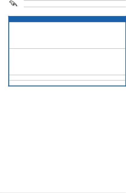
NOTE: Tips and additional information to aid in completing a task.
Where to find more information
Refer to the following sources for additional information and for product and software updates.
1.ASUS Websites
The ASUS websites worldwide provide updated information on ASUS hardware and software products. Refer to the ASUS contact information.
2.Optional Documentation
Your product package may include optional documentation, such as warranty flyers, that may have been added by your dealer. These documents are not part of the standard package.
ix
System package contents
Check your S1-AT5NM10E system package for the following items.
If any of the items is damaged or missing, contact your retailer immediately.
Item description
1.ASUS S1-AT5NM10E barebone system with
•ASUS motherboard
•ASUS ODD (slim type)
•ASUS chassis
•CPU fan
•Chassis fan
2.Accessories
•SATA HDD signal cable x1
•HDD screw x4
•Power adapter x1
•Power cord x1
•ODD bezel x1
3.Support DVD (user manual, drivers, utilities)
4.Quick Installation Guide
Chapter 1
This chapter gives a general description of the ASUS S1-AT5NM10E. The chapter lists the system features including introduction on the front and rear panel, and internal components.
System introduction
1.1Welcome!
Thank you for choosing the ASUS S1-AT5NM10E!
The ASUS S1-AT5NM10E is a slimline barebone system with rich home entertainment features.
The system supports up to 4 GB of system memory using DDR3 SO-DIMMs, HDMI display output, Serial ATA 3Gb/s, USB 3.0, 8-channel audio configuration, and wireless connectivity (WiFi, Bluetooth, and Infrared).
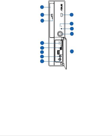
1.2Front panel
1
2 |
13 |
3
12
11
10
4
5
6 
 9
9
7
8
1.Optical disk drive (ODD) (slim type).
2.ODD tray eject button. Push this button to eject the ODD tray.
3.ODD LED.
4.Multimedia Card / Secure Digital™ / MemoryStick™ card slot.
5.6-pin IEEE 1394a port. This port connects to an IEEE 1394a device such as a digital camcorder.
6.USB 3.0 ports. These Universal Serial Bus 3.0 (USB 3.0) ports connect to USB 3.0 / 2.0 devices such as a mouse, printer, scanner, camera, PDA, and others.
7.Microphone port. This port connects to a microphone.
8.Headphone port. This port connects to a pair of headphones or a speaker.
1-2 |
Chapter 1: System introduction |
9.Front I/O ports cover. Open this cover to show the front I/O ports.
10.Power button (with LED). Press this button to turn the system on.
11.HDD LED.
12.Network LED. This network LED is for WiFi / Bluetooth / infrared connections.
13.Infrared (IR) port. Transfer data between the barebone system and an infrared-enabled device using this infrared port.
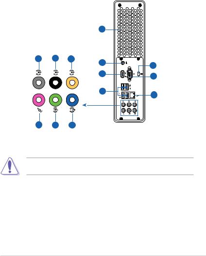
1.3Rear panel
|
|
|
1 |
|
5 |
6 |
7 |
2 |
11 |
|
|
|
||
|
|
|
|
|
|
|
|
3 |
12 |
|
|
|
|
|
|
|
|
4 |
13 |
|
|
|
|
8 9 10
1.Chassis air vents. These vents are for ventilation inside the system chassis.
DO NOT cover the air vents, and use this system in environments with an ambient temperature between 5ºC ~ 35ºC.
2.DC IN port. This port connects to the DC output plug of an AC power adapter.
3.HDMI port. This port connects to a HDMI monitor or other HDMI compatible devices.
4.USB 2.0 ports. These Universal Serial Bus 2.0 (USB 2.0) ports connect to USB 2.0 devices such as a mouse, printer, scanner, camera, PDA, and others.
ASUS S1-AT5NM10E |
1-3 |
5.Side Speaker Out port (gray). This port connects to the side speakers in an
8-channel audio configuration.
6.Rear Speaker Out port (black). This port connects to the rear speakers in a
4-channel, 6-channel, or 8-channel audio configuration.
7.Center / Subwoofer port (orange). This port connects to the center/ subwoofer speakers in a 6-channel or 8-channel audio configuration.
8.Microphone port (pink). This port connects to a microphone.
9.Line Out port (lime). This port connects to a pair of headphones or a speaker. In 4-channel, 6-channel, and 8-channel audio configuration, the function of this port becomes Front Speaker Out.
10.Line In port (light blue). This port connects to the tape, CD, DVD player, or other audio sources.
Refer to the audio configuration table below for the function of the audio ports in 2, 4, 6, or 8-channel configuration.
Audio 2, 4, 6, or 8-channel configuration
Port |
Headset |
4-channel |
6-channel |
8-channel |
|
2-channel |
|||||
|
|
|
|
||
Light Blue |
Line In |
Line In |
Line In |
Line In |
|
Lime |
Line Out |
Front Speaker Out |
Front Speaker Out |
Front Speaker Out |
|
Pink |
Mic In |
Mic In |
Mic In |
Mic In |
|
Orange |
– |
– |
Center/Subwoofer |
Center/Subwoofer |
|
Black |
– |
Rear Speaker Out |
Rear Speaker Out |
Rear Speaker Out |
|
Gray |
– |
– |
– |
Side Speaker Out |
11.Kensington® lock slot. Secure the barebone system to an immovable object using a Kensington® security product.
12.VGA port. This port connects to a VGA monitor or other VGA compatible devices.
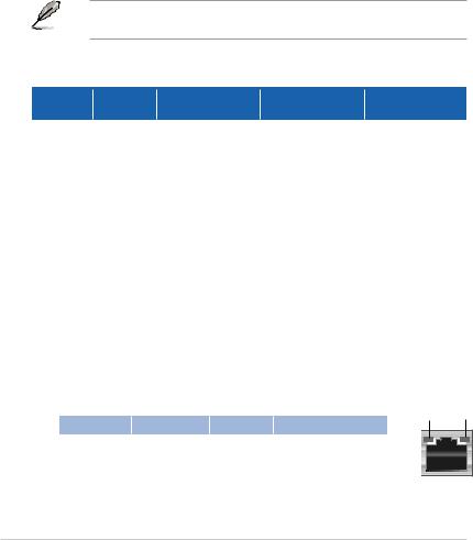
13.LAN (RJ-45) port. This port allows Gigabit connection to a Local Area Network (LAN) through a network hub.
LAN port LED indications
Activity/Link LED |
Speed LED |
|
|
Status |
Description |
Status |
Description |
OFF |
No link |
OFF |
10 Mbps connection |
ORANGE |
Linked |
ORANGE |
100 Mbps connection |
BLINKING |
Data activity |
GREEN |
1 Gbps connection |
ACT/LINK SPEED LED LED
LAN port |
1-4 |
Chapter 1: System introduction |

1.4Internal components
The illustration below shows the internal view of the system when you remove the system covers and the HDD/ODD holder.
1 2
HDD/ODD holder
4 |
5 |
3 |
AT510N3L |
|
6 |
|
|
|
|
|
|
|
|
|
|
|
|
|
|
|
|
|
4. |
CPU fan |
|
|
|
|
|
|
|
|
|
|
|
|
|
|
|
|
|
||
|
|
|
|
|
|
|
|
|
|
|
|
|
|
|
|
|
||
1. |
3.5 inch SATA HDD bay |
|||||||||||||||||
2. |
ODD (slim type) |
5. |
Chassis fan |
|||||||||||||||
3. |
ASUS motherboard |
6. |
204-pin DDR3 SO-DIMM slots |
|||||||||||||||
• Refer to the bundled Quick Installation Guide for installing an SO-DIMM and a hard disk.
•Refer to Chapter 3&4 in this user guide for motherboard details.
ASUS S1-AT5NM10E |
1-5 |
1.5SO-DIMM Qualified Vendors List (QVL)
DDR3 1333MHz capability
Vendor |
Part No. |
Size |
DIMM support |
||
A* |
B* |
||||
|
|
|
|||
HYNIX |
HMT325S6BFR8C-H9(44NM) |
2GB |
• |
• |
|
DIMM support:
• A*: Supports one module inserted into either slot as Single-channel memory configuration.
• B*: Supports one pair of modules inserted into both slots as one pair of Dual-channel memory configuration.
Visit the ASUS website at www.asus.com for the latest QVL.
1-6 |
Chapter 1: System introduction |

Chapter 2
This chapter helps you power up the system and install drivers and utilities from the support DVD.
Starting up

2.1Installing an operating system
The barebone system supports Windows® XP/Vista/7 operating systems (OS). Always install the latest OS version and corresponding updates so you can maximize the features of your hardware.
•Windows XP OS setup cannot recognize Serial ATA hard drives in AHCI
mode or in a RAID set without the necessary drivers. Use a AHCI / RAID driver disk when installing Windows XP OS to a Serial ATA hard drive included in AHCI mode or in a RAID set.
•From the Windows XP setup screen, press F6 when prompted then follow succeeding screen instructions to install the SATA drivers.
2.2Powering up
Press the system power button ( ) to enter the OS.

 Press to turn ON the system
2-2 |
Chapter 2: Starting up |
2.3Support DVD information
The support DVD that came with the system contains drivers and software applications that you can install to enhance the system features.
• Screen display and driver options may not be the same for different operating system versions.
•The contents of the support DVD are subject to change at any time without notice. Visit the ASUS website at www.asus.com for updates.
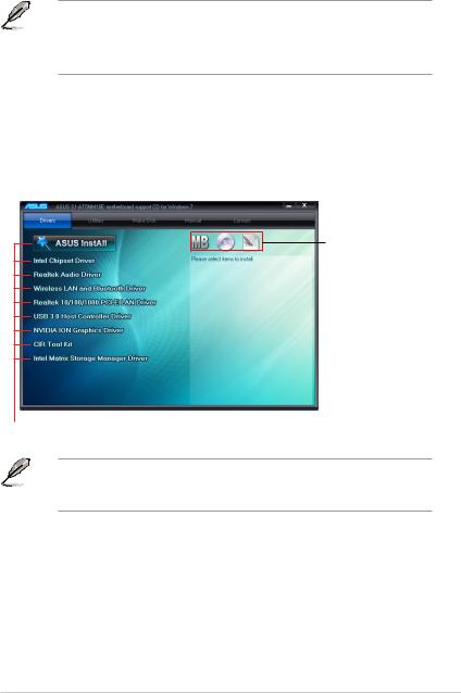
2.3.1Running the support DVD
Place the support DVD into your optical drive. If Autorun is enabled on your computer, the DVD automatically displays the Drivers screen. Click the Drivers, Utilities, Make Disk, Manual, and Contact tabs to display their respective menus.
Click an icon to display support
DVD/motherboard information
Click an item to install
If Autorun is NOT enabled on your computer, browse the contents of the support
DVD to locate the file ASSETUP.EXE from the BIN folder. Double-click the
ASSETUP.EXE to run the DVD.
ASUS S1-AT5NM10E |
2-3 |
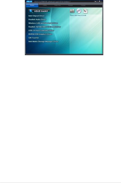
2.3.2Drivers menu
The Drivers menu shows the available device drivers if the system detects installed devices. Install the necessary drivers to activate the devices.
ASUS InstAll
Installs all of the drivers through an installation wizard.
Intel Chipset Driver
Installs the Intel® chipset driver.
Realtek Audio Driver
Installs the Realtek® audio driver and application.
Wireless LAN and Bluetooth Driver
Installs the wireless LAN and Bluetooth driver.
Realtek 10/100/1000 PCI-E LAN Driver
Installs the Realtek® 10/100/1000 PCI-E LAN driver.
USB 3.0 Host Controller Driver
Installs the USB 3.0 host controller driver.
NVIDIA ION Graphics Driver
Installs the NVIDIA® ION graphics driver.
CIR Tool Kit
Installs the CIR (Consumer Infrared) tool kit.
Intel Matrix Storage Manager Driver
Installs the Intel® Matrix Storage Manager driver.
2-4 |
Chapter 2: Starting up |
2.3.3Utilities menu
The Utilities menu shows the applications and other software that the motherboard supports.
ASUS InstAll
Installs all of the utilities through an installation wizard.
ASUS Update
Allows you to download the latest version of the BIOS from the ASUS website.
ASUS AI Manager
Installs the ASUS AI Manager.
ASUS Express Gate Installer
Installs the ASUS Express Gate.
Realtek Ethernet Utility
Installs the Realtek® Ethernet utility.
Adobe Reader 9
Installs the Adobe® Reader that allows you to open, view, and print documents in Portable Document Format (PDF).
Internet Radio
installs the Internet Radio utility.
PC-cillin 2010
Installs the PC-cillin utility.
ASUS S1-AT5NM10E |
2-5 |
 Loading...