


P5LP-LE
(Leonite)
Motherboard

E2905
First Edition V1
October 2006
Contents
P5LP-LE (Leonite) specifications summary |
........................................ iii |
||
1. |
Motherboard layout ................................................................. |
1 |
|
2. |
Central Processing Unit (CPU) ................................................. |
2 |
|
3. |
System memory ...................................................................... |
5 |
|
4. |
Expansion slots ........................................................................ |
8 |
|
5. |
Jumpers |
................................................................................. |
11 |
6. |
Connectors ............................................................................ |
12 |
|
|
6.1 |
Rear panel connectors ............................................. |
12 |
|
6.2 |
Internal connectors.................................................. |
14 |
ii

P5LP-LE specifications summary
C P U
Chipset
Front Side Bus (FSB)
Memory
Expansion slots
Rear panel
Internal connectors
Storage
LGA775 socket for the Intel® Pentium® 4 and Conroe processor in the 775-land package
Northbridge: Intel® 945G Graphics Memory and
Controller Hub (GMCH)
Southbridge: Intel® ICH7DH
1066 MHz
Dual-channel memory architecture
4 x 240-pin DIMM sockets support unbuffered non-ECC 4 GB 667/533/400 MHZ DDR2 memory modules
1 x PCI Express™ x16 slot for discrete graphics card 3 x PCI slots
1 x PS/2 keyboard port
1 x PS/2 mouse port
1 x IEEE 1394a port
1 x LAN (RJ-45) port
6 x audio ports support 8-channel audio configuration 4 x USB 2.0 ports support hot-plug function
1 x VGA port
1 x Coaxial SPDIF out port
1 x Coaxial SPDIF in port
1 x Floppy connector
1 x IDE connector
1 x 24-pin ATX power connector
1 x 4-pin ATX 12 V power connector 4 x Serial ATA connectors
1 x IEEE 1394a connector
2 x USB 2.0 connectors
1 x CPU fan connector
1 x System fan connector
1 x Internal audio connector
1 x Digital audio connector
1 x Front headphone connector
1 x System panel connector
Southbridge supports:
-2 x Ultra DMA 100/66 hard disk drives
-4 x Serial ATA hard disk drives with hot-swap function
(continued on the next page)
i i i

P5LP-LE specifications summary
Audio
L A N
IEEE 1394
PC health monitoring
BIOS features
Form factor
Southbridge supports 8-channel audio configuration with Intel® High Definition Audio CODEC
Realtek ALC888 High Definition Audio CODEC
Intel® 82562GT 10/100 Mbps Fast Ethernet
LAN PHY
Agere LFW3227 two IEEE 1394a ports
ASUS F8000 for CPU, system, and chassis fan control, motherboard and CPU temperature
4 Mb SPI Flash ROM
HP BIOS with enhanced ACPI, DMI, Green, and PnP Features Plus
Micro-ATX form factor: 9.6 in x 9.6 in
* Specifications are subject to change without notice
i v

1.Motherboard layout
|
|
|
24.5cm (9.6in) |
|
|
|
|
|
|
|
|
PS/2KBMS |
|
|
|
|
|
|
|
|
CLPWD |
|
|
|
|
|
|
|
|
|
|
|
|
||
T: Mouse |
|
|
|
|
|
|
|
|
|
|
|
B: Keyboard |
|
|
|
|
|
|
|
|
|
|
|
|
|
|
|
|
|
|
|
|
F8000 |
|
|
|
SPDIF |
|
LGA775 |
|
|
|
|
|
|
|
|
|
|
|
|
|
|
|
|
|
|
|
|
|
|
|
|
|
module) |
module) |
module) |
module) |
|
|
|
VGA |
|
|
|
|
(64 bit,240-pin |
(64 bit,240-pin |
(64 bit,240-pin |
(64 bit,240-pin |
|
|
|
Bottom: Top: |
ATX12V |
|
|
ATXPWR |
FLOPPY |
|
|||||
T:USB1 |
|
|
LE-P5LP |
XMM1DDR2 |
XMM2DDR2 |
XMM3DDR2 |
XMM4DDR2 |
|
IDE |
(9.6in)24.5cm |
|
B:USB2 1394 |
|
|
|
||||||||
|
|
|
|
|
|
|
|
|
|
||
USB2.0 |
Top: |
|
SYS_FAN3 |
|
|
|
|
|
|
|
|
T: USB3 |
RJ-45 |
CPU_FAN |
|
|
|
|
|
|
|
|
|
B: USB4 |
|
Intel® |
|
|
|
|
|
|
|
|
|
|
|
|
|
|
|
|
|
|
|
||
|
|
|
945G |
|
|
|
|
|
|
|
|
|
|
Top: |
GMCH |
|
|
|
|
|
|
|
|
|
Subwoofer Speaker Out |
|
|
|
|
|
|
|
|
|
|
|
|
Center |
|
|
|
|
|
|
|
|
|
Top:Line In |
|
Rear Speaker Out |
|
|
|
|
|
|
|
|
|
Center:Line Out |
Below |
|
|
|
|
|
|
|
|
|
|
Side Speaker Out |
|
|
|
|
|
|
|
|
|
||
Below:Mic In |
|
|
|
|
|
|
|
|
|
||
|
|
|
|
|
|
|
|
|
|
||
PCIEX16
|
|
|
|
|
|
|
|
|
|
|
|
|
|
|
|
|
|
|
|
|
|
|
|
|
|
CR2032 3V |
|
||||||||
PCI1 |
|
|
|
|
|
|
|
Lithium Cell |
|
||||||||
|
|
|
Intel® |
|
|
|
CMOS Power |
|
|||||||||
|
|
|
|
|
|
|
|
|
|
|
|
CLRTC |
|
||||
PCI2 |
|
|
|
ICH7DH |
|
|
SATA2 |
SATA4 |
|
||||||||
|
Agere |
|
|||||||||||||||
|
|
|
|
|
SATA1 |
SATA3 |
|
||||||||||
|
|
LFW3227 |
|
|
|
|
|||||||||||
|
|
|
|||||||||||||||
ALC888 |
PC3 |
|
|
|
|
|
|
|
|
|
|
|
|
||
|
|
|
|
|
|
|
SPDIF2 |
F_LINE_IN |
F_1394 |
FRONT_USB1 |
BUZZ1 |
F_PANEL |
|
F_AUDIO |
|
FRONT_USB2 |
|
|
|
|
|
|
|
ASUS P5LP-LE (Leonite) |
1 |
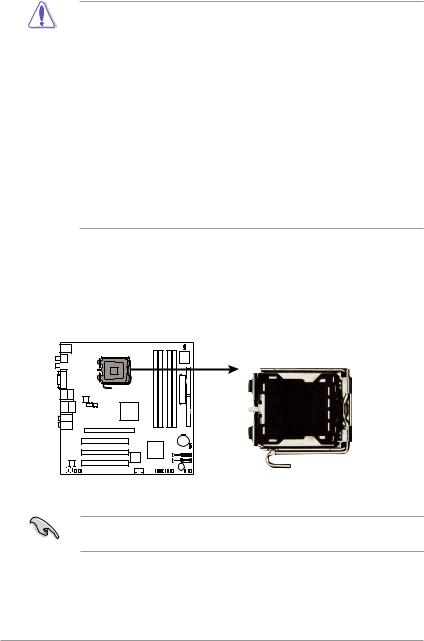
2.Central Processing Unit (CPU)
The motherboard comes with a surface mount LGA775 socket designed for the Intel® Pentium® 4 and Conroe processor in the 775-land package.
•Your boxed Intel® Pentium® 4 processor package should
come with installation instructions for the CPU, heatsink, and the retention mechanism. If the instructions in this section do not match the CPU documentation, follow the latter.
•Upon purchase of the motherboard, make sure that the PnP cap is on the socket and the socket contacts are not bent. Contact your retailer immediately if the PnP cap is missing, or if you see any damage to the PnP cap/socket contacts/motherboard components. ASUS will shoulder the cost of repair only if the damage is shipment/ transit-related.
•Keep the cap after installing the motherboard. ASUS will process Return Merchandise Authorization (RMA) requests only if the motherboard comes with the cap on the LGA775 socket.
•The product warranty does not cover damage to the socket contacts resulting from incorrect CPU installation/removal, or misplacement/loss/incorrect removal of the PnP cap.
Installing the CPU
To install a CPU:
1.Locate the CPU socket on the motherboard.
P5LP-LE
P5LP-LE (Leonite) CPU Socket 775
Before installing the CPU, make sure that the socket box is facing towards you and the load lever is on your left.
2 |
ASUS P5LP-LE (Leonite) |
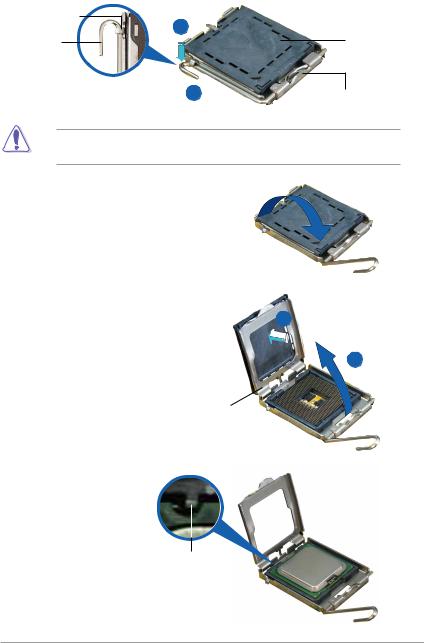
2.Press the load lever with your thumb (A), then move it to the left (B) until it is released from the retention tab.
Retention tab
A
Loa d lever
Pn P cap
BThis side of the socket box should fac e you .
To prevent damage to the socket pins, do not remove the PnP cap unless you are installing a CPU.
3.Lift the load lever in the direction of the arrow to a 135º angle.
4.Lift the load plate with your
thumb and forefinger to a |
B |
100º angle (A), then push |
|
the PnP cap from the load |
|
plate window to remove (B). |
A |
|
Loa d plate |
5.Position the CPU over the socket, making sure that the gold triangle is on the bottom-left corner of the socket. The socket alignment key should fit into the CPU notch.
Alignment key
Gold triangle mark 
ASUS P5LP-LE (Leonite) |
3 |
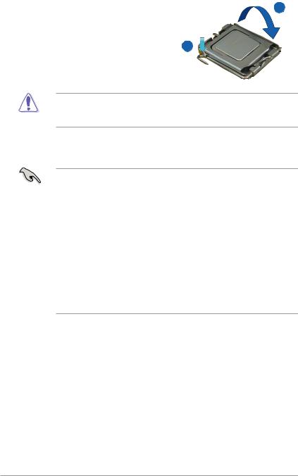
6.Close the load plate (A), then push the load lever (B) until it snaps into the retention tab.
B
The CPU fits in only one correct orientation. DO NOT force the CPU into the socket to prevent bending the connectors on the socket and damaging the CPU!
Notes on Intel® Hyper-Threading Technology
• This motherboard supports Intel® Pentium® 4 processor in the 775-land package with Hyper-Threading Technology.
•Hyper-Threading Technology is supported under Windows® XP/2003 Server and Linux 2.4.x (kernel) and later versions only. Under Linux, use the Hyper-Threading compiler to compile the code. If you are using any other operating systems, disable the Hyper-Threading Techonology item in the BIOS to ensure system stability and performance.
•Installing Windows® XP Service Pack 1 or later version is recommended.
•Make sure to enable the Hyper-Threading Technology item in BIOS before installing a supported operating system.
•For more information on Hyper-Threading Technology, visit www.intel.com/info/hyperthreading.
To use the Hyper-Threading Technology on this motherboard:
1.Install an Intel® Intel® Pentium® 4 processor that supports Hyper-Threading Technology.
2.Power up the system and enter the BIOS Setup. Under the Advanced Menu, make sure that the item Hyper-Threading Technology is set to Enabled. The item appears only if you installed a CPU that supports Hyper-Threading Techonology.
3.Reboot the computer.
4 |
ASUS P5LP-LE (Leonite) |
 Loading...