


ASUS Desktop PC
BM6675(MD750)
BM6875
BP6375(SD750)
BM6675(MD750) |
BM6875 |
BP6375(SD750)
User Manual

E7696
Second Edition
October 2012
Copyright © 2012 ASUSTeK Computer Inc. All Rights Reserved.
No part of this manual, including the products and software described in it, may be reproduced, transmitted, transcribed, stored in a retrieval system, or translated into any language in any form or by any means, except documentation kept by the purchaser for backup purposes, without the express written permission of ASUSTeK Computer Inc. (“ASUS”).
Product warranty or service will not be extended if: (1) the product is repaired, modified or altered, unless such repair, modification of alteration is authorized in writing byASUS; or (2) the serial number of the product is defaced or missing.
ASUS PROVIDES THIS MANUAL “AS IS” WITHOUT WARRANTY OF ANY KIND, EITHER EXPRESS OR IMPLIED, INCLUDING BUT NOT LIMITED TO THE IMPLIED WARRANTIES OR CONDITIONS OF MERCHANTABILITY OR FITNESS FOR A PARTICULAR PURPOSE. IN NO EVENT SHALL ASUS, ITS DIRECTORS, OFFICERS, EMPLOYEES OR AGENTS BE LIABLE FOR ANY INDIRECT, SPECIAL, INCIDENTAL, OR CONSEQUENTIAL DAMAGES (INCLUDING DAMAGES FOR LOSS OF PROFITS, LOSS OF BUSINESS, LOSS OF USE OR DATA, INTERRUPTION OF BUSINESS AND THE LIKE), EVEN IF ASUS HAS BEEN ADVISED OF THE POSSIBILITY OF SUCH DAMAGES ARISING FROM ANY DEFECT OR ERROR IN THIS MANUAL OR PRODUCT.
SPECIFICATIONS AND INFORMATION CONTAINED IN THIS MANUAL ARE FURNISHED FOR INFORMATIONAL USE ONLY, AND ARE SUBJECT TO CHANGE AT ANY TIME WITHOUT NOTICE, AND SHOULD NOT BE CONSTRUED AS A COMMITMENT BY ASUS. ASUS ASSUMES NO RESPONSIBILITY OR LIABILITY FOR ANY ERRORS OR INACCURACIES THAT MAY APPEAR IN THIS MANUAL, INCLUDING THE PRODUCTS AND SOFTWARE DESCRIBED IN IT.
Products and corporate names appearing in this manual may or may not be registered trademarks or copyrights of their respective companies, and are used only for identification or explanation and to the owners’ benefit, without intent to infringe.

Contents |
|
|
Notices ........................................................................................................... |
|
5 |
Safety information.......................................................................................... |
|
8 |
Conventions used in this guide...................................................................... |
9 |
|
Where to find more information...................................................................... |
9 |
|
Package contents......................................................................................... |
|
10 |
Chapter 1: |
Getting started |
|
Welcome!...................................................................................................... |
|
11 |
Getting to know your computer..................................................................... |
11 |
|
Setting up your computer............................................................................. |
21 |
|
Turning your computer ON/OFF................................................................... |
26 |
|
Chapter 2: |
Using Windows® 7 |
|
Starting for the first time............................................................................... |
27 |
|
Using Windows® 7 desktop.......................................................................... |
28 |
|
Managing your files and folders................................................................... |
30 |
|
Restoring your system settings.................................................................... |
32 |
|
Protecting your computer............................................................................. |
33 |
|
Getting Windows® Help and Support............................................................ |
34 |
|
Chapter 3: |
Using Windows® 8 |
|
Starting for the first time............................................................................... |
35 |
|
Using the Windows® UI................................................................................ |
36 |
|
Working with Windows® apps....................................................................... |
39 |
|
Other keyboard shortcuts............................................................................. |
44 |
|
Turning your Desktop PC OFF..................................................................... |
45 |
|
Putting your Desktop PC to sleep................................................................ |
45 |
|
Entering the BIOS Setup.............................................................................. |
46 |
|
Chapter 4: |
Connecting devices to your computer |
|
Connecting a USB storage device............................................................... |
47 |
|
Connecting microphone and speakers......................................................... |
50 |
|
Chapter 5: |
Using your computer |
|
Proper posture when using your Desktop PC.............................................. |
55 |
|
Using the optical drive (on selected models only)........................................ |
56 |
|
Configuring the USB ports using the BIOS.................................................. |
57 |
|
Configuring the HDD security setting using the BIOS.................................. |
58 |
|

Contents |
|
|
Chapter 6: |
Connecting to the Internet |
|
Wired connection |
.......................................................................................... |
59 |
Chapter 7: |
Using the utilities |
|
ASUS AI Suite II........................................................................................... |
|
69 |
ASUS WebStorage....................................................................................... |
76 |
|
ASUS Easy Update...................................................................................... |
88 |
|
ASUS Secure Delete.................................................................................... |
89 |
|
ASUS Business Suite................................................................................... |
91 |
|
Nero 9 ......................................................................................................... |
|
93 |
Recovering your system............................................................................... |
94 |
|
Chapter 8: |
Troubleshooting |
|
Troubleshooting............................................................................................ |
|
97 |
ASUS contact information.......................................................................... |
105 |
|
Notices
ASUS Recycling/Takeback Services
ASUS recycling and takeback programs come from our commitment to the highest standards for protecting our environment. We believe in providing solutions for you to be able to responsibly recycle our products, batteries, other components, as well as the packaging materials. Please go to http://csr.asus.com/english/Takeback.htm for the detailed recycling information in different regions.
REACH
Complying with the REACH (Registration, Evaluation, Authorisation, and Restriction of Chemicals) regulatory framework, we published the chemical substances in our products at ASUS REACH website at http://csr.asus.com/english/REACH.htm
Federal Communications Commission Statement
This device complies with Part 15 of the FCC Rules. Operation is subject to the following two conditions:
•This device may not cause harmful interference; and
•This device must accept any interference received including interference that may cause undesired operation.
This equipment has been tested and found to comply with the limits for a Class B digital device, pursuant to Part 15 of the FCC Rules. These limits are designed to provide reasonable protection against harmful interference in a residential installation. This equipment generates, uses and can radiate radio frequency energy and, if not installed and used in accordance with manufacturer’s instructions, may cause harmful interference to radio communications. However, there is no guarantee that interference will not occur in a particular installation. If this equipment does cause harmful interference to radio or
television reception, which can be determined by turning the equipment off and on, the user is encouraged to try to correct the interference by one or more of the following measures:
•Reorient or relocate the receiving antenna.
•Increase the separation between the equipment and receiver.
•Connect the equipment to an outlet on a circuit different from that to which the receiver is connected.
•Consult the dealer or an experienced radio/TV technician for help.
The use of shielded cables for connection of the monitor to the graphics card is required to assure compliance with FCC regulations. Changes or modifications to this unit not expressly approved by the party responsible for compliance could void the user’s authority to operate this equipment.
Lithium Battery Warning
CAUTION: Danger of explosion if battery is incorrectly replaced. Replace only with the same or equivalent type recommended by the manufacturer. Dispose of used batteries according to the manufacturer’s instructions.
IC: Canadian Compliance Statement
Complies with the Canadian ICES-003 Class B specifiications. This device complies with RSS
210 of Industry Canada. This Class B device meets all the requirements of the Canadian interference-causing equipment regulations.
This device complies with Industry Canada license exempt RSS standard(s). Operation is subject to the following two conditions: (1) this device may not cause interference, and (2) this device must accept any interference, including interference that may cause undesired operation of the device.
Cut appareil numérique de la Classe B est conforme à la norme NMB-003 du Canada. Cet appareil numérique de la Classe B respecte toutes les exigences du Règlement sur le matériel brouilleur du Canada.
Cet appareil est conforme aux normes CNR exemptes de licence d’Industrie Canada. Le fonctionnement est soumis aux deux conditions suivantes :
(1)cet appareil ne doit pas provoquer d’interférences et
(2)cet appareil doit accepter toute interférence, y compris celles susceptibles de provoquer un fonctionnement non souhaité de l’appareil.
Canadian Department of Communications Statement
This digital apparatus does not exceed the Class B limits for radio noise emissions from digital apparatus set out in the Radio Interference Regulations of the Canadian Department of Communications.
This class B digital apparatus complies with Canadian ICES-003.
VCCI: Japan Compliance Statement VCCI Class B Statement
KC: Korea Warning Statement
RF Equipment Notices
CE: European Community Compliance Statement
The equipment complies with the RF Exposure Requirement 1999/519/EC, Council Recommendation of 12 July 1999 on the limitation of exposure of the general public to electromagnetic fields (0–300 GHz). This wireless device complies with the R&TTE Directive.
Wireless Radio Use
This device is restricted to indoor use when operating in the 5.15 to 5.25 GHz frequency band.
Exposure to Radio Frequency Energy
The radiated output power of the Wi-Fi technology is below the FCC radio frequency exposure limits. Nevertheless, it is advised to use the wireless equipment in such a manner that the potential for human contact during normal operation is minimized.
FCC Bluetooth Wireless Compliance
The antenna used with this transmitter must not be colocated or operated in conjunction with any other antenna or transmitter subject to the conditions of the FCC Grant.
Bluetooth Industry Canada Statement
This Class B device meets all requirements of the Canadian interference-causing equipment regulations.
Cet appareil numérique de la Class B respecte toutes les exigences du Règlement sur le matériel brouilleur du Canada.
BSMI: Taiwan Wireless Statement
Japan RF Equipment Statement
KC (RF Equipment)

Safety information
Disconnect the AC power and peripherals before cleaning. Wipe the Desktop PC using a clean cellulose sponge or chamois cloth dampened with solution of nonabrasive detergent and a few drops of warm water then remove any extra moisture with a dry cloth.
•DO NOT place on uneven or unstable work surfaces. Seek servicing if the casing has been damaged.
•DO NOT expose to dirty or dusty environments. DO NOT operate during a gas leak.
•DO NOT place or drop objects on top and do not shove any foreign objects into the Desktop PC.
•DO NOT expose to strong magnetic or electrical fields.
•DO NOT expose to or use near liquids, rain, or moisture. DO NOT use the modem during electrical storms.
•Battery safety warning: DO NOT throw the battery in fire. DO NOT short circuit the contacts. DO NOT disassemble the battery.
•Use this product in environments with ambient temperatures between 5˚C (41̊F) and 40˚C (104̊F).
•DO NOT cover the vents on the Desktop PC to prevent the system from getting overheated.
•DO NOT use damaged power cords, accessories, or other peripherals.
•To prevent electrical shock hazard, disconnect the power cable from the electrical outlet before relocating the system.
•Seek professional assistance before using an adapter or extension cord. These devices could interrupt the grounding circuit.
•Ensure that your power supply is set to the correct voltage in your area. If you are not sure about the voltage of the electrical outlet you are using, contact your local power company.
•If the power supply is broken, do not try to fix it by yourself. Contact a qualified service technician or your retailer.
Conventions used in this guide
To ensure that you perform certain tasks properly, take note of the following symbols used throughout this manual.
DANGER/WARNING: Information to prevent injury to yourself when trying to complete a task.
CAUTION: Information to prevent damage to the components when trying to complete a task.
IMPORTANT: Instructions that you MUST follow to complete a task.
NOTE: Tips and additional information to help you complete a task.
Where to find more information
Refer to the following sources for additional information and for product and software updates.
ASUS websites
The ASUS website provides updated information on ASUS hardware and software products. Refer to the ASUS website www.asus.com.
ASUS Local Technical Support
Visit ASUS website at http://support.asus.com/contact for the contact information of local Technical Support Engineer.
• The user manual is located in the following folder in your Desktop PC:
• C:\Program Files(X86)\ASUS\eManual
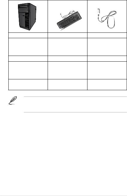
Package contents
|
|
|
|
|
|
|
|
|
|
|
|
|
|
|
|
|
|
|
|
|
ASUS Desktop PC |
Keyboard x1 |
Mouse x1 |
||||
|
|
|
|
|
|
|
|
|
|
|
|
|
|
Power cord x1 |
Support DVD x1 |
Recovery DVD x1 (Optional) |
|
InstallationGuide |
|
Nero 9 burning software |
Installation Guide x1 |
Warranty card x1 |
DVD x1 (Optional) |
|
|
•If any of the above items is damaged or missing, contact your retailer.
•The illustrated items above are for reference only.Actual product specifications may vary with different models.
10
Chapter 1
Getting started
Welcome!
Thank you for purchasing the ASUS Desktop PC!
The ASUS Desktop PC provides cutting-edge performance, uncompromised reliability, and user-centric utilities. All these values are encapsulated in a stunningly futuristic and stylish system casing.
Read the ASUS Warranty Card before setting up your ASUS Desktop PC.
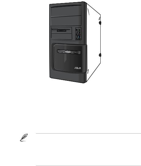
Getting to know your computer
Illustrations are for reference only. The ports and their locations, and the chassis color vary with different models.
ASUS BM6675(MD750), BM6875, and BP6375(SD750) |
11 |
ENGLISH
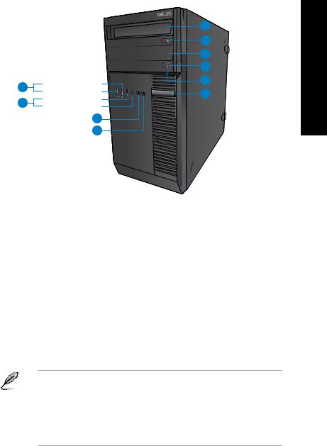
Front panel
10
9
8
1
2
3
6
7
Front USB 2.0 port 3 Front USB 2.0 port 4 Front USB 3.0 port 1 Front USB 3.0 port 2
4
 5
5
BM6675(MD750)
1.2 x 5.25 inch optical disk drive bays. The 5.25 inch optical disk drive bays are for 5.25 inch DVD-ROM / CD-RW / DVD-RW devices.
2.Microphone port (pink). This port connects to a microphone.
3.Headphone port (lime). This port connects to a headphone or speaker.
4.USB 2.0 ports. These Universal Serial Bus 2.0 (USB 2.0) ports connect to USB 2.0 devices such as a mouse, printer, scanner, camera, PDA, and others.
5.USB 3.0 ports. These Universal Serial Bus 3.0 (USB 3.0) ports connect to USB 3.0 devices such as a mouse, printer, scanner, camera, PDA, and others.
• DO NOT connect a keyboard / mouse to any USB 3.0 port when installing Windows® operating system.
•Due to USB 3.0 controller limitation, USB 3.0 devices can only be used under Windows® OS environment and after the USB 3.0 driver installation.
•USB 3.0 devices can only be used as data storage only.
•We strongly recommend that you connect USB 3.0 devices to USB 3.0 ports for faster and better performance for your USB 3.0 devices.
6.Reset button. Press this button to reboot your computer.
7.HDD LED. This LED lights up when the hard disk drive operates.
8.Power LED. This LED lights up when you turn on your computer.
9.Power button. Press this button to turn on your computer.
10.2 x 3.5 inch drive bays. The 3.5 inch drive bays are for 3.5 inch hard disk drives / memory card readers.
12 |
Chapter 1: Getting started |
|
|
1 |
|
|
2 |
|
|
3 |
|
|
2 |
9 |
Front USB 3.0 port 1 |
4 |
Front USB 3.0 port 2 |
5 |
|
8 |
Front USB 2.0 port 3 |
|
Front USB 2.0 port 4 |
|
|
|
|
7
6
BM6875
1.5.25 inch optical disk drive bay. The 5.25 inch optical disk drive bay is for 5.25 inch DVD-ROM / CD-RW / DVD-RW devices.
2.Optical disk drive eject button. Press this button to eject the optical disk drive tray.
3.Optical disk drive bay (empty). You may install an additional optical disk drive in this bay.
4.HDD LED. This LED lights up when the hard disk drive operates.
5.Power button. Press this button to turn on your computer.
6.Microphone. This port connects to a microphone.
7.Headphone port. This port connects to a headphone or speaker.
8.USB 2.0 ports. These Universal Serial Bus 2.0 (USB 2.0) ports connect to USB 2.0 devices such as a mouse, printer, scanner, camera, PDA, and others.
9.USB 3.0 ports. These Universal Serial Bus 3.0 (USB 3.0) ports connect to USB 3.0 devices such as a mouse, printer, scanner, camera, PDA, and others.
• DO NOT connect a keyboard / mouse to any USB 3.0 port when installing Windows® operating system.
•Due to USB 3.0 controller limitation, USB 3.0 devices can only be used under Windows® OS environment and after the USB 3.0 driver installation.
•USB 3.0 devices can only be used as data storage only.
•We strongly recommend that you connect USB 3.0 devices to USB 3.0 ports for faster and better performance for your USB 3.0 devices.
ENGLISH
ASUS BM6675(MD750), BM6875, and BP6375(SD750) |
13 |
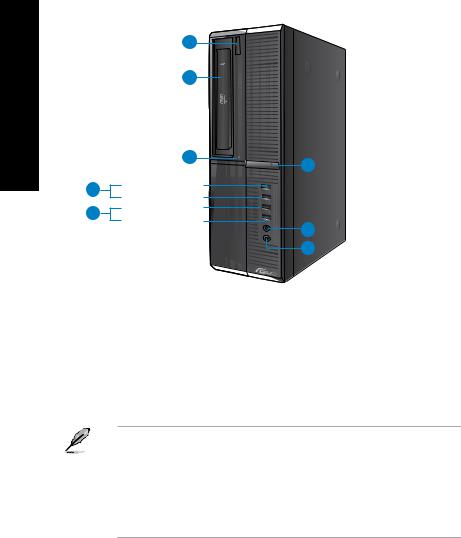
ENGLISH
1
2
|
3 |
8 |
|
|
|
||
4 |
Front USB 3.0 port 2 |
|
|
Front USB 3.0 port 1 |
|
||
|
|
||
5 |
Front USB 2.0 port 3 |
|
|
Front USB 2.0 port 4 |
7 |
||
|
|||
|
|
||
|
|
6 |
BP6375(SD750)
1.Optical disk drive eject button. Press this button to eject the optical disk drive tray.
2.5.25 inch optical disk drive bay. The 5.25 inch optical disk drive bay is for 5.25 inch DVD-ROM / CD-RW / DVD-RW devices.
3.HDD LED. This LED lights up when the hard disk drive operates.
4.USB 3.0 ports. These Universal Serial Bus 3.0 (USB 3.0) ports connect to USB 3.0 devices such as a mouse, printer, scanner, camera, PDA, and others.
• DO NOT connect a keyboard / mouse to any USB 3.0 port when installing Windows® operating system.
•Due to USB 3.0 controller limitation, USB 3.0 devices can only be used under Windows® OS environment and after the USB 3.0 driver installation.
•USB 3.0 devices can only be used as data storage only.
•We strongly recommend that you connect USB 3.0 devices to USB 3.0 ports for faster and better performance for your USB 3.0 devices.
5.USB 2.0 ports. These Universal Serial Bus 2.0 (USB 2.0) ports connect to USB 2.0 devices such as a mouse, printer, scanner, camera, PDA, and others.
6.Microphone. This port connects to a microphone.
7.Headphone port. This port connects to a headphone or speaker.
8.Power button. Press this button to turn on your computer.
14 |
Chapter 1: Getting started |

Rear panel
|
|
1 |
|
2 |
14 |
|
|
|
|
3 |
17 |
|
4 |
|
|
16 |
|
|
|
|
|
5 |
|
7 |
6 |
15 |
Rear USB 3.0 port 2 |
14 |
|
|
Rear USB 3.0 port 1 |
|
8 |
Rear USB 2.0 port 3 |
13 |
Rear USB 2.0 port 4 |
|
|
12 |
9 |
10 |
11 |
|
BM6675(MD750) |
1. |
Power connector. Plug the power cord to this connector. |
2 . |
Voltage selector. Use this switch to select the appropriate system input voltage |
|
according to the voltage supply in your area. If the voltage supply in your area is 100- |
|
127V, set the switch to 115V. If the voltage supply in your area is 200-240V, set the |
|
switch to 230V. |
Setting the switch to 115V in a 230V environment or 230V in a 115V environment will seriously damage the system!
3.PS/2 mouse port (green). This port is for a PS/2 mouse.
4.PS/2 keyboard port (purple). This port is for a PS/2 keyboard.
5.DisplayPort. This port connects a display monitor or home-theater system.
DisplayPort cannot be converted to DVI and HDMI.
6.DVI-D port. This port is for any DVI-D compatible device and is HDCP compliant allowing playback of HD DVD, Blu-ray, and other protected content.
7.USB 3.0 ports. These Universal Serial Bus 3.0 (USB 3.0) ports connect to USB 3.0 devices such as a mouse, printer, scanner, camera, PDA, and others.
ENGLISH
ASUS BM6675(MD750), BM6875, and BP6375(SD750) |
15 |

|
|
|
|
|
• DO NOT connect a keyboard / mouse to any USB 3.0 port when installing Windows® |
|||||
ENGLISH |
|
|
|
|
operating system. |
|
|
|
|
|
|
|
|
|
and better performance for your USB 3.0 devices. |
|
|
|
|||
|
|
|
|
|
• Due to USB 3.0 controller limitation, USB 3.0 devices can only be used under Windows® |
|||||
|
|
|
|
|
OS environment and after the USB 3.0 driver installation. |
|
|
|||
|
|
|
|
|
• USB 3.0 devices can only be used as data storage only. |
|
|
|||
|
|
|
|
|
• We strongly recommend that you connect USB 3.0 devices to USB 3.0 ports for faster |
|||||
|
|
|
|
|
|
|
|
|
|
|
|
8. |
|
USB 2.0 ports. These Universal Serial Bus 2.0 (USB 2.0) ports connect to USB 2.0 |
|||||||
|
|
|
devices such as a mouse, printer, scanner, camera, PDA, and others. |
|
|
|||||
|
9. |
|
Microphone port (pink). This port connects to a microphone. |
|
|
|||||
|
10. |
|
Line Out port (lime). This port connects to a headphone or speaker. In a 4, 6, or |
|||||||
|
|
|
8-channel configuration, the function of this port becomes Front Speaker Out. |
|||||||
11. |
|
Line In port (light blue). This port connects to a tape, CD, DVD player, or other audio |
||||||||
|
|
|
sources. |
|
|
|
|
|
||
|
|
|
|
|
|
|
|
|
|
|
|
|
|
|
Refer to the audio configuration table below for the function of the audio ports in the 2, 4, 6, |
||||||
|
|
|
|
or 8-channel configuration. |
|
|
|
|
||
|
|
Audio 2, 4, 6, or 8-channel configuration |
|
|
|
|||||
|
|
|
|
|
|
|
|
|
|
|
|
|
|
|
|
Port |
Headset 2-channel |
4-channel |
6-channel |
8-channel |
|
|
|
|
Light Blue (Rear panel) |
Line In |
Rear Speaker Out |
Rear Speaker Out |
Rear Speaker Out |
|||
|
|
|
Lime (Rear panel) |
Line Out |
Front Speaker Out |
Front Speaker Out |
Front Speaker Out |
|||
|
|
|
Pink (Rear panel) |
Mic In |
Mic In |
Bass/Center |
Bass/Center |
|||
|
|
|
Lime (Front panel) |
- |
- |
- |
Side Speaker Out |
|||
12.Expansion slot brackets. Remove the expansion slot bracket when installing an expansion card.
13.LAN (RJ-45) port. This port allows Gigabit connection to a Local Area Network (LAN) through a network hub.
LAN port LED indications |
|
|
ACT/LINK SPEED |
|||||
|
|
|
|
LED |
|
LED |
|
|
Activity/Link LED |
Speed LED |
|
||||||
Status |
Description |
Status |
Description |
|
|
|
|
|
OFF |
No link |
OFF |
10Mbps connection |
|
|
|
|
|
|
|
|
|
|
|
|
|
|
ORANGE |
Linked |
ORANGE |
100Mbps connection |
|
|
|
|
|
BLINKING |
Data activity |
GREEN |
1Gbps connection |
|
|
|
|
|
|
|
|
|
|
|
|
|
|
|
|
|
|
|
|
|
|
|
14. Air vents. |
These vents allow air ventilation. |
LAN port |
|
DO NOT block the air vents on the chassis. Always provide proper ventilation for your computer.
15.VGA port. This port is for VGA-compatible devices such as a VGA monitor.
16 |
Chapter 1: Getting started |
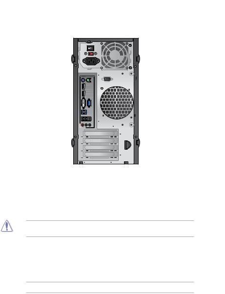
16.Parallel Port (optional). This port connects a parallel printer, a scanner, or other devices.
17.Serial port (optional). This COM1 port is for pointing devices or other serial devices.
|
|
1 |
|
2 |
15 |
|
|
|
|
3 |
|
|
4 |
18 |
|
5 |
17 |
|
6 |
|
|
7 |
16 |
8 |
Rear USB 3.0 port 2 |
15 |
Rear USB 3.0 port 1 |
||
9 |
Rear USB 2.0 port 3 |
14 |
Rear USB 2.0 port 4 |
13
10 11 12
BM6875
1.Power switch. Switch to turn ON/OFF the power supply to your computer.
2 . |
Voltage selector. Use this switch to select the appropriate system input voltage |
|
according to the voltage supply in your area. If the voltage supply in your area is 100- |
|
127V, set the switch to 115V. If the voltage supply in your area is 200-240V, set the |
|
switch to 230V. |
Setting the switch to 115V in a 230V environment or 230V in a 115V environment will seriously damage the system!
3.Power connector. Plug the power cord to this connector.
4.PS/2 mouse port (green). This port is for a PS/2 mouse.
5.PS/2 keyboard port (purple). This port is for a PS/2 keyboard.
6.DisplayPort. This port connects a display monitor or home-theater system.
DisplayPort cannot be converted to DVI and HDMI.
7.DVI-D port. This port is for any DVI-D compatible device and is HDCP compliant allowing playback of HD DVD, Blu-ray, and other protected content.
ENGLISH
ASUS BM6675(MD750), BM6875, and BP6375(SD750) |
17 |
ENGLISH
8.USB 3.0 ports. These Universal Serial Bus 3.0 (USB 3.0) ports connect to USB 3.0 devices such as a mouse, printer, scanner, camera, PDA, and others.
• DO NOT connect a keyboard / mouse to any USB 3.0 port when installing Windows® operating system.
•Due to USB 3.0 controller limitation, USB 3.0 devices can only be used under Windows® OS environment and after the USB 3.0 driver installation.
•USB 3.0 devices can only be used as data storage only.
•We strongly recommend that you connect USB 3.0 devices to USB 3.0 ports for faster and better performance for your USB 3.0 devices.
9.USB 2.0 ports. These Universal Serial Bus 2.0 (USB 2.0) ports connect to USB 2.0 devices such as a mouse, printer, scanner, camera, PDA, and others.
10.Microphone port (pink). This port connects to a microphone.
11.Line Out port (lime). This port connects to a headphone or speaker. In a 4, 6, or
8-channel configuration, the function of this port becomes Front Speaker Out.
12.Line In port (light blue). This port connects to a tape, CD, DVD player, or other audio sources.
Refer to the audio configuration table below for the function of the audio ports in the 2, 4, 6, or 8-channel configuration.
Audio 2, 4, 6, or 8-channel configuration
Port |
Headset 2-channel |
4-channel |
6-channel |
8-channel |
Light Blue (Rear panel) |
Line In |
Rear Speaker Out |
Rear Speaker Out |
Rear Speaker Out |
Lime (Rear panel) |
Line Out |
Front Speaker Out |
Front Speaker Out |
Front Speaker Out |
Pink (Rear panel) |
Mic In |
Mic In |
Bass/Center |
Bass/Center |
Lime (Front panel) |
- |
- |
- |
Side Speaker Out |
13.Expansion slot brackets. Remove the expansion slot bracket when installing an expansion card.
14.LAN (RJ-45) port. This port allows Gigabit connection to a Local Area Network (LAN) through a network hub.
LAN port LED indications |
|
|
ACT/LINK LED |
|||||
|
|
|
|
|
|
SPEED LED |
||
Activity/Link LED |
Speed LED |
|
|
|
|
|
|
|
Status |
Description |
Status |
Description |
|
|
|
|
|
OFF |
No link |
OFF |
10Mbps connection |
|
|
|
|
|
ORANGE |
Linked |
ORANGE |
100Mbps connection |
|
|
|
|
|
|
|
|
|
|
|
|
|
|
BLINKING |
Data activity |
GREEN |
1Gbps connection |
|
|
|
|
|
|
|
|
|
|
LAN port |
|
||
|
|
|
|
|
||||
15.Air vents. These vents allow air ventilation.
DO NOT block the air vents on the chassis. Always provide proper ventilation for your computer.
18 |
Chapter 1: Getting started |

16.VGA port. This port is for VGA-compatible devices such as a VGA monitor.
17.Parallel Port (optional). This port connects a parallel printer, a scanner, or other devices.
18.Serial port (optional). This COM1 port is for pointing devices or other serial devices.
|
|
1 |
|
2 |
17 |
|
3 |
|
|
|
|
|
4 |
16 |
|
15 |
|
5 |
Rear USB 3.0 port 2 |
12 |
Rear USB 3.0 port 1 |
||
6 |
Rear USB 2.0 port 3 |
14 |
Rear USB 2.0 port 4 |
7 8 9  10
10
11 |
13 |
12
BP6375(SD750)
1.PS/2 mouse port (green). This port is for a PS/2 mouse.
2.PS/2 keyboard port (purple). This port is for a PS/2 keyboard.
3.DisplayPort. This port connects a display monitor or home-theater system.
DisplayPort cannot be converted to DVI and HDMI.
4.DVI-D port. This port is for any DVI-D compatible device and is HDCP compliant allowing playback of HD DVD, Blu-ray, and other protected content.
5.USB 3.0 ports. These Universal Serial Bus 3.0 (USB 3.0) ports connect to USB 3.0 devices such as a mouse, printer, scanner, camera, PDA, and others.
• DO NOT connect a keyboard / mouse to any USB 3.0 port when installing Windows® operating system.
•Due to USB 3.0 controller limitation, USB 3.0 devices can only be used under Windows® OS environment and after the USB 3.0 driver installation.
•USB 3.0 devices can only be used as data storage only.
•We strongly recommend that you connect USB 3.0 devices to USB 3.0 ports for faster and better performance for your USB 3.0 devices.
ENGLISH
ASUS BM6675(MD750), BM6875, and BP6375(SD750) |
19 |
|
6. |
USB 2.0 ports. These Universal Serial Bus 2.0 (USB 2.0) ports connect to USB 2.0 |
|
||||||
|
|
||||||||
ENGLISH |
|
devices such as a mouse, printer, scanner, camera, PDA, and others. |
|
|
|||||
7. |
Microphone port (pink). This port connects to a microphone. |
|
|
||||||
8. |
sources. |
|
|
|
|
|
|||
|
Line Out port (lime). This port connects to a headphone or speaker. In a 4, 6, or |
|
|||||||
|
|
8-channel configuration, the function of this port becomes Front Speaker Out. |
|
||||||
|
9. |
Line In port (light blue). This port connects to a tape, CD, DVD player, or other audio |
|
||||||
|
|
|
|
|
|
|
|
|
|
|
|
|
|
Refer to the audio configuration table below for the function of the audio ports in the 2, 4, 6, |
|
||||
|
|
|
|
or 8-channel configuration. |
|
|
|
|
|
|
|
Audio 2, 4, 6, or 8-channel configuration |
|
|
|
||||
|
|
|
|
|
|
|
|
|
|
|
|
|
|
Port |
Headset 2-channel |
4-channel |
6-channel |
8-channel |
|
|
|
|
Light Blue (Rear panel) |
Line In |
Rear Speaker Out |
Rear Speaker Out |
Rear Speaker Out |
|
|
|
|
|
Lime (Rear panel) |
Line Out |
Front Speaker Out |
Front Speaker Out |
Front Speaker Out |
|
|
|
|
|
Pink (Rear panel) |
Mic In |
Mic In |
Bass/Center |
Bass/Center |
|
|
|
|
|
Lime (Front panel) |
- |
- |
- |
Side Speaker Out |
|
|
10.Expansion slot brackets. Remove the expansion slot bracket when installing an expansion card.
11.Voltage selector. Use this switch to select the appropriate system input voltage according to the voltage supply in your area. If the voltage supply in your area is 100127V, set the switch to 115V. If the voltage supply in your area is 200-240V, set the switch to 230V.
Setting the switch to 115V in a 230V environment or 230V in a 115V environment will seriously damage the system!
12.Air vents. These vents allow air ventilation.
DO NOT block the air vents on the chassis. Always provide proper ventilation for your computer.
13.Power connector. Plug the power cord to this connector.
14.LAN (RJ-45) port. This port allows Gigabit connection to a Local Area Network (LAN) through a network hub.
LAN port LED indications |
|
|
ACT/LINK SPEED |
|||||
|
|
|
|
LED |
|
LED |
||
Activity/Link LED |
Speed LED |
|
|
|
|
|
|
|
Status |
Description |
Status |
Description |
|
|
|
|
|
|
|
|
|
|
||||
OFF |
No link |
OFF |
10Mbps connection |
|
|
|
|
|
|
|
|
|
|
||||
ORANGE |
Linked |
ORANGE |
100Mbps connection |
|
|
|
|
|
BLINKING |
Data activity |
GREEN |
1Gbps connection |
|
|
|
|
|
|
|
|
|
|
||||
|
|
|
|
|
|
|
|
|
15. VGA port. LAN port
This port is for VGA-compatible devices such as a VGA monitor.
16.Serial port (optional). This COM1 port is for pointing devices or other serial devices.
17.Parallel Port (optional). This port connects a parallel printer, a scanner, or other devices.
20 |
Chapter 1: Getting started |
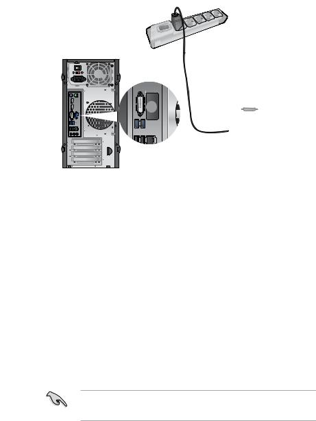
Setting up your computer
This section guides you through connecting the main hardware devices, such as the external monitor, keyboard, mouse, and power cord, to your computer.
Using the onboard display output ports
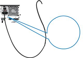
Connect your monitor to the onboard display output port.
To connect an external monitor using the onboard display output ports:
1.Connect a VGA monitor to the VGA port, or a DVI-D monitor to the DVI-D port, or an HDMI monitor to the HDMI port on the rear panel of your computer.
2.Plug the monitor to a power source.
BM6675(MD750)
ENGLISH
|
|
|
|
|
|
|
|
|
|
|
|
|
|
|
|
|
|
|
|
|
|
|
|
|
|
|
|
|
|
|
|
|
|
|
|
|
|
|
|
|
|
|
|
|
|
|
|
|
|
|
|
|
|
|
|
|
|
|
|
|
|
|
|
|
|
|
|
|
|
|
|
|
|
|
|
|
|
|
|
|
|
|
|
|
|
|
|
|
|
|
|
|
|
|
|
|
|
|
|
|
|
|
|
|
|
|
|
|
|
|
|
|
|
|
|
|
|
|
|
|
|
|
|
|
|
|
|
|
|
|
|
|
|
|
|
|
|
|
|
|
|
|
|
|
|
|
|
|
|
|
|
|
|
|
|
|
|
|
|
|
|
|
|
|
|
|
|
|
|
|
|
|
|
|
|
|
|
|
|
|
|
|
|
|
|
|
|
|
|
|
|
|
|
|
|
|
|
|
|
|
|
|
|
|
|
|
|
|
|
|
|
|
|
|
|
|
|
|
|
|
|
|
|
|
|
|
|
|
|
|
|
|
|
|
|
|
|
|
|
|
|
|
|
|
|
|
|
|
|
|
|
|
|
|
|
|
|
|
|
|
|
|
|
|
|
|
|
|
|
|
|
|
|
|
|
|
|
|
|
|
|
|
|
|
|
|
|
|
|
|
|
|
|
|
|
|
|
|
|
|
|
|
|
ASUS BM6675(MD750), BM6875, and BP6375(SD750) |
21 |
|||||||||||||||||
BM6875
ENGLISH
BP6375(SD750)
If your computer comes with an ASUS Graphics Card, the graphics card is set as the primary display device in the BIOS. Hence, connect your monitor to a display output port on the graphics card.
22 |
Chapter 1: Getting started |
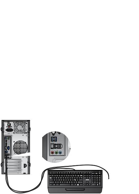
Connecting a USB keyboard and a USB mouse
Connect a USB keyboard and a USB mouse to the USB ports on the rear panel of your computer.
BM6675(MD750) |
BM6875 |
ENGLISH
|
|
|
|
|
|
|
|
|
|
|
|
|
|
|
|
|
|
|
|
|
|
|
|
|
|
|
|
|
|
ASUS BM6675(MD750), BM6875, and BP6375(SD750) |
23 |
||||
BP6375(SD750)
ENGLISH
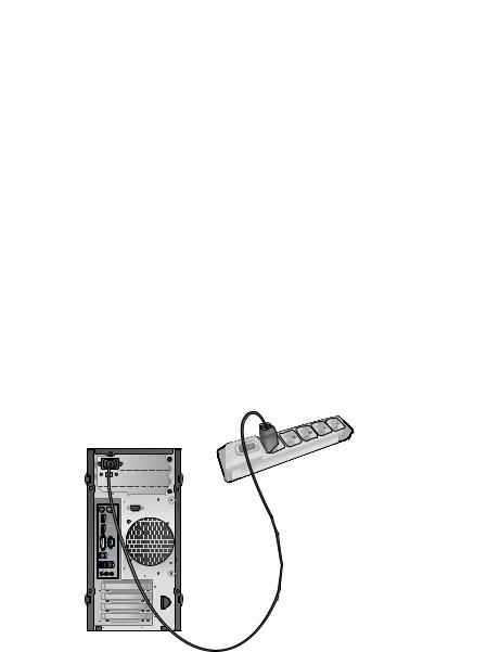
Connecting the power cord
Connect one end of the power cord to the power connector on the rear panel of your computer and the other end to a power source.
BM6675(MD750)
24 |
Chapter 1: Getting started |
BM6875 


 ENGLISH
BP6375(SD750)
ASUS BM6675(MD750), BM6875, and BP6375(SD750) |
25 |
ENGLISH
Turning your computer ON/OFF
This section describes how to turn on/off your computer after setting up your computer.
Turning your computer ON
To turn your computer ON:
1.Turn your monitor ON.
2.Turn on the power switch. (BM6875 only)
3.Press the power button on your computer.
Power button 

Power button
BM6875
BM6675(MD750)
Power button 


BP6375(SD750)
4.Wait until the operating system loads automatically.
Turning your computer OFF
To turn your computer OFF on Windows® 7:
1.Close all running applications.
2.Click  on the Windows® desktop.
3.Click  to shut down the operating system.
For details on shutting down your Desktop PC on Windows® 8, refer to the section Turning your Desktop PC OFF in Chapter 3.
26 |
Chapter 1: Getting started |

Chapter 2
Using Windows® 7
Starting for the first time
When you start your computer for the first time, a series of screens appear to guide you in configuring the basic settings of your Windows® 7 operating system.
To start for the first time:
1.Turn your computer on. Wait for a few minutes until the Set Up Windows screen appears.
2.From dropdown list, select your language, then click Next.
3.From the dropdown lists, select your Country or region, Time and currency, and
Keyboard layout, then click Next.
4.Key in uniques names for the user name and computer name, then click Next.
5.Key in the necessary information to set up your password, then click Next. You may also click Next to skip this step without entering any information.
If you want to set up a password for your account later, refer to the section Setting up a user account and password in this chapter.
6.Carefully read the license terms. Tick I accept the license terms and click Next.
7.Select Use recommended settings or Install important updates only to set up the security settings for your computer. To skip this step, select Ask me later.
8.Review your date and time settings. Click Next. The system loads the new settings and restarts. You may now start using your computer.
ENGLISH
ASUS BM6675(MD750), BM6875, and BP6375(SD750) |
27 |
ENGLISH
Using Windows® 7 desktop
Click the Start icon  > Help and Support to obtain more information about Windows® 7.
Using the Start menu
The Start menu gives you access to programs, utilities, and other useful items on your computer. It also provides you with more information about Windows 7 through its Help and Support feature.
Launching items from the Start menu
To launch items from the Start menu:
1.From the Windows® taskbar, click the Start icon  .
.
2.From the Start menu, select the item that you want to launch.
You may pin programs that you want constantly displayed on the Start menu. For more details, refer to the section Pinning programs on the Start menu or taskbar on this chapter.
Using the Getting Started item
The Getting Started item on the Start menu contains information about some basic tasks such as personalizing Windows®, adding new users, and transferring files to help you to familiarize yourself with using Windows® 7.
To use the Getting Started item:
1.From the Windows® taskbar, click the Start icon  to launch the Start menu.
2.Select Getting Started. The list of available tasks appears.
3.Select the task that you want to do.
Using the taskbar
The taskbar allows you to launch and manage programs or items installed on your computer.
Launching a program from the taskbar
To launch a program from the taskbar:
•From the Windows® taskbar, click an icon to launch it. Click the icon again to hide the program.
You may pin programs that you want constantly displayed on the taskbar. For more details, refer to the section Pinning programs on the Start menu or taskbar on this chapter.
28 |
Chapter 2: Using Windows® 7 |

Pinning items on the jumplists
When you right-click an icon on the taskbar, a jumplist launches to provide you with quickaccess to the program’s or item’s related links.You may pin items on the jumplist such as favorite websites, often-visited folders or drives, or recently played media files.
To pin items to the jumplist:
1.From the taskbar, right-click an icon.
2.From the jumplist, right-click the item that you want to pin, then select Pin to this list.
Unpinning items from the jumplist
To unpin items from the jumplist:
1.From the taskbar, right-click an icon.
2.From the jumplist, right-click the item that you want to remove from the jumplist, then select Unpin from this list.
Pinning programs on the Start menu or taskbar
To pin programs on the Start menu or taskbar:
1.From the Windows® taskbar, click the Start icon  to launch the Start menu.
2.Right-click the item that you want to pin on the Start menu or taskbar.
3.Select Pin to Taskbar or Pin to Start menu.
You may also right-click on the icon of a running program on the taskbar, then select Pin this program to taskbar.
Unpinning programs from the Start menu
To unpin programs from the Start menu:
1.From the Windows® taskbar, click the Start icon  to launch the Start menu.
2.From the Start menu, right-click the program that you want to unpin, then select
Remove from this list.
Unpinning programs from the taskbar
To unpin programs from the taskbar:
1.From the taskbar, right-click the program that you want to remove from the taskbar, then select Unpin this program from taskbar.
ENGLISH
ASUS BM6675(MD750), BM6875, and BP6375(SD750) |
29 |

ENGLISH
Using the notification area
By default, the notification area shows these three icons:
Action Center notification
Click this icon to display all the alert messages/notifications and launch the Windows®
Action Center.
Network connection
This icon displays the connection status and signal strength of the wired or wireless network connection.
Volume
Click this icon to adjust the volume.
Displaying an alert notification
To display an alert notification:
•Click the Notification icon  , then click the message to open it.
For more details, refer to the section Using Windows® Action Center in this chapter.
Customizing icons and notifications
You may choose to display or hide the icons and notifications on the taskbar or on the notification area.
To customize icons and notifications:
1.From the notification area, click on the arrow icon  .
.
2.Click Customize.
3.From the dropdown list, select the behaviors for the icons or items that you want to customize.
Managing your files and folders
Using Windows® Explorer
Windows® Explorer allows you to view, manage, and organize your files and folders.
Launching Windows® Explorer
To launch Windows Explorer:
1.From the Windows® taskbar, click the Start icon  to launch the Start menu.
2.Click Computer to launch Windows Explorer.
30 |
Chapter 2: Using Windows® 7 |
 Loading...