


Copyright Notice:
No part of this installation guide may be reproduced, transcribed, transmitted, or translated in any language, in any form or by any means, except duplication of documentation by the purchaser for backup purpose, without written consent of ASRock Inc.
Products and corporate names appearing in this guide may or may not be registered trademarks or copyrights of their respective companies, and are used only for identification or explanation and to the owners’ benefit, without intent to infringe.
Disclaimer:
Specifications and information contained in this guide are furnished for informational use only and subject to change without notice, and should not be constructed as a commitment by ASRock. ASRock assumes no responsibility for any errors or omissions that may appear in this guide.
With respect to the contents of this guide, ASRock does not provide warranty of any kind, either expressed or implied, including but not limited to the implied warranties or conditions of merchantability or fitness for a particular purpose. In no event shall ASRock, its directors, officers, employees, or agents be liable for any indirect, special, incidental, or consequential damages (including damages for loss of profits, loss of business, loss of data, interruption of business and the like), even if ASRock has been advised of the possibility of such damages arising from any defect or error in the guide or product.
This device complies with Part 15 of the FCC Rules. Operation is subject to the following two conditions:
(1)this device may not cause harmful interference, and
(2)this device must accept any interference received, including interference that may cause undesired operation.
CALIFORNIA, USA ONLY
The Lithium battery adopted on this motherboard contains Perchlorate, a toxic substance controlled in Perchlorate Best Management Practices (BMP) regulations passed by the California Legislature. When you discard the Lithium battery in California, USA, please follow the related regulations in advance.
“Perchlorate Material-special handling may apply, see www.dtsc.ca.gov/hazardouswaste/perchlorate”
ASRock Website: http://www.asrock.com
Published February 2010
Copyright©2010 ASRock INC. All rights reserved.
1
English
ASRock 770 Extreme3 Motherboard

Motherboard Layout
English
2
1 |
PS2_USB_PW1 Jumper |
21 |
USB 2.0 Header (USB8_9, Blue) |
2 |
CPU Fan Connector (CPU_FAN1) |
22 |
USB 2.0 Header (USB6_7, Blue) |
3 |
ATX 12V Power Connector (ATX12V1) |
23 |
USB 2.0 Header (USB10_11, Blue) |
4 |
AM3 CPU Socket |
24 |
System Panel Header (PANEL1, White) |
5 |
CPU Heatsink Retention Module |
25 |
SPI Flash Memory (8Mb) |
6 |
2 x 240-pin DDR3 DIMM Slots |
26 |
Infrared Module Header (IR1) |
|
(Dual Channel A: DDR3_A1, DDR3_B1; Blue) |
27 |
Floppy Connector (FLOPPY1) |
7 |
2 x 240-pin DDR3 DIMM Slots |
28 |
Serial Port Connector (COM1) |
|
(Dual Channel B: DDR3_A2, DDR3_B2; White) |
29 |
Front Panel Audio Header |
8 |
ATX Power Connector (ATXPWR1) |
|
(HD_AUDIO1, White) |
9 |
Primary IDE Connector (IDE1, Blue) |
30 |
Internal Audio Connector: CD1 (Black) |
10 |
SATA3 Connector (SATA3_2, White) |
31 |
HDMI_SPDIF Header |
11 |
SATA3 Connector (SATA3_1, White) |
|
(HDMI_SPDIF1, White) |
12 |
Southbridge Controller |
32 |
PCI Slots (PCI1- 3) |
13 |
USB_PW3 Jumper |
33 |
PCI Express 2.0 x1 Slot (PCIE3; White) |
14 |
SATAII Connector (SATAII_1, Blue) |
34 |
Clear CMOS Jumper (CLRCMOS1) |
15 |
SATAII Connector (SATAII_3, Blue) |
35 |
PCI Express 2.0 x16 Slot (PCIE2; Blue) |
16 |
SATAII Connector (SATAII_4, Blue) |
36 |
PCI Express 2.0 x1 Slot (PCIE1; White) |
17 |
Chassis Speaker Header (SPEAKER 1, White) |
37 |
Power Fan Connector (PWR_FAN1) |
18 |
SATAII Connector (SATAII_2, Blue) |
38 |
Northbridge Controller |
19 |
Power LED Header (PLED1) |
39 |
USB_PW2 Jumper |
20 |
Chassis Fan Connector (CHA_FAN1) |
|
|
ASRock 770 Extreme3 Motherboard
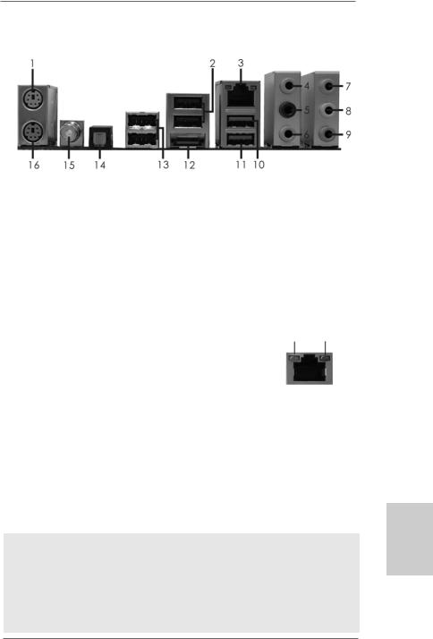
I/O Panel
1 |
PS/2 Mouse Port (Green) |
9 |
Microphone (Pink) |
2 |
USB 2.0 Ports (USB23) |
10 |
USB 2.0 Port |
* 3 |
LAN RJ-45 Port |
11 |
USB 3.0 Port |
4 |
Side Speaker (Gray) |
12 |
eSATAII Connector |
5 |
Rear Speaker (Black) |
13 |
USB 2.0 Ports (USB45) |
6 |
Central / Bass (Orange) |
14 |
Optical SPDIF Out Port |
7 |
Line In (Light Blue) |
15 |
Coaxial SPDIF Out Port |
** 8 |
Front Speaker (Lime) |
16 |
PS/2 Keyboard Port (Purple) |
*There are two LED next to the LAN port. Please refer to the table below for the LAN port LED indications.
LAN Port LED Indications
Activity/Link LED |
|
SPEED LED |
ACT/LINK |
SPEED |
|||
|
LED |
LED |
|||||
Status |
Description |
|
Status |
|
Description |
||
|
|
|
|
||||
Off |
No Link |
|
Off |
|
10Mbps connection |
|
|
Blinking |
Data Activity |
|
Orange |
|
100Mbps connection |
|
|
|
|
|
|
|
|
|
|
On |
Link |
|
Green |
|
1Gbps connection |
LAN Port |
|
|
|
|
|
|
|
||
**If you use 2-channel speaker, please connect the speaker’s plug into “Front Speaker Jack”. See the table below for connection details in accordance with the type of speaker you use.
TABLE for Audio Output Connection
Audio Output Channels |
Front Speaker |
Rear Speaker |
Central / Bass |
Side Speaker |
|
(No. 8) |
(No. 5) |
(No. 6) |
(No. 4) |
2 |
V |
-- |
-- |
-- |
4 |
V |
V |
-- |
-- |
6 |
V |
V |
V |
-- |
8 |
V |
V |
V |
V |
To enable Multi-Streaming function, you need to connect a front panel audio cable to the front panel audio header. After restarting your computer, you will find “Mixer” tool on your system. Please select “Mixer ToolBox”  , click “Enable playback multi-streaming”, and click
“ok”. Choose “2CH”, “4CH”, “6CH”, or “8CH” and then you are allowed to select “Realtek HDA Primary output” to use Rear Speaker, Central/Bass, and Front Speaker, or select “Realtek HDA Audio 2nd output” to use front panel audio.
3
English
ASRock 770 Extreme3 Motherboard

1. Introduction
Thank you for purchasing ASRock 770 Extreme3 motherboard, a reliable motherboard produced under ASRock’s consistently stringent quality control. It delivers excellent performance with robust design conforming to ASRock’s commitment to quality and endurance.
In this manual, chapter 1 and 2 contain introduction of the motherboard and step-by-step guide to the hardware installation. Chapter 3 and 4 contain the configuration guide to BIOS setup and information of the Support CD.
Because the motherboard specifications and the BIOS software might be updated, the content of this manual will be subject to change without notice. In case any modifications of this manual occur, the updated version will be available on ASRock website without further notice. You may find the latest VGA cards and CPU support lists on ASRock website as well. ASRock website http://www.asrock.com
If you require technical support related to this motherboard, please visit our website for specific information about the model you are using. www.asrock.com/support/index.asp
1.1Package Contents
ASRock 770 Extreme3 Motherboard
(ATX Form Factor: 12.0-in x 8.2-in, 30.5 cm x 20.8 cm) ASRock 770 Extreme3 Quick Installation Guide
ASRock 770 Extreme3 Support CD
1 x Ultra ATA 66/100/133 IDE Ribbon Cable (80-conductor) 2 x Serial ATA (SATA) Data Cables (Optional)
1 x Serial ATA (SATA) HDD Power Cable (Optional)
1 x I/O Panel Shield
hsilgnE
4
ASRock 770 Extreme3 Motherboard

1.2Specifications
Platform |
- ATX Form Factor: 12.0-in x 8.2-in, 30.5 cm x 20.8 cm |
|
- All Solid Capacitor design (100% Japan-made high-quality |
|
Conductive Polymer Capacitors) |
|
|
CPU |
- Support for Socket AM3 processors: AMD PhenomTM II X4 / |
|
X3 / X2 (except 920 / 940) / Athlon II X4 / X3 / X2 / Sempron |
|
processors |
|
- Supports CPU up to 140W |
|
- Supports AMD OverDriveTM with ACC feature (Advanced |
|
Clock Calibration) |
|
- AMD LIVE!TM Ready |
|
- Supports AMD’s Cool ‘n’ QuietTM Technology |
|
- FSB 2600 MHz (5.2 GT/s) |
|
- Supports Untied Overclocking Technology (see CAUTION 1) |
|
- Supports Hyper-Transport 3.0 (HT 3.0) Technology |
Chipset |
- Northbridge: AMD 770 |
|
- Southbridge: AMD SB710 |
Memory |
- Dual Channel DDR3 Memory Technology (see CAUTION 2) |
|
- 4 x DDR3 DIMM slots |
|
- Support DDR3 1600/1333/1066/800 non-ECC, un-buffered |
|
memory (see CAUTION 3) |
|
- Max. capacity of system memory: 16GB (see CAUTION 4) |
Expansion Slot |
- 1 x PCI Express 2.0 x16 slot (blue @ x16 mode) |
|
- 2 x PCI Express 2.0 x1 slots |
|
- 3 x PCI slots |
Audio |
- 7.1 CH HD Audio with Content Protection |
|
(Realtek ALC892 Audio Codec) |
|
- Premium Blu-ray audio support |
LAN |
- PCIE x1 Gigabit LAN 10/100/1000 Mb/s |
|
- Realtek RTL8111DL |
|
- Supports Wake-On-LAN |
Rear Panel I/O |
I/O Panel |
|
- 1 x PS/2 Mouse Port |
|
- 1 x PS/2 Keyboard Port |
|
- 1 x Coaxial SPDIF Out Port |
|
- 1 x Optical SPDIF Out Port |
|
- 5 x Ready-to-Use USB 2.0 Ports |
|
- 1 x eSATAII Connector |
|
- 1 x Ready-to-Use USB 3.0 Port |
|
- 1 x RJ-45 LAN Port with LED (ACT/LINK LED and SPEED LED) |
|
|
|
|
English
5
ASRock 770 Extreme3 Motherboard

hsilgnE
6
|
|
- HD Audio Jack: Side Speaker/Rear Speaker/Central/Bass/ |
|
|
Line in/Front Speaker/Microphone (see CAUTION 5) |
|
SATA3 |
- 2 x SATA3 6.0Gb/s connectors by Marvell SE9123/9120, |
|
|
support NCQ, AHCI and “Hot Plug” functions |
|
USB 3.0 |
- 1 x USB 3.0 port by Fresco FL1000G, support USB 3.0 up to |
|
|
5Gb/s |
|
Connector |
- 4 x SATAII 3.0Gb/s connectors, support RAID (RAID 0, |
|
|
RAID 1, RAID 10 and JBOD), NCQ, AHCI and “Hot Plug” |
|
|
functions |
|
|
- 2 x SATA3 6.0Gb/s connectors |
|
|
- 1 x ATA133 IDE connector (supports 2 x IDE devices) |
|
|
- 1 x Floppy connector |
|
|
- 1 x IR header |
|
|
- 1 x COM port header |
|
|
- 1 x HDMI_SPDIF header |
|
|
- 1 x Power LED header |
|
|
- CPU/Chassis/Power FAN connector |
|
|
- 24 pin ATX power connector |
|
|
- 8 pin 12V power connector |
|
|
- CD in header |
|
|
- Front panel audio connector |
|
|
- 3 x USB 2.0 headers (support 6 USB 2.0 ports) |
|
|
(see CAUTION 6) |
|
BIOS Feature |
- 8Mb AMI BIOS |
|
|
- AMI Legal BIOS |
|
|
- Supports “Plug and Play” |
|
|
- ACPI 1.1 Compliance Wake Up Events |
|
|
- Supports jumperfree |
|
|
- SMBIOS 2.3.1 Support |
|
|
- CPU VID Voltage Multi-adjustment |
|
Support CD |
- Drivers, Utilities, AntiVirus Software (Trial Version), AMD |
|
|
OverDriveTM Utility, ASRock Software Suite (CyberLink DVD |
|
|
Suite and Creative Sound Blaster X-Fi MB) (OEM and Trial |
|
|
Version) |
|
Unique Feature |
- ASRock OC Tuner (see CAUTION 7) |
|
|
- Intelligent Energy Saver (see CAUTION 8) |
|
|
- Instant Boot |
|
|
- ASRock Instant Flash (see CAUTION 9) |
|
|
- ASRock OC DNA (see CAUTION 10) |
|
|
- Hybrid Booster: |
|
|
- CPU Frequency Stepless Control (see CAUTION 11) |
|
|
- ASRock U-COP (see CAUTION 12) |
|
|
|
ASRock 770 Extreme3 Motherboard

|
- Boot Failure Guard (B.F.G.) |
Hardware |
- CPU Temperature Sensing |
Monitor |
- Chassis Temperature Sensing |
|
- CPU/Chassis/Power Fan Tachometer |
|
- CPU Quiet Fan |
|
- Voltage Monitoring: +12V, +5V, +3.3V, Vcore |
OS |
- Microsoft® Windows® 7 / 7 64-bit / VistaTM / VistaTM 64-bit |
|
/ XP / XP Media Center / XP 64-bit compliant |
Certifications |
- FCC, CE, WHQL |
|
- ErP/EuP Ready (ErP/EuP ready power supply is required) |
|
(see CAUTION 13) |
* For detailed product information, please visit our website: http://www.asrock.com
WARNING
Please realize that there is a certain risk involved with overclocking, including adjusting the setting in the BIOS, applying Untied Overclocking Technology, or using the thirdparty overclocking tools. Overclocking may affect your system stability, or even cause damage to the components and devices of your system. It should be done at your own risk and expense. We are not responsible for possible damage caused by overclocking.
CAUTION!
1.This motherboard supports Untied Overclocking Technology. Please read “Untied Overclocking Technology” on page 21 for details.
2.This motherboard supports Dual Channel Memory Technology. Before you implement Dual Channel Memory Technology, make sure to read the installation guide of memory modules on page 11 for proper installation.
3.Whether 1600MHz memory speed is supported depends on the AM3 CPU you adopt. If you want to adopt DDR3 1600 memory module on this motherboard, please refer to the memory support list on our website for the compatible memory modules.
ASRock website http://www.asrock.com
4.Due to the operating system limitation, the actual memory size may be less than 4GB for the reservation for system usage under Windows® 7 / VistaTM / XP. For Windows® OS with 64-bit CPU, there is no such limitation.
5.For microphone input, this motherboard supports both stereo and mono modes. For audio output, this motherboard supports 2-channel, 4-channel, 6-channel, and 8-channel modes. Please check the table on page 3 for proper connection.
6.Power Management for USB 2.0 works fine under Microsoft® Windows® 7 64-bit / 7 / VistaTM 64-bit / VistaTM / XP 64-bit / XP SP1 or SP2.
7.It is a user-friendly ASRock overclocking tool which allows you to surveil your system by hardware monitor function and overclock your hardware devices to get the best system performance under Windows® environment. Please visit our website for the operation procedures of ASRock OC Tuner. ASRock website: http://www.asrock.com
7
English
ASRock 770 Extreme3 Motherboard

hsilgnE
8
8.Featuring an advanced proprietary hardware and software design, Intelligent Energy Saver is a revolutionary technology that delivers unparalleled power savings. The voltage regulator can reduce the number of output phases to improve efficiency when the CPU cores are idle. In other words, it is able to provide exceptional power saving and improve power efficiency without sacrificing computing performance. To use Intelligent Energy Saver function, please enable Cool ‘n’ Quiet option in the BIOS setup in advance. Please visit our website for the operation procedures of Intelligent Energy Saver.
ASRock website: http://www.asrock.com
9.ASRock Instant Flash is a BIOS flash utility embedded in Flash ROM. This convenient BIOS update tool allows you to update system BIOS without entering operating systems first like MS-DOS or Windows®. With this utility, you can press <F6> key during the POST or press <F2> key to BIOS setup menu to access ASRock Instant Flash. Just launch this tool and save the new BIOS file to your USB flash drive, floppy disk or hard drive, then you can update your BIOS only in a few clicks without preparing an additional floppy diskette or other complicated flash utility. Please be noted that the USB flash drive or hard drive must use FAT32/16/12 file system.
10.The software name itself – OC DNA literally tells you what it is capable of. OC DNA, an exclusive utility developed by ASRock, provides a convenient way for the user to record the OC settings and share with others. It helps you to save your overclocking record under the operating system and simplifies the complicated recording process of overclocking settings. With OC DNA, you can save your OC settings as a profile and share with your friends! Your friends then can load the OC profile to their own system to get the same OC settings as yours! Please be noticed that the OC profile can only be shared and worked on the same motherboard.
11.Although this motherboard offers stepless control, it is not recommended to perform over-clocking. Frequencies other than the recommended CPU bus frequencies may cause the instability of the system or damage the CPU.
12.While CPU overheat is detected, the system will automatically shutdown. Before you resume the system, please check if the CPU fan on the motherboard functions properly and unplug the power cord, then plug it back again. To improve heat dissipation, remember to spray thermal grease between the CPU and the heatsink when you install the PC system.
13.EuP, stands for Energy Using Product, was a provision regulated by European Union to define the power consumption for the completed system. According to EuP, the total AC power of the completed system shall be under 1.00W in off mode condition. To meet EuP standard, an EuP ready motherboard and an EuP ready power supply are required. According to Intel’s suggestion, the EuP ready power supply must meet the standard of 5v standby power efficiency is higher than 50% under 100 mA current consumption. For EuP ready power supply selection, we recommend you checking with the power supply manufacturer for more details.
ASRock 770 Extreme3 Motherboard

2. Installation
This is an ATX form factor (12.0-in x 8.2-in, 30.5 cm x 20.8 cm) motherboard.
Before you install the motherboard, study the configuration of your chassis to ensure that the motherboard fits into it.
Pre-installation Precautions
Take note of the following precautions before you install motherboard components or change any motherboard settings.
Before you install or remove any component, ensure that the power is switched off or the power cord is detached from the power supply. Failure to do so may cause severe damage to the motherboard, peripherals, and/or components.
1.Unplug the power cord from the wall socket before touching any component.
2.To avoid damaging the motherboard components due to static electricity, NEVER place your motherboard directly on the carpet or the like. Also remember to use a grounded wrist strap or touch a safety grounded object before you handle components.
3.Hold components by the edges and do not touch the ICs.
4.Whenever you uninstall any component, place it on a grounded antistatic pad or in the bag that comes with the component.
5.When placing screws into the screw holes to secure the motherboard to the chassis, please do not over-tighten the screws! Doing so may damage the motherboard.
English
9
ASRock 770 Extreme3 Motherboard
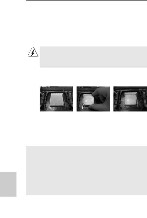
2.1CPU Installation
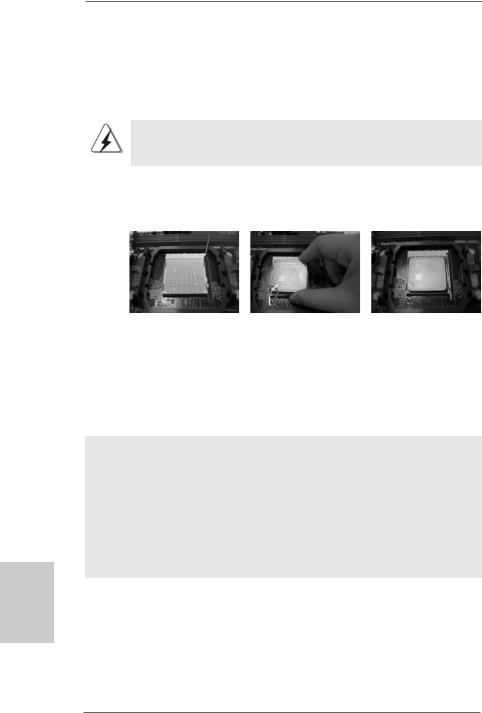
Step 1. Unlock the socket by lifting the lever up to a 90o angle.
Step 2. Position the CPU directly above the socket such that the CPU corner with the golden triangle matches the socket corner with a small triangle.
Step 3. Carefully insert the CPU into the socket until it fits in place.
The CPU fits only in one correct orientation. DO NOT force the CPU into the socket to avoid bending of the pins.
Step 4. When the CPU is in place, press it firmly on the socket while you push down the socket lever to secure the CPU. The lever clicks on the side tab to indicate that it is locked.
Lever 90° Up |
|
|
|
CPU Golden Triangle |
|
|
Socker Corner Small Triangle |
|
STEP 1: |
STEP 2 / STEP 3: |
STEP 4: |
Lift Up The Socket Lever |
Match The CPU Golden Triangle |
Push Down And Lock |
|
To The Socket Corner Small |
The Socket Lever |
|
Triangle |
|
2.2 Installation of CPU Fan and Heatsink
After you install the CPU into this motherboard, it is necessary to install a larger heatsink and cooling fan to dissipate heat. You also need to spray thermal grease between the CPU and the heatsink to improve heat dissipation. Make sure that the CPU and the heatsink are securely fastened and in good contact with each other. Then connect the CPU fan to the CPU FAN connector (CPU_FAN1, see Page 2, No. 2). For proper installation, please kindly refer to the instruction manuals of the CPU fan and the heatsink.
English
1 0
ASRock 770 Extreme3 Motherboard
2.3 Installation of Memory Modules (DIMM)
This motherboard provides four 240-pin DDR3 (Double Data Rate 3) DIMM slots, and supports Dual Channel Memory Technology. For dual channel configuration, you always need to install identical (the same brand, speed, size and chiptype) DDR3 DIMM pair in the slots of the same color. In other words, you have to install identical DDR3 DIMM pair in Dual Channel A (DDR3_A1 and DDR3_B1; Blue slots; see p.2 No.6) or identical DDR3 DIMM pair in Dual Channel B (DDR3_A2 and DDR3_B2; White slots; see p.2 No.7), so that Dual Channel Memory Technology can be activated. This motherboard also allows you to install four DDR3 DIMMs for dual channel configuration, and please install identical DDR3 DIMMs in all four slots. You may refer to the Dual Channel Memory Configuration Table below.
Dual Channel Memory Configurations
|
DDR3_A1 |
DDR3_B1 |
DDR3_A2 |
DDR3_B2 |
|
(Blue Slot) |
(Blue Slot) |
(White Slot) |
(White Slot) |
(1) |
Populated |
Populated |
- |
- |
(2) |
- |
- |
Populated |
Populated |
(3)* |
Populated |
Populated |
Populated |
Populated |
* For the configuration (3), please install identical DDR3 DIMMs in all four slots.
1.If you want to install two memory modules, for optimal compatibility and reliability, it is recommended to install them in the slots of the same color. In other words, install them either in the set of blue slots (DDR3_A1 and DDR3_B1), or in the set of white slots (DDR3_A2 and DDR3_B2).
2.If only one memory module or three memory modules are installed in the DDR3 DIMM slots on this motherboard, it is unable to activate the Dual Channel Memory Technology.
3.If a pair of memory modules is NOT installed in the same Dual Channel, for example, installing a pair of memory modules in DDR3_A1 and DDR3_A2, it is unable to activate the Dual Channel Memory Technology .
4.It is not allowed to install a DDR or DDR2 memory module into DDR3 slot; otherwise, this motherboard and DIMM may be damaged.
5.If you adopt DDR3 1600 memory modules on this motherboard, it is recommended to install them on DDR3_A2 and DDR3_B2 slots.
1 1
English
ASRock 770 Extreme3 Motherboard

Installing a DIMM
Please make sure to disconnect power supply before adding or removing DIMMs or the system components.
Step 1. Unlock a DIMM slot by pressing the retaining clips outward.
Step 2. Align a DIMM on the slot such that the notch on the DIMM matches the break on the slot.
The DIMM only fits in one correct orientation. It will cause permanent damage to the motherboard and the DIMM if you force the DIMM into the slot at incorrect orientation.
Step 3. Firmly insert the DIMM into the slot until the retaining clips at both ends fully snap back in place and the DIMM is properly seated.
English
1 2
ASRock 770 Extreme3 Motherboard

2.4 Expansion Slots (PCI and PCI Express Slots)
There are 3 PCI slots and 3 PCI Express slots on this motherboard.
PCI Slots: PCI slots are used to install expansion cards that have the 32-bit PCI interface.
PCIE Slots:
PCIE1 / PCIE3 (PCIE x1 slot; White) is used for PCI Express cards with x1 lane width cards, such as Gigabit LAN card and SATA2 card. PCIE2 (PCIE x16 slot; Blue) is used for PCI Express x16 lane width graphics cards.
Installing an expansion card
Step 1. Before installing the expansion card, please make sure that the power supply is switched off or the power cord is unplugged. Please read the documentation of the expansion card and make necessary hardware settings for the card before you start the installation.
Step 2. Remove the system unit cover (if your motherboard is already installed in a chassis).
Step 3. Remove the bracket facing the slot that you intend to use. Keep the screws for later use.
Step 4. Align the card connector with the slot and press firmly until the card is completely seated on the slot.
Step 5. Fasten the card to the chassis with screws. Step 6. Replace the system cover.
English
1 3
ASRock 770 Extreme3 Motherboard
English
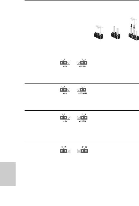
2.5Jumpers Setup
The illustration shows how jumpers are setup. When the jumper cap is placed on pins, the jumper is “Short”. If no jumper cap is placed on pins, the jumper is “Open”. The illustration shows a 3-pin jumper whose pin1
and pin2 are “Short” when jumper cap is Short Open placed on these 2 pins.
Jumper |
Setting |
PS2_USB_PW1 |
Short pin2, pin3 to enable |
(see p.2, No. 1) |
+5VSB (standby) for PS/2 or |
|
USB wake up events. |
Note: To select +5VSB, it requires 2 Amp and higher standby current provided by power supply.
USB_PW2 |
Short pin2, pin3 to enable |
(see p.2, No. 39) |
+5V_DUAL for USB45 wake |
|
up events. |
Note: To select +5V_DUAL, it requires 2 Amp and higher standby current provided by power supply.
USB_PW3 |
Short pin2, pin3 to enable |
(see p.2, No. 13) |
+5VSB (standby) for |
|
USB6_7/8_9/10_11 wake up |
|
events. |
Note: To select +5VSB, it requires 2 Amp and higher standby current provided by power supply.
Clear CMOS Jumper
(CLRCMOS1)
(see p.2, No. 34) |
Default |
Clear CMOS |
|
Note: CLRCMOS1 allows you to clear the data in CMOS. The data in CMOS includes system setup information such as system password, date, time, and system setup parameters. To clear and reset the system parameters to default setup, please turn off the computer and unplug the power cord from the power supply. After waiting for 15 seconds, use a jumper cap to short pin2 and pin3 on CLRCMOS1 for 5 seconds. However, please do not clear the CMOS right after you update the BIOS. If you need to clear the CMOS when you just finish updating the BIOS, you must boot up the system first, and then shut it down before you do the clear-CMOS action.
1 4
ASRock 770 Extreme3 Motherboard
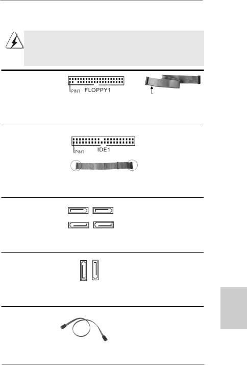
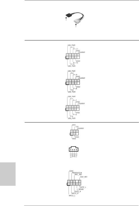
2.6 Onboard Headers and Connectors
Onboard headers and connectors are NOT jumpers. Do NOT place jumper caps over these headers and connectors. Placing jumper caps over the headers and connectors will cause permanent damage of the motherboard!
•
Floppy Connector
(33-pin FLOPPY1)
(see p.2 No. 27)
the red-striped side to Pin1
Note: Make sure the red-striped side of the cable is plugged into Pin1 side of the connector.
Primary IDE connector (Blue)
(39-pin IDE1, see p.2 No. 9)
connect the blue end |
connect the black end |
to the motherboard |
to the IDE devices |
80-conductor ATA 66/100/133 cable
Note: Please refer to the instruction of your IDE device vendor for the details.
Serial ATAII Connectors
(SATAII_1: see p.2,No. 14)
SATAII_1 SATAII_3
(SATAII_2: see p.2,No. 18)
(SATAII_3: see p.2,No. 15)
SATAII_2 SATAII_4
(SATAII_4: see p.2,No. 16)
These four Serial ATAII (SATAII) connectors support SATAII
or SATA hard disk for internal storage devices. The current SATAII interface allows up to 3.0 Gb/s data transfer rate.
Serial ATA3 Connectors
(SATA3_1: see p.2,No. 11)
(SATA3_2: see p.2,No. 10)
SATA3 2 |
SATA3 1 |
These two Serial ATA3 (SATA3) connectors support SATA data cables for internal storage devices. The current SATA3 interface allows up to 6.0 Gb/s data transfer rate.
Serial ATA (SATA) |
Either end of the SATA data cable |
Data Cable |
can be connected to the SATA / |
(Optional) |
SATAII / SATA3 hard disk or the |
|
SATAII / SATA3 connector on this |
|
motherboard. |
1 5
English
ASRock 770 Extreme3 Motherboard
Serial ATA (SATA)
Power Cable
(Optional) |
connect to the SATA |
|
HDD power connector |
connect to the powersupply
Please connect the black end of SATA power cable to the power connector on each drive. Then connect the white end of SATA power cable to the power connector of the power supply.
USB 2.0 Headers |
Besides five default USB 2.0 |
(9-pin USB10_11) |
ports on the I/O panel, there are |
(see p.2 No. 23) |
three USB 2.0 headers on this |
|
motherboard. Each USB 2.0 |
|
header can support two USB |
|
2.0 ports. |
(9-pin USB8_9) |
|
(see p.2 No. 21) |
|
(9-pin USB6_7)
(see p.2 No. 22)
English
Infrared Module Header |
|
This header supports an |
(5-pin IR1) |
|
optional wireless transmitting |
(see p.2 No. 26) |
|
and receiving infrared module. |
|
|
|
Internal Audio Connectors |
|
This connector allows you |
(4-pin CD1) |
CD1 |
to receive stereo audio input |
(CD1: see p.2 No. 30) |
|
from sound sources such as |
|
|
a CD-ROM, DVD-ROM, TV |
|
|
tuner card, or MPEG card. |
|
|
|
Front Panel Audio Header |
|
This is an interface for the front |
(9-pin HD_AUDIO1) |
|
panel audio cable that allows |
(see p.2, No. 29) |
|
convenient connection and |
|
|
control of audio devices. |
1 6
ASRock 770 Extreme3 Motherboard
1.High Definition Audio supports Jack Sensing, but the panel wire on the chassis must support HDA to function correctly. Please follow the instruction in our manual and chassis manual to install your system.
2.If you use AC’97 audio panel, please install it to the front panel audio header as below:
A.Connect Mic_IN (MIC) to MIC2_L.
B.Connect Audio_R (RIN) to OUT2_R and Audio_L (LIN) to OUT2_L.
C.Connect Ground (GND) to Ground (GND).
D.MIC_RET and OUT_RET are for HD audio panel only. You don’t need to connect them for AC’97 audio panel.
E.Enter BIOS Setup Utility. Enter Advanced Settings, and then select Chipset Configuration. Set the Front Panel Control option from [Auto] to [Enabled].
F.Enter Windows system. Click the icon on the lower right hand taskbar to enter Realtek HD Audio Manager.
For Windows® XP / XP 64-bit OS:
Click “Audio I/O”, select “Connector Settings”  , choose
“Disable front panel jack detection”, and save the change by clicking “OK”.
For Windows® 7 / 7 64-bit / VistaTM / VistaTM 64-bit OS:
Click the right-top “Folder” icon , choose “Disable front
panel jack detection”, and save the change by clicking “OK”. G. To activate the front mic.
For Windows® XP / XP 64-bit OS:
Please select “Front Mic” as default record device.
If you want to hear your voice through front mic, please deselect "Mute" icon in “Front Mic” of “Playback” portion.
For Windows® 7 / 7 64-bit / VistaTM / VistaTM 64-bit OS: Go to the "Front Mic" Tab in the Realtek Control panel.
Click "Set Default Device" to make the Front Mic as the default record device.
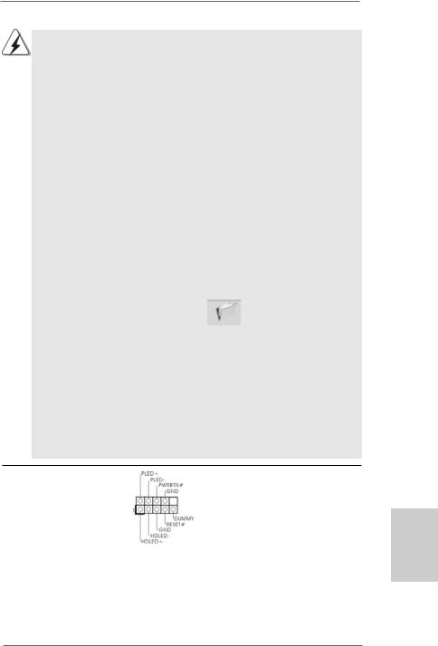
System Panel Header |
This header accommodates |
(9-pin PANEL1) |
several system front panel |
(see p.2 No. 24) |
functions. |
English
1 7
ASRock 770 Extreme3 Motherboard
English
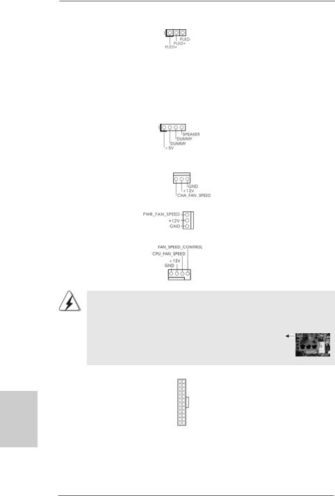
Power LED Header |
|
|
Please connect the chassis |
(3-pin PLED1) |
|
|
power LED to this header to |
(see p.2 No. 19) |
|
|
indicate system power status. |
|
|
|
The LED is on when the system |
|
|
|
is operating. The LED keeps |
|
|
|
blinking in S1 state. The LED is |
|
|
|
off in S3/S4 state or S5 state |
|
|
|
(power off). |
|
|
|
|
Chassis Speaker Header |
|
|
Please connect the chassis |
(4-pin SPEAKER 1) |
|
|
speaker to this header. |
(see p.2 No. 17) |
|
|
|
|
|
|
|
Chassis and Power Fan Connectors |
|
Please connect the fan cables |
|
(3-pin CHA_FAN1) |
|
|
to the fan connectors and |
(see p.2 No. 20) |
|
|
match the black wire to the |
|
|
|
ground pin. |
(3-pin PWR_FAN1) |
|
|
|
(see p.2 No. 37) |
|
|
|
|
|
|
|
CPU Fan Connector |
|
|
Please connect the CPU fan |
(4-pin CPU_FAN1) |
|
|
cable to this connector and |
(see p.2 No. 2) |
|
|
match the black wire to the |
|
|
|
ground pin. |
1 |
2 |
3 |
4 |
Though this motherboard provides 4-Pin CPU fan (Quiet Fan) support, the 3-Pin CPU fan still can work successfully even without the fan speed control function. If you plan to connect the 3-Pin CPU fan to the CPU fan connector on this motherboard, please connect it to Pin 1-3.
|
|
|
Pin 1-3 Connected |
|
|
|
3-Pin Fan Installation |
|
|
|
|
ATX Power Connector |
12 |
24 |
Please connect an ATX power |
(24-pin ATXPWR1) |
|
|
supply to this connector. |
(see p.2 No. 8) |
|
|
|
|
1 |
13 |
|
1 8
ASRock 770 Extreme3 Motherboard
|
Though this motherboard provides 24-pin ATX power connector, |
12 |
24 |
|
it can still work if you adopt a traditional 20-pin ATX power supply. |
||
|
|
|
|
|
To use the 20-pin ATX power supply, please plug your power |
|
|
|
supply along with Pin 1 and Pin 13. |
|
|
|
20-PinATX Power Supply Installation |
1 |
13 |
|
|
||
|
|
|
|
|
|
|
|
ATX 12V Power Connector |
4 |
8 |
|
(8-pin ATX12V1) |
1 |
6 |
|
(see p.2 No. 3) |
|||
|
|
Please connect an ATX 12V power supply to this connector.
|
Though this motherboard provides 8-pin ATX 12V power connector, |
|
|
|
it can still work if you adopt a traditional 4-pin ATX 12V power |
4 |
8 |
|
supply. To use the 4-pin ATX power supply, please plug your |
|
|
|
power supply along with Pin 1 and Pin 5. |
|
|
|
4-PinATX 12V Power Supply Installation |
1 |
6 |
|
|
||
|
|
|
|
|
|
|
|
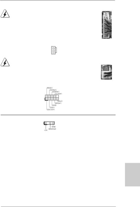
Serial port Header |
This COM1 header supports a |
(9-pin COM1) |
serial port module. |
(see p.2 No.28) |
|
HDMI_SPDIFHeader |
HDMI_SPDIF header, providing |
(3-pin HDMI_SPDIF1) |
SPDIF audio output to HDMI VGA |
(see p.2 No. 31) |
card, allows the system to |
|
con nect HDMI Digital TV/ |
|
projector/LCD devices. Please |
|
connect the HDMI_SPDIF |
on |
connector of HDMI VGA card to |
|
this header. |
English
1 9
ASRock 770 Extreme3 Motherboard
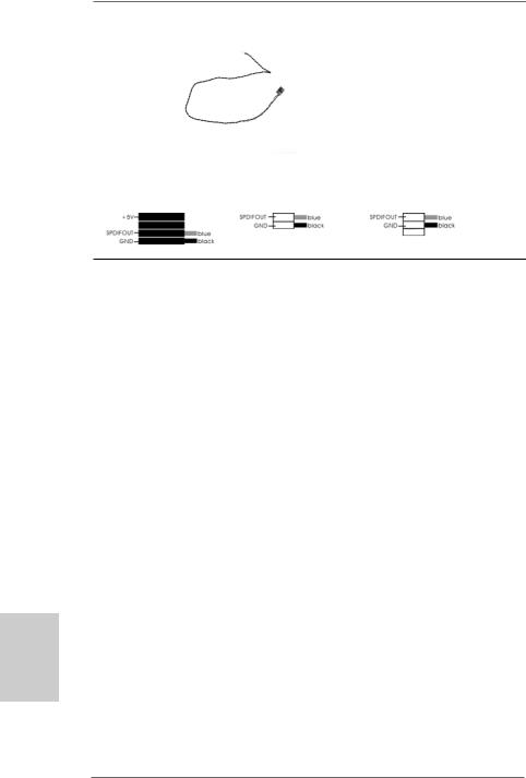
HDMI_SPDIFCable
(Optional) C
B
A
Please connect the black end (A) of HDMI_SPDIF cable to the HDMI_SPDIF header on the motherboard. Then connect the white end (B or C) of HDMI_SPDIF cable to the HDMI_SPDIF connector of HDMI VGA card.
A. black end |
B. white end (2-pin) |
C. white end (3-pin) |
English
2.7Driver Installation Guide
To install the drivers to your system, please insert the support CD to your optical drive first. Then, the drivers compatible to your system can be auto-detected and listed on the support CD driver page. Please follow the order from up to bottom side to install those required drivers. Therefore, the drivers you install can work properly.
2.8Installing Windows® 7 / 7 64-bit / VistaTM /
VistaTM 64-bit / XP / XP 64-bit With RAID Functions
If you want to install Windows® 7 / 7 64-bit / VistaTM / VistaTM 64-bit / XP / XP 64-bit on your SATA / SATAII HDDs with RAID functions, please refer to the document at the following path in the Support CD for detailed procedures:
..\ RAID Installation Guide
2.9Installing Windows® 7 / 7 64-bit / VistaTM /
VistaTM 64-bit / XP / XP 64-bit Without RAID Functions
If you want to install Windows® 7 / 7 64-bit / VistaTM / VistaTM 64-bit / XP / XP 64-bit OS on your SATA / SATAII HDDs without RAID functions, please follow below procedures according to the OS you install.
2.9.1 Installing Windows® XP / XP 64-bit Without RAID Functions
If you want to install Windows® XP / XP 64-bit on your SATA / SATAII HDDs without RAID functions, please follow below steps.
2 0
ASRock 770 Extreme3 Motherboard
Using SATA / SATAII HDDs without NCQ and Hot Plug functions STEP 1: Set up BIOS.
A. |
Enter BIOS SETUP UTILITY |
|
Advanced screen |
|
Storage |
|
|
Configuration.
B.Set the “SATA Operation Mode” option to [IDE].
STEP 2: Install Windows® XP / XP 64-bit OS on your system.
2.9.2 Installing Windows® 7 / 7 64-bit / VistaTM / VistaTM 64-bit Without RAID Functions
If you want to install Windows® 7 / 7 64-bit / VistaTM / VistaTM 64-bit on your SATA /
SATAII HDDs without RAID functions, please follow below steps.
Using SATA / SATAII HDDs without NCQ and Hot Plug functions STEP 1: Set up BIOS.
A. |
Enter BIOS SETUP UTILITY |
|
Advanced screen |
|
Storage |
|
|
Configuration.
B.Set the “SATA Operation Mode” option to [IDE].
STEP 2: Install Windows® 7 / 7 64-bit / VistaTM / VistaTM 64-bit OS on your system.
Using SATA / SATAII HDDs with NCQ and Hot Plug functions
STEP 1: Set Up BIOS.
A. |
Enter BIOS SETUP UTILITY |
|
Advanced screen |
|
Storage |
|
|
Configuration.
B.Set the “SATA Operation Mode” option to [AHCI].
STEP 2: Install Windows® 7 / 7 64-bit / VistaTM / VistaTM 64-bit OS on your system.
2.10 Untied Overclocking Technology
This motherboard supports Untied Overclocking Technology, which means during overclocking, FSB enjoys better margin due to fixed PCI / PCIE buses. Before you enable Untied Overclocking function, please enter “Overclock Mode” option of BIOS setup to set the selection from [Auto] to [CPU, PCIE, Async.]. Therefore, CPU FSB is untied during overclocking, but PCI / PCIE buses are in the fixed mode so that FSB can operate under a more stable overclocking environment.
Please refer to the warning on page 7 for the possible overclocking risk before you apply Untied Overclocking Technology.
2 1
English
ASRock 770 Extreme3 Motherboard

3. BIOS Information
The Flash Memory on the motherboard stores BIOS Setup Utility. When you start up the computer, please press <F2> during the Power-On-Self-Test (POST) to enter BIOS Setup utility; otherwise, POST continues with its test routines. If you wish to enter BIOS Setup after POST, please restart the system by pressing <Ctl> + <Alt> + <Delete>, or pressing the reset button on the system chassis. The BIOS Setup program is designed to be user-friendly. It is a menu-driven program, which allows you to scroll through its various sub-menus and to select among the predetermined choices. For the detailed information about BIOS Setup, please refer to the User Manual (PDF file) contained in the Support CD.
4. Software Support CD information
This motherboard supports various Microsoft® Windows® operating systems: 7 /
7 64-bit / VistaTM / VistaTM 64-bit / XP / XP Media Center / XP 64-bit. The Support CD that came with the motherboard contains necessary drivers and useful utilities that will enhance motherboard features. To begin using the Support CD, insert the CD into your CD-ROM drive. It will display the Main Menu automatically if “AUTORUN” is enabled in your computer. If the Main Menu does not appear automatically, locate and double-click on the file “ASSETUP.EXE” from the “BIN” folder in the Support CD to display the menus.
English
2 2
ASRock 770 Extreme3 Motherboard

1. Einführung
Wir danken Ihnen für den Kauf des ASRock 770 Extreme3 Motherboard, ein zuverlässiges Produkt, welches unter den ständigen, strengen Qualitätskontrollen von ASRock gefertigt wurde. Es bietet Ihnen exzellente Leistung und robustes Design, gemäß der Verpflichtung von ASRock zu Qualität und Halbarkeit.
Diese Schnellinstallationsanleitung führt in das Motherboard und die schrittweise Installation ein. Details über das Motherboard finden Sie in der Bedienungsanleitung auf der Support-CD.
Da sich Motherboard-Spezifikationen und BIOS-Software verändern können, kann der Inhalt dieses Handbuches ebenfalls jederzeit geändert werden. Für den Fall, dass sich Änderungen an diesem Handbuch ergeben, wird eine neue Version auf der ASRock-Website, ohne weitere Ankündigung, verfügbar sein. Die neuesten Grafikkarten und unterstützten CPUs sind auch auf der ASRock-Website aufgelistet.
ASRock-Website: http://www.asrock.com
Wenn Sie technische Unterstützung zu Ihrem Motherboard oder spezifische Informationen zu Ihrem Modell benötigen, besuchen Sie bitte unsere Webseite:
www.asrock.com/support/index.asp
1.1 Kartoninhalt
ASRock 770 Extreme3 Motherboard
(ATX-Formfaktor: 30.5 cm x 20.8 cm; 12.0 Zoll x 8.2 Zoll)
ASRock 770 Extreme3 Schnellinstallationsanleitung
ASRock 770 Extreme3 Support-CD
Ein 80-adriges Ultra-ATA 66/100/133 IDE-Flachbandkabel
Zwei Seriell-ATA- (SATA) Datenkabel (Option)
Ein Serial ATA (SATA) -Festplattenstromkabel (optional)
Ein I/O Shield
Deutsch
2 3
ASRock 770 Extreme3 Motherboard

1.2Spezifikationen
Deutsch
2 4
|
Plattform |
- ATX-Formfaktor: 30.5 cm x 20.8 cm; 12.0 Zoll x 8.2 Zoll |
|
|
- Alle Feste Kondensatordesign (100% in Japan gefertigte, |
|
|
erstklassige leitfähige Polymer-Kondensatoren) |
|
|
|
|
CPU |
- Unterstützung von Socket AM3-Prozessoren: AMD PhenomTM |
|
|
II X4 / X3 / X2 (außer 920 / 940) / Athlon X4 / X3 / X2 / |
|
|
Sempron-Prozessor |
|
|
- Unterstützt CPU bis 140W |
|
|
- Unterstützt AMD OverDriveTM mit ACC-Funktion (Advanced |
|
|
Clock Calibration, Erweiterte Taktkalibrierung) |
|
|
- AMD LIVE!TM-bereit |
|
|
- Unterstützt Cool ‘n’ QuietTM-Technologie von AMD |
|
|
- FSB 2600 MHz (5.2 GT/s) |
|
|
- Unterstützt Untied-Übertaktungstechnologie |
|
|
(siehe VORSICHT 1) |
|
|
- Unterstützt Hyper-Transport- 3.0 Technologie (HT 3.0) |
|
Chipsatz |
- Northbridge: AMD 770 |
|
|
- Southbridge: AMD 710 |
|
|
|
|
Speicher |
- Unterstützung von Dual-Kanal-Speichertechnologie |
|
|
(siehe VORSICHT 2) |
|
|
- 4 x Steckplätze für DDR3 |
|
|
- Unterstützt DDR3 1600/1333/1066/800 non-ECC, |
|
|
ungepufferter Speicher (siehe VORSICHT 3) |
|
|
- Max. Kapazität des Systemspeichers: 16GB |
|
|
(siehe VORSICHT 4) |
|
Erweiterungs- |
- 1 x PCI Express 2.0 x16-Steckplatz (blau für x16-Modus) |
|
steckplätze |
- 2 x PCI Express 2.0 x1-Steckplatz |
|
|
- 3 x PCI -Steckplätze |
|
|
|
|
Audio |
- 7.1 CH HD Audio mit dem Inhalt Schutz |
|
|
(Realtek ALC892 Audio Codec) |
|
|
- Premium Blu-ray-Audio-Unterstützung |
|
LAN |
- PCIE x1 Gigabit LAN 10/100/1000 Mb/s |
|
|
- Realtek RTL8111DL |
|
|
- Unterstützt Wake-On-LAN |
|
E/A-Anschlüsse |
I/O Panel |
|
an der |
- 1 x PS/2-Mausanschluss |
|
Rückseite |
- 1 x PS/2-Tastaturanschluss |
|
|
- 1 x Koaxial-SPDIF-Ausgang |
|
|
- 1 x optischer SPDIF-Ausgang |
|
|
- 5 x Standard-USB 2.0-Anschlüsse |
|
|
|
|
|
|
ASRock 770 Extreme3 Motherboard

|
- 1 x eSATAII-Anschluss |
|
- 1 x Standard-USB 3.0-Anschlüsse |
|
- 1 x RJ-45 LAN Port mit LED (ACT/LINK LED und SPEED LED) |
|
- HD Audiobuchse: Lautsprecher seitlich / Lautsprecher hinten |
|
/ Mitte/Bass / Audioeingang/ Lautsprecher vorne / Mikrofon |
|
(siehe VORSICHT 5) |
SATA3 |
- 2 x SATA 3-Anschlüsse (6,0 Gb/s) durch Marvell SE9123/ |
|
9120; unterstützt NCQ-, AHCIund „Hot Plug“ (Hot-Plugging)- |
|
Funktionen |
|
|
USB 3.0 |
- 1 x USB 3.0-Ports durch Fresco FL1000G; unterstützt |
|
USB 3.0 mit bis zu 5 Gb/s |
Anschlüsse |
- 4 x Serial ATAII 3,0 GB/s-Anschlüsse, unterstützen RAID- |
|
(RAID 0, RAID 1, RAID 10 und JBOD), NCQ, AHCI und “Hot |
|
Plug” Funktionen |
|
- 2 x SATA3 6,0 GB/s-Anschlüsse |
|
- 1 x ATA133 IDE-Anschlüsse (Unterstützt bis 2 IDE-Geräte) |
|
- 1 x FDD-Anschlüsse |
|
- 1 x Infrarot-Modul-Header |
|
- 1 x COM-Anschluss-Header |
|
- 1 x HDMI_SPDIF-Anschluss |
|
- 1 x Betriebs-LED-Header |
|
- CPU/Gehäuse/Stromlüfter-Anschluss |
|
- 24-pin ATX-Netz-Header |
|
- 8-pin anschluss für 12V-ATX-Netzteil |
|
- Interne Audio-Anschlüsse |
|
- Anschluss für Audio auf der Gehäusevorderseite |
|
- 3 x USB 2.0-Anschlüsse (Unterstützung 6 zusätzlicher |
|
USB 2.0-Anschlüsse) (siehe VORSICHT 6) |
BIOS |
- 8Mb AMI BIOS |
|
- AMI legal BIOS mit Unterstützung für “Plug and Play” |
|
- ACPI 1.1-Weckfunktionen |
|
- JumperFree-Modus |
|
- SMBIOS 2.3.1 |
|
- CPU VID Stromspannung Multianpassung |
Support-CD |
- Treiber, Dienstprogramme, Antivirussoftware |
|
(Probeversion), AMD OverDriveTM-Dienstprogramm, |
|
ASRock-Software-Suite (CyberLink DVD Suite und Creative |
|
Sound Blaster X-Fi MB) (OEMund Testversion) |
Einzigartige |
- ASRock OC Tuner (siehe VORSICHT 7) |
Eigenschaft |
- Intelligent Energy Saver (Intelligente Energiesparfunktion) |
|
(siehe VORSICHT 8) |
|
- Sofortstart |
|
|
|
|
Deutsch
2 5
ASRock 770 Extreme3 Motherboard

Deutsch
-ASRock Instant Flash (siehe VORSICHT 9)
-ASRock OC DNA (siehe VORSICHT 10)
-Hybrid Booster:
-Schrittloser CPU-Frequenz-Kontrolle (siehe VORSICHT 11)
-ASRock U-COP (siehe VORSICHT 12)
-Boot Failure Guard (B.F.G. – Systemstartfehlerschutz)
Hardware Monitor - CPU-Temperatursensor
|
- Motherboardtemperaturerkennung |
|
- Drehzahlmessung für CPU/Gehäuse/Stromlüfter |
|
- CPU-Lüftergeräuschdämpfung |
|
- Spannungsüberwachung: +12V, +5V, +3.3V, Vcore |
Betriebssysteme |
- Unterstützt Microsoft® Windows® 7 / 7 64-Bit / VistaTM / |
|
VistaTM 64-Bit / XP / XP Media Center / XP 64-Bit |
Zertifizierungen |
- FCC, CE, WHQL |
-Gemäß Ökodesign-Richtlinie (ErP/EuP) (Stromversorgung gemäß Ökodesign-Richtlinie (ErP/EuP) erforderlich) (siehe VORSICHT 13)
*Für die ausführliche Produktinformation, besuchen Sie bitte unsere Website: http://www.asrock.com
WARNUNG
Beachten Sie bitte, dass Overclocking, einschließlich der Einstellung im BIOS, Anwenden der Untied Overclocking-Technologie oder Verwenden von Overclocking-Werkzeugen von Dritten, mit einem gewissen Risiko behaftet ist. Overclocking kann sich nachteilig auf die Stabilität Ihres Systems auswirken oder sogar Komponenten und Geräte Ihres Systems beschädigen. Es geschieht dann auf eigene Gefahr und auf Ihre Kosten. Wir übernehmen keine Verantwortung für mögliche Schäden, die aufgrund von Overclocking verursacht wurden.
VORSICHT!
1.Dieses Motherboard unterstützt die Untied-Übertaktungstechnologie. Unter “Entkoppelte Übertaktungstechnologie” auf Seite 21 finden Sie detaillierte Informationen.
2.Dieses Motherboard unterstützt Dual-Kanal-Speichertechnologie. Vor Implementierung der Dual-Kanal-Speichertechnologie müssen Sie die Installationsanleitung für die Speichermodule auf Seite 31 zwecks richtiger Installation gelesen haben.
3.Ob die Speichergeschwindigkeit 1600 MHz unterstützt wird, hängt von der von Ihnen eingesetzten AM3-CPU ab. Schauen Sie bitte auf unseren Internetseiten in der Liste mit unterstützten Speichermodulen nach, wenn Sie DDR3 1600-Speichermodule einsetzen möchten.
ASRock-Internetseite: http://www.asrock.com
2 6
ASRock 770 Extreme3 Motherboard

4.Durch Betriebssystem-Einschränkungen kann die tatsächliche Speichergröße weniger als 4 GB betragen, da unter Windows® 7 / Vista™ / XP etwas Speicher zur Nutzung durch das System reserviert wird. Unter Windows® OS mit 64-Bit-CPU besteht diese Einschränkung nicht.
5.Der Mikrofoneingang dieses Motherboards unterstützt Stereound MonoModi. Der Audioausgang dieses Motherboards unterstützt 2-Kanal-, 4- Kanal-, 6-Kanal- und 8-Kanal-Modi. Stellen Sie die richtige Verbindung anhand der Tabelle auf Seite 3 her.
6.Das Power Management für USB 2.0 arbeitet unter Microsoft® Windows® 7 64-Bit / 7 / VistaTM 64-Bit / VistaTM / XP 64-Bit / XP SP1 oder SP2 einwandfrei.
7.Es ist ein benutzerfreundlicher ASRock Übertaktenswerkzeug, das erlaubt, dass Sie Ihr System durch den Hardware-Monitor Funktion zu überblicken und Ihre Hardware-Geräte übertakten, um die beste Systemleistung unter der Windows® Umgebung zu erreichen. Besuchen Sie bitte unsere Website für die Operationsverfahren von ASRock OC Tuner. ASRock-Website: http://www.asrock.com
8.Mit einer eigenen, modernen Hardware und speziellem Softwaredesign, bietet der Intelligent Energy Saver eine revolutionäre Technologie zur bisher unerreichten Energieeinsparung. Ein Spannungsregler kann die Anzahl von Ausgangsphasen zur Effektivitätsverbessserung reduzieren, wenn sich die CPU im Leerlauf befindet. Mit anderen Worten: Sie genießen außergewöhnliche Energieeinsparung und verbesserten Wirkungsgrad ohne Leistungseinschränkungen. Wenn Sie die Intelligent Energy Saver-Funktion nutzen möchten, aktivieren Sie zuvor die „Cool ‘n’ Quiet“-Option im BIOS. Weitere Bedienungshinweise zum Intelligent Energy Saver finden Sie auf unseren Internetseiten. ASRock-Internetseite: http://www.asrock.com
9.ASRock Instant Flash ist ein im Flash-ROM eingebettetes BIOS-Flash- Programm. Mithilfe dieses praktischen BIOS-Aktualisierungswerkzeugs können Sie das System-BIOS aktualisieren, ohne dafür zuerst Betriebssysteme wie MS-DOS oder Windows® aufrufen zu müssen. Mit diesem Programm bekommen Sie durch Drücken der <F6>-Taste während des POST-Vorgangs oder durch Drücken der <F2>-Taste im BIOS-Setup-Menü Zugang zu ASRock Instant Flash. Sie brauchen dieses Werkzeug einfach nur zu starten und die neue BIOS-Datei auf Ihrem USB-Flash-Laufwerk, Diskettenlaufwerk oder der Festplatte zu speichern, und schon können Sie Ihr BIOS mit nur wenigen Klickvorgängen ohne Bereitstellung einer zusätzlichen Diskette oder eines anderen komplizierten Flash-Programms aktualisieren. Achten Sie darauf, dass das USB-Flash-Laufwerk oder die Festplatte das Dateisystem FAT32/16/12 benutzen muss.
Deutsch
2 7
ASRock 770 Extreme3 Motherboard

10.Allein der Name – OC DNA* – beschreibt es wörtlich, was die Software zu leisten vermag. OC DNA ist ein von ASRock exklusiv entwickeltes Dienstprogramm, das Nutzern eine bequeme Möglichkeit bietet, Übertaktungseinstellungen aufzuzeichnen und sie Anderen mitzuteilen. Es hilft Ihnen, Ihre Übertaktungsaufzeichnung im Betriebssystem zu speichern und vereinfacht den komplizierten Aufzeichnungsvorgang von Übertaktungseinstellungen. Mit OC DNA können Sie Ihre Übertaktungseinstellungen als Profil abspeichern und Ihren Freunden zugänglich machen! Ihre Freunde können dann das Übertaktungsprofil auf ihren eigenen Systemen laden, um dieselben Übertaktungseinstellungen wie Sie zu erhalten! Beachten Sie bitte, dass das Übertaktungsprofil nur bei einem identischen Motherboard gemeinsam genutzt und funktionsfähig gemacht werden kann.
11.Obwohl dieses Motherboard stufenlose Steuerung bietet, wird Overclocking nicht empfohlen. Frequenzen, die von den empfohlenen CPU-Busfrequenzen abweichen, können Instabilität des Systems verursachen oder die CPU beschädigen.
12.Wird eine Überhitzung der CPU registriert, führt das System einen automatischen Shutdown durch. Bevor Sie das System neu starten, prüfen Sie bitte, ob der CPU-Lüfter am Motherboard richtig funktioniert, und stecken Sie bitte den Stromkabelstecker aus und dann wieder ein. Um die Wärmeableitung zu verbessern, bitte nicht vergessen, etwas Wärmeleitpaste zwischen CPU und Kühlkörper zu sprühen.
13.EuP steht für Energy Using Product und kennzeichnet die ÖkodesignRichtlinie, die von der Europäischen Gemeinschaft zur Festlegung des Energieverbrauchs von vollständigen Systemen in Kraft gesetzt wurde. Gemäß dieser Ökodesign-Richtlinie (EuP) muss der gesamte Netzstromverbrauch von vollständigen Systemen unter 1,00 Watt liegen, wenn sie ausgeschaltet sind. Um dem EuP-Standard zu entsprechen, sind ein EuP-fähiges Motherboard und eine EuP-fähige Stromversorgung erforderlich. Gemäß einer Empfehlung von Intel muss eine EuP-fähige Stromversorgung dem Standard entsprechen, was bedeutet, dass bei einem Stromverbrauch von 100 mA die 5-Volt-Standby-Energieeffizienz höher als 50% sein sollte. Für die Wahl einer EuP-fähigen Stromversorgung empfehlen wir Ihnen, weitere Details beim Hersteller der Stromversorgung abzufragen.
Deutsch
2 8
ASRock 770 Extreme3 Motherboard
2. Installation
Dies ist ein Motherboard mit einem ATX-Formfaktor (12,0 Zoll x 8,2 Zoll, 30,5 cm x 20,8 cm). Vor Installation des Motherboards müssen Sie die Konfiguration Ihres Gehäuses dahingehend überprüfen, ob das Motherboard dort hineinpasst.
Sicherheitshinweise vor der Montage
Bitte nehmen Sie die folgende Sicherheitshinweise zur Kenntnis, bevor Sie das Motherboard einbauen oder Veränderungen an den Einstellungen vornehmen.
Vor dem Einoder Ausbauen einer Komponent müssen Sie sicherstellen, dass der Netzschalter ausgeschaltet oder die Netzleitung von der Steckdose abgezogen ist. Andernfalls könnten das Motherboard, Peripheriegeräte und/ oder Komponenten schwer beschädigt werden.
1.Trennen Sie das System vom Stromnetz, bevor Sie eine Systemkomponente berühren, da es sonst zu schweren Schäden am Motherboard oder den sonstigen internen, bzw. externen Komponenten kommen kann.
2.Um Schäden aufgrund von statischer Elektrizität zu vermeiden, das Motherboard NIEMALS auf einen Teppich o.ä.legen. Denken Sie außerem daran, immer ein geerdetes Armband zu tragen oder ein geerdetes Objekt aus Metall zu berühren, bevor Sie mit Systemkomponenten hantieren.
3.Halten Sie Komponenten immer an den Rändern und vermeiden Sie Berührungen mit den ICs.
4.Wenn Sie Komponenten ausbauen, legen Sie sie immer auf eine antistatische Unterlage, oder zurück in die Tüte, mit der die Komponente geliefert wurde.
5.Wenn Sie das Motherboard mit den Schrauben an dem Computergehäuse befestigen, überziehen Sie bitte die Schrauben nicht! Das Motherboard kann sonst beschädigt werden.
Deutsch
2 9
ASRock 770 Extreme3 Motherboard
2.1 CPU Installation
Schritt 1: Öffnen Sie den CPU-Sockel, indem sie den Hebel leicht zur Seite und dann nach oben ziehen, auf einen Winkel von 90°.
Schritt 2: Positionieren Sie die CPU genau so über dem Sockel, dass sich die Ecke der CPU mit dem goldenen Dreieck exakt über der Ecke des Sockels befindet, die mit einem kleinen Dreieck gekennzeichnet ist.
Schritt 3: Drücken Sie die CPU vorsichtig in den Sockel.
Die CPU sollte problemlos in den Sockel passen. Drücken Sie die CPU nicht mit Gewalt in den Sockel, damit sich die Pins nicht verbiegen. Überprüfen Sie die Ausrichtung und suchen nach verbogenen Pins, sollte die CPU nicht in den Sockel passen.
Schritt 4: Wenn die CPU korrekt im Sockel sitzt, leicht mit dem Finger draufdrücken und gleichzeitig den Hebel nach unten drücken, bis er hörbar einrastet.
Deutsch
Goldenes Dreieck der
CPU
|
Kleines Dreieck der Sockelecke |
|
SCHRITT 1: |
SCHRITT 2 / SCHRITT 3: |
SCHRITT 4: |
Ziehen Sie den |
Richten Sie das goldene |
Drücken Sie den Sockelhebel |
Sockelhebel hoch |
Dreieck der CPU mit dem |
nach unten und rasten Sie |
|
kleinen Dreieck der |
ihn ein |
|
Sockeleckeaus |
|
2.2Installation des CPU-Lüfters und des Kühlkörpers
Nachdem Sie die CPU auf diesem Motherboard installiert haben, müssen Sie einen größeren Kühlkörper und Lüfter installieren, um Wärme abzuleiten. Zwischen CPU und Kühlkörper müssen Sie auch Wärmeleitpaste auftragen, um die Wärmeableitung zu verbessern. Vergewissern Sie sich, dass die CPU und der Kühlkörper gut befestigt sind und einen guten Kontakt zueinander haben. Verbinden Sie dann den CPULüfter mit dem CPU-LÜFTER-Anschluss (CPU_FAN1, siehe Seite 2, Nr. 2). Beziehen Sie sich für eine richtige Installation auf die Handbücher des CPULüfters und des Kühlkörpers.
3 0
ASRock 770 Extreme3 Motherboard
 Loading...