


Ariens 924329, 924115, 924501, 924110, 924328 User Manual
...924 Sno-Thro
Service Manual
Models 924108 - 924113, 924115, 924327 - 924330, 924500, 924501
00040700 02/00
Printed in USA

TABLE OF CONTENTS
Section 1 - Introduction . . . . . . . . . . . . . . . . . 1.3
1.1 The Manual . . . . . . . . . . . . . . . . . . . . . . . 1.3
1.2 Service and Replacement Parts . . . . . . . 1.3
1.3 Product Registration . . . . . . . . . . . . . . . . 1.3
1.4 Unauthorized Replacement Parts . . . . . . 1.3
1.5 Disclaimer . . . . . . . . . . . . . . . . . . . . . . . . 1.3
1.6 Technical Service Communications . . . . . 1.3
Section 2 - Safety . . . . . . . . . . . . . . . . . . . . . . 2.4
2.1 Safety Alerts . . . . . . . . . . . . . . . . . . . . . . 2.4
2.2 Signal Words . . . . . . . . . . . . . . . . . . . . . . 2.4
2.3 Notations . . . . . . . . . . . . . . . . . . . . . . . . . 2.4
2.4 Practices and Laws . . . . . . . . . . . . . . . . . 2.4
2.5 Required Operator Training . . . . . . . . . . . 2.4
2.6 Preparation . . . . . . . . . . . . . . . . . . . . . . . 2.4
2.7 Service Position . . . . . . . . . . . . . . . . . . . . 2.4
2.8 Cleaning and Storage . . . . . . . . . . . . . . . 2.4
2.9 Safety Rules. . . . . . . . . . . . . . . . . . . . . . . 2.5
Section 3 - Specifications . . . . . . . . . . . . . . . 3.7
Section 4 - General Maintenance &
Adjustments. . . . . . . . . . . . . . . . . . . . . . . .4.10
4.1 Controls and Features . . . . . . . . . . . . . . .4.10
4.2 Service Positions . . . . . . . . . . . . . . . . . . .4.11
4.3 Filling The Fuel Tank . . . . . . . . . . . . . . . .4.11
4.4 Fuel Shut-Off Valve . . . . . . . . . . . . . . . . .4.12
4.5 General Lubrication . . . . . . . . . . . . . . . . .4.12
4.6 Auger Gearcase. . . . . . . . . . . . . . . . . . . .4.13
4.7 Engine . . . . . . . . . . . . . . . . . . . . . . . . . . .4.13
4.8 Traction Drive Belt . . . . . . . . . . . . . . . . . .4.13
4.9 Attachment Drive Belt . . . . . . . . . . . . . . .4.14
4.10 Shear Bolts . . . . . . . . . . . . . . . . . . . . . .4.14
4.11 Tire Pressure . . . . . . . . . . . . . . . . . . . . .4.15
4.12 Adjustments . . . . . . . . . . . . . . . . . . . . . .4.15
Section 5 - HandleBars & Controls . . . . . . . . 5.18
5.1 Lower Handlebar . . . . . . . . . . . . . . . . . . . 5.18
5.2 Attachment Clutch Handle . . . . . . . . . . . .5.18
5.3 Wheel Drive Clutch Lever & Traction Cable5.18
5.4 Clutch Yoke and Fork . . . . . . . . . . . . . . . .5.19
Section 6 - Engine . . . . . . . . . . . . . . . . . . . . . .6.20
6.1 Engine Troubleshooting . . . . . . . . . . . . . .6.20
6.2 Removing the Engine. . . . . . . . . . . . . . . .6.21
6.3 Installing The Engine . . . . . . . . . . . . . . . .6.21
Section 7 - Reduction Drive . . . . . . . . . . . . . .7.22
7.1 Differential, Lockout, And Axle . . . . . . . . .7.22
7.2 Spur Gear and Axle . . . . . . . . . . . . . . . . .7.22
7.3 Axle Bearings. . . . . . . . . . . . . . . . . . . . . .7.22
7.4 Drive Chain . . . . . . . . . . . . . . . . . . . . . . .7.23
7.5 Drive Chain Adjustment . . . . . . . . . . . . . .7.23
Section 8 - Friction Wheel Drive . . . . . . . . . .8.24
8.1 Friction Wheel . . . . . . . . . . . . . . . . . . . . .8.24
8.2 Friction Wheel Carrier . . . . . . . . . . . . . . .8.24
8.3 Drive Plate Spindle . . . . . . . . . . . . . . . . .8.24
Section 9 - Auger/Impeller . . . . . . . . . . . . . . .9.26
9.1 Auger/Impeller Removal. . . . . . . . . . . . . .9.26
9.2 Scraper Blade . . . . . . . . . . . . . . . . . . . . .9.26
9.3 Shear Bolts . . . . . . . . . . . . . . . . . . . . . . .9.26
9.4 Discharge Chute . . . . . . . . . . . . . . . . . . .9.27
9.5 Deflector. . . . . . . . . . . . . . . . . . . . . . . . . .9.28
9.6 Runners . . . . . . . . . . . . . . . . . . . . . . . . . .9.28
Section 10 - Gear Case . . . . . . . . . . . . . . . . . 10.29
10.1 Cast Iron Gear Case (Worm Gear) . . . 10.29
10.2 Aluminum Gear Case. . . . . . . . . . . . . . 10.29
Section 11 - Electrical . . . . . . . . . . . . . . . . . . 11.32
11.1 Continuity Diagram. . . . . . . . . . . . . . . . 11.32
11.2 Wiring Diagram . . . . . . . . . . . . . . . . . . 11.33
2
SECTION 1 - INTRODUCTION
1.1 THE MANUAL
It is the purpose of this manual to provide complete instructions for service, maintenance, disassembly, repair, and installation of the mechanical components for the 924 Snow-Thro.
Dealer trained service personnel should use this manual as a supplement to and reminder of the training sessions conducted by the company.
Read all information for servicing a part of system before repair work is started to avoid needless disassembly.
Operation
Before operation of the unit, carefully and completely read manuals supplied with the unit. The contents will provide you with an understanding of safety instructions and controls during normal operation and maintenance.
Safety Messages
For your safety and the safety of others always read, understand, and follow all DANGER, WARNING, and CAUTION messages found in manuals and on safety decals.
Directional Reference
All reference to left, right, front, or rear are given from the operator in the operator position and facing the direction of forward travel.
1.2 SERVICE AND REPLACEMENT PARTS
When ordering publications, replacement parts, or making service inquiries, know the Model and Serial numbers of your unit and engine.
Numbers are located on the product registration form in the unit literature package. They are printed on a serial number label, located on the frame of your unit.
Figure 1 |
OS0791 |
1.3 PRODUCT REGISTRATION
A warranty registration card must be filled out, signed, and returned at the time of purchase. This card activates the warranty. Claims meeting requirements during limited warranty period will be honored.
1.4 UNAUTHORIZED REPLACEMENT PARTS
Use only Ariens replacement parts. The replacement of any part on this vehicle with anything other than a Ariens authorized replacement part may adversely affect the performance, durability, or safety of this unit and may void the warranty. Ariens disclaims liability for any claims or damages, whether warranty, property damage, personal injury, or death arising out of the use of unauthorized replacement parts.
1.5 DISCLAIMER
Ariens reserves the right to discontinue, make changes to, and add improvements upon its products at any time without public notice or obligation. The descriptions and specifications contained in this manual were in effect at printing. Equipment described within this manual may be optional. Some illustrations may not be applicable to your unit.
1.6 TECHNICAL SERVICE COMMUNICATIONS
Ariens Technical Service communicates information to the field using Service Letters, Service Bulletins, Product Notices, and Campaigns. Each communication signifies a type of information and priority. The dealer is responsible to carry out the directive provided in the communication. The types of communication are:
Service Letter - General technical information for the dealer. Technical information on how to service the product and product improvements.
Service Bulletin - Notification to update products to resolve certain issues or a notification of a policy change.
Product Notices - Notification of limited product located in a certain region. This is a limited distribution to only those who received the product involved.
Campaigns - Notification of a safety related issue. All product must be updated and are tracked by the factory until all units are corrected.
1 - 3

SECTION 2 - SAFETY
2.1 SAFETY ALERTS
Look for these symbols to point out important safety precautions. They mean:
Attention!
Personal Safety Is Involved!
Become Alert!
Obey The Message!
2.2 SIGNAL WORDS
The safety alert symbol is used in decals on the unit and with proper operation procedures in this manual. They alert you to the existence and relative degree of hazards.
Understand the safety message. It contains important information about personal safety on or near the unit.
DANGER: IMMINENTLY HAZARDOUS SITUATION! If not avoided, WILL RESULT in death or serious injury.
WARNING: POTENTIALLY HAZARDOUS SITUATION! If not avoided, COULD RESULT in death or serious injury.
CAUTION: POTENTIALLY HAZARDOUS SITUATION! If not avoided, MAY RESULT in minor or moderate injury. It may also be used to alert against unsafe practices.
2.3 NOTATIONS
NOTE: General reference information for proper operation and maintenance practices.
IMPORTANT: Specific procedures or information required to prevent damage to unit or attachment.
2.4 PRACTICES AND LAWS
Practice usual and customary safe working precautions, for the benefit of yourself and others. Understand and follow all safety messages. Be alert to unsafe conditions and the possibility of minor, moderate, or serious injury or death. Learn applicable rules and laws in your area.
2.5 REQUIRED OPERATOR TRAINING
Original purchaser of this unit was instructed by the seller on safe and proper operation. If unit is to be used by someone other than original purchaser; loaned, rented or sold, ALWAYS provide this manual and any needed safety training before operation.
2.6 PREPARATION
Before starting any removal of parts, proper preparation is very important for efficient work. A clean work area at the start of each job will allow you to perform service repairs easily and quickly.
To reduce the incidence of misplaced tools or parts, place removed components with all attaching hardware in the disassembly order on a clean work surface. Organization is a key part of proper reassembly.
Tools, instruments, and parts needed for the job should be gathered before work is started. Interrupting a job to locate tools or parts is a needless delay. A list of required special tools has been included in this manual.
2.7 SERVICE POSITION
WARNING: ALWAYS block wheels and know that jack stands or blocks used are stable, strong, or secure and will hold the weight of the unit during maintenance.
To ensure the unit is positioned in the proper service position place unit on a flat level surface. ALWAYS stop engine. Assure unit is secure and will not tip over. Strap and clamp onto lift if used.
For additional requirements see section on service position.
2.8 CLEANING AND STORAGE
WARNING: AVOID SHARP EDGES which can cut. Movement of parts can cut off fingers or a hand. Wear gloves, and use extreme caution when servicing.
IMPORTANT: Never spray unit with water or store unit outdoors to help prevent sealed bearing rust or corrosion. Water can seep into sealed bearings and reduce component life. Bearings are sealed against dirt and debris only.
A unit that is excessively dirty should be cleaned before work starts. Cleaning will occasionally uncover trouble sources. Dirt and abrasive dust reduce the efficient work life of parts and can lead to costly replacement.
When taking unit out of extended storage:
1.Check for any damage or loose parts. Repair, replace, or tighten hardware before operation.
2.If a preservative fluid was used in fuel tank, drain and discard. Fill fuel tank with fresh new fuel.
2 - 4
2.9 SAFETY RULES
Walk Around Inspection
Complete a walk around inspection of unit and work area to understand:
•Work area.
•Your unit.
•All safety decals.
Work Area
ALWAYS check overhead and side clearances carefully before operation. ALWAYS be aware of traffic when operating along streets or curbs.
ALWAYS keep hands and feet within the limits of the unit.
Keep children, people, and animals away. Keep children out of work area and under watchful care of a responsible adult.
Keep area of operation clear of all toys, pets, and debris. Stay alert for hidden hazards.
DO NOT run engine in an enclosed area. Always provide good ventilation.
Unit
ALWAYS keep protective structures, guards, and panels in good repair, in place and securely fastened. NEVER modify or remove safety devices.
Operation
Understand:
•How to operate all controls
•The functions of all controls
•How to STOP in an Emergency
•Speed ranges
Before starting engine, disengage auxiliary power.
Always back up slowly. Always look down and behind before and while backing.
Never leave a running unit unattended. ALWAYS shut off auxiliary power, lower throttle setting, and stop engine before leaving unit. ALWAYS remove key to prevent unauthorized use.
ALWAYS operate unit in good visibility and light.
Fuel is highly flammable and its vapors can explode. Use ONLY approved RED fuel containers.
NO Smoking!
NO Sparks!
NO Flames!
Allow engine to cool before servicing.
NEVER fill fuel tank when engine is running, hot, or unit is indoors.
Abnormal Vibrations are a warning of trouble. Striking a foreign object can damage unit. Stop unit and engine. Wait for all moving parts to stop. Remove wire from spark plug. Inspect unit and make any necessary repairs before restart.
Hazardous Slopes
DO NOT operate on steep slopes. Avoid operating on slopes. When you must operate on a slope, travel up and down the slope. Never operate cross a slope.
Never operate on a slope greater than 10 degrees.
Child Safety
NEVER allow children to operate or play on or near unit. Be alert and shut off unit if children enter area.
Personal Safety
Read and obey all warning, caution, and instructions on the unit and in provided manuals.
•Only trained adults may operate unit.
•Training includes actual operation.
•Clearly understand instructions.
•Be alert! Conditions can change.
NEVER operate unit after or during the use of medication, drugs or alcohol. Safe operation requires your complete and unimpaired attention at all times.
NEVER allow anyone to operate the unit when their alertness or coordination is impaired.
DO NOT operate unit without wearing adequate outer garments. Wear adequate safety gear and protective gloves. Wear proper footwear to improve footing on slippery surfaces.
Protect eyes, face, and head from objects that may be thrown from unit. Wear appropriate hearing protection.
Avoid Sharp Edges. Sharp edges can cut. Moving parts can cut or amputate fingers or a hand. Wear gloves to service unit when handling sharp edges.
ALWAYS keep hands away from any pinch points.
ALWAYS keep hands and feet away from all moving parts during operation. Moving parts can cut off body parts.
DO NOT touch unit parts which might be hot from operation. Allow parts to cool before attempting to maintain, adjust, or service.
Controls
Come to a complete stop before reversing.
Never jerk the control levers. Always use a steady even action to achieve smooth control.
Always be aware of obstructions that may cause injury to operator or damage to the unit.
Keep alert with eyes fixed in direction of travel.
Maintenance
ALWAYS maintain unit in safe operating condition. Damaged or worn out muffler can cause fire or explosion.
Check the conditions of the unit at the end of each day and repair any damage or defects.
Keep nuts and bolts tight and keep equipment in safe operating conditions.
2 - 5
Before maintenance, adjustments, or service (except where specifically recommended), shut off engine.
Allow hot parts to cool.
Keep unit free of dirt, stones, and other debris. Clean up oil or fuel spills.
Storage
DO NOT store unit inside a building with fuel in the fuel tank where any ignition sources are present. Allow unit to cool completely.
ALWAYS clean unit before extended storage. See Engine Manual for proper storage.
Battery
Avoid Electric Shock. DO NOT reverse battery connections.
Explosive Gases! Poisonous battery fluid contains sulfuric acid and its contact with skin, eyes, or clothing can cause severe burns.
No flames. No sparks. No smoking near battery.
Always wear safety glasses and protective gear near battery.
DO NOT TIP battery beyond a 45o angle in any direction.
ALWAYS KEEP BATTERIES OUT OF REACH of children.
Transport
Use extra care when loading or unloading unit onto trailer or truck. Secure unit chassis to transport vehicle. NEVER secure from rods or linkages that could be damaged.
2 - 6

SECTION 3 - SPECIFICATIONS
Model Number |
924108 |
924109 |
924110 |
924111 |
924112 |
Model |
ST 824 SLE |
ST 1028 SLE |
ST 824 DLE |
SB 936 LE |
ST 928 LE |
Engine - manufacturer |
Tecumseh |
Tecumseh |
Tecumseh |
Tecumseh |
Tecumseh |
|
HMSK80 |
HMSK100 |
HMSK80 |
OHSK90 |
OHSK90 |
|
|
|
|
|
|
Fuel |
Unleaded |
Unleaded |
Unleaded |
Unleaded |
Unleaded |
|
|
|
|
|
|
Fuel Tank Capacity |
1 gallon |
1 gallon |
1 gallon |
1 gallon |
1 gallon |
|
|
|
|
|
|
Governed RPM |
3600 ± 150 |
3600 ± 150 |
3600 ± 150 |
3600 ± 150 |
3600 ± 150 |
|
|
|
|
|
|
Crank Case Capacity |
21 oz. |
21 oz. |
21 oz. |
21 oz. |
21 oz. |
|
|
|
|
|
|
Engine Oil |
5W30 below 40o |
5W30 below 40o |
5W30 below 40o |
5W30 below 40o |
5W30 below 40o |
|
30W above 40o |
30W above 40o |
30W above 40o |
30W above 40o |
30W above 40o |
Spark Plug Gap/Type |
.030/Champion |
.030/Champion |
.030/Champion |
.030/Champion |
.030/Champion |
|
|
|
|
|
|
Drive/Differential |
Disc-O-Matic/No |
Disc-O-Matic/No |
Disc-O-Matic/Yes |
Disc-O-Matic/Yes |
Disc-O-Matic/Yes |
|
|
|
|
|
|
Speeds-Forward |
6 |
6 |
6 |
6 |
6 |
|
|
|
|
|
|
-Reverse |
2 |
2 |
2 |
2 |
2 |
|
|
|
|
|
|
Tire Size |
16/4.80-8 |
16/6.50-8 |
16/4.80-8 |
16/6.50-8 |
16/6.50-8 |
|
|
|
|
|
|
Tire Pressure |
20 PSI |
20 PSI |
20 PSI |
20 PSI |
20 PSI |
|
|
|
|
|
|
Discharge Distance (ft.) |
5 - 45 |
5 - 45 |
5 - 45 |
N/A |
5 - 50 |
|
|
|
|
|
|
Chute Turning Radius |
220o |
220o |
220o |
N/A |
220o |
Adjustable Skid Shoes |
Yes |
Yes |
Yes |
N/A |
Yes |
|
|
|
|
|
|
Auger Size (in.) dia. |
15 |
15 |
15 |
N/A |
16 |
|
|
|
|
|
|
Auger RPM |
110 |
110 |
110 |
N/A |
110 |
|
|
|
|
|
|
Auger Clutched |
Belt Idler |
Belt Idler |
Belt Idler |
N/A |
Belt Idler |
|
Clutched |
Clutched |
Clutched |
|
Clutched |
|
|
|
|
|
|
Impeller Size (in.) dia. |
12 |
12 |
12 |
N/A |
12 |
|
|
|
|
|
|
Impeller RPM |
1100 |
1100 |
1100 |
N/A |
1100 |
|
|
|
|
|
|
Gear Case Lube |
L - 2 |
L - 2 |
L - 2 |
N/A |
L - 2 |
|
|
|
|
|
|
Blower Housing Height (in.) |
20 |
20 |
20 |
N/A |
23.5 |
|
|
|
|
|
|
Blower Housing Width (in.) |
24 |
28 |
24 |
N/A |
28 |
|
|
|
|
|
|
Blower Housing Weight or |
52407400 |
52407400 |
52407400 |
52407400 |
52407400 |
Snow Brush |
|
|
|
|
|
|
|
|
|
|
|
Slicer Bars |
71099700 |
71099700 |
71099700 |
N/A |
71099700 |
|
|
|
|
|
|
Headlight Kit |
72402500 |
72402500 |
72402500 |
72402500 |
72402500 |
|
|
|
|
|
|
Electric Starter Kit |
N/A |
N/A |
N/A |
N/A |
N/A |
|
|
|
|
|
|
Rotary Broom |
82401300 |
82401300 |
82401300 |
82401300 |
82401300 |
|
|
|
|
|
|
Tiller/Lawn Edger |
N/A |
N/A |
N/A |
N/A |
N/A |
|
|
|
|
|
|
Remote Deflector |
72405300 |
Standard |
72405300 |
N/A |
72405300 |
|
|
|
|
|
|
Service Kit |
72405400 |
72405500 |
7240600 |
|
72406100 |
|
|
|
|
|
|
Front Weight |
52407400 |
52407400 |
52407400 |
52407400 |
52407400 |
|
|
|
|
|
|
3 - 7
Model Number |
924327 |
924328 |
924329 |
924330 |
924500 |
Model |
ST 1028 SLE |
ST 824 DLE |
ST 928 LE |
SB 1132 LE |
ST 1336 LE |
Engine - manufacturer |
Tecumseh |
Tecumseh |
Tecumseh |
Tecumseh |
Tecumseh |
|
HMSK100 |
HMSK80 |
OHSK90 |
OHSK110 |
OHSK130 |
|
|
|
|
|
|
Fuel |
Unleaded |
Unleaded |
Unleaded |
Unleaded |
Unleaded |
|
|
|
|
|
|
Fuel Tank Capacity |
1 gallon |
1 gallon |
1 gallon |
1 gallon |
1 gallon |
|
|
|
|
|
|
Idle RPM |
1800 |
1800 |
1800 |
1800 |
1800 |
|
|
|
|
|
|
Governed RPM |
3600 ± 150 |
3600 ± 150 |
3600 ± 150 |
3600 ± 150 |
3600 ± 150 |
|
|
|
|
|
|
Crank Case Capacity |
21 oz. |
21 oz. |
21 oz. |
21 oz. |
21 oz. |
|
|
|
|
|
|
Engine Oil |
5W30 below 40o |
5W30 below 40o |
5W30 below 40o |
5W30 below 40o |
5W30 below 40o |
|
30W above 40o |
30W above 40o |
30W above 40o |
30W above 40o |
30W above 40o |
Spark Plug Gap/Type |
.030/Champion |
.030/Champion |
.030/Champion |
.030/Champion |
.030/Champion |
|
|
|
|
|
|
Drive/Differential |
Disc-O-Matic/No |
Disc-O-Matic/Yes |
Disc-O-Matic/Yes |
Disc-O-Matic/Yes |
Disc-O-Matic/Yes |
|
|
|
|
|
|
Speeds-Forward |
6 |
6 |
6 |
6 |
6 |
|
|
|
|
|
|
-Reverse |
2 |
2 |
2 |
2 |
2 |
|
|
|
|
|
|
Tire Size |
16/6.50-8 |
16/4.80-8 |
16/6.50-8 |
16/6.50-8 |
16/6.50-8 |
|
|
|
|
|
|
Tire Pressure |
20 PSI |
20 PSI |
20 PSI |
20 PSI |
20 PSI |
|
|
|
|
|
|
Discharge Distance (ft.) |
5 - 45 |
5 - 45 |
5 - 50 |
5 - 50 |
5 - 50 |
|
|
|
|
|
|
Chute Turning Radius |
220o |
220o |
220o |
220o |
220o |
Adjustable Skid Shoes |
Yes |
Yes |
Yes |
Yes |
Yes |
|
|
|
|
|
|
Auger Size (in.) dia. |
15 |
15 |
16 |
16 |
16 |
|
|
|
|
|
|
Auger RPM |
110 |
110 |
110 |
110 |
110 |
|
|
|
|
|
|
Auger Clutched |
Belt Idler |
Belt Idler |
Belt Idler |
Belt Idler |
Belt Idler |
|
Clutched |
Clutched |
Clutched |
Clutched |
Clutched |
|
|
|
|
|
|
Impeller Size (in.) dia. |
12 |
12 |
12 |
12 |
14 |
|
|
|
|
|
|
Impeller RPM |
1100 |
1100 |
1100 |
1100 |
1100 |
|
|
|
|
|
|
Gear Case Lube |
L - 2 |
L - 2 |
L - 2 |
L - 2 |
L - 2 |
|
|
|
|
|
|
Blower Housing Height (in.) |
20 |
20 |
23.5 |
23.5 |
21.5 |
|
|
|
|
|
|
Blower Housing Width (in.) |
28 |
24 |
28 |
32 |
36 |
|
|
|
|
|
|
Blower Housing Weight |
52407400 |
52407400 |
52407400 |
52407400 |
52407400 |
|
|
|
|
|
|
Slicer Bars |
71099700 |
71099700 |
71099700 |
71099700 |
71099700 |
|
|
|
|
|
|
Headlight Kit |
N/A |
72402500 |
72402500 |
72402500 |
72402500 |
|
|
|
|
|
|
Electric Starter Kit |
N/A |
N/A |
N/A |
N/A |
STD |
|
|
|
|
|
|
Rotary Broom |
82401300 |
82401300 |
82401300 |
82401300 |
82401300 |
|
|
|
|
|
|
Tiller/Lawn Edger |
N/A |
N/A |
N/A |
N/A |
N/A |
|
|
|
|
|
|
Remote Deflector |
Standard |
N/A |
72405300 |
Standard |
Standard |
|
|
|
|
|
|
Service Kit |
|
|
|
|
72405600 |
|
|
|
|
|
|
Front Weight |
52407400 |
52407400 |
52407400 |
52407400 |
52407400 |
|
|
|
|
|
|
3 - 8
Model Number |
924113 |
924115 |
924501 |
|
|
Model |
ST 1132 LE |
ST 1028 SLE |
ST 1336 LE |
|
|
Engine - manufacturer |
Tecumseh |
Tecumseh |
Tecumseh |
|
|
|
OHSK110 |
HMSK100 |
OHSK130 |
|
|
|
|
|
|
|
|
Fuel |
Unleaded |
Unleaded |
Unleaded |
|
|
|
|
|
|
|
|
Fuel Tank Capacity |
1 gallon |
1 gallon |
1 gallon |
|
|
|
|
|
|
|
|
Governed RPM |
3600 ± 150 |
3600 ± 150 |
3600 ± 150 |
|
|
|
|
|
|
|
|
Crank Case Capacity |
21 oz. |
21 oz. |
21 oz. |
|
|
|
|
|
|
|
|
Engine Oil |
5W30 below 40o |
5W30 below 40o |
5W30 below 40o |
|
|
|
30W above 40o |
30W above 40o |
30W above 40o |
|
|
Spark Plug Gap/Type |
.030/Champion |
.030/Champion |
.030/Champion |
|
|
|
|
|
|
|
|
Drive/Differential |
Disc-O-Matic/Yes |
Disc-O-Matic/No |
Disc-O-Matic/Yes |
|
|
|
|
|
|
|
|
Speeds-Forward |
6 |
6 |
6 |
|
|
|
|
|
|
|
|
-Reverse |
2 |
2 |
2 |
|
|
|
|
|
|
|
|
Tire Size |
16/6.50-8 |
16/6.50-8 |
16/6.50-8 |
|
|
|
|
|
|
|
|
Tire Pressure |
20 PSI |
20 PSI |
20 PSI |
|
|
|
|
|
|
|
|
Discharge Distance (ft.) |
5 - 50 |
5 - 45 |
5 - 50 |
|
|
|
|
|
|
|
|
Chute Turning Radius |
220o |
220o |
220o |
|
|
Adjustable Skid Shoes |
Yes |
Yes |
Yes |
|
|
|
|
|
|
|
|
Auger Size (in.) dia. |
16 |
15 |
16 |
|
|
|
|
|
|
|
|
Auger RPM |
110 |
110 |
110 |
|
|
|
|
|
|
|
|
Auger Clutched |
Belt Idler |
Belt Idler |
Belt Idler |
|
|
|
Clutched |
Clutched |
Clutched |
|
|
|
|
|
|
|
|
Impeller Size (in.) |
12 |
12 |
14 |
|
|
|
|
|
|
|
|
Impeller RPM |
1100 |
1100 |
1100 |
|
|
|
|
|
|
|
|
Gear Case Lube |
L - 2 |
L - 2 |
L - 2 |
|
|
|
|
|
|
|
|
Blower Housing Height (in.) |
23.5 |
20 |
21.5 |
|
|
|
|
|
|
|
|
Blower Housing Width (in.) |
32 |
28 |
36 |
|
|
|
|
|
|
|
|
Blower Housing Weight |
52407400 |
52407400 |
52407400 |
|
|
|
|
|
|
|
|
Slicer Bars |
71099700 |
71099700 |
71099700 |
|
|
|
|
|
|
|
|
Headlight Kit |
72402500 |
72402500 |
72402500 |
|
|
|
|
|
|
|
|
Electric Starter Kit |
N/A |
N/A |
Standard |
|
|
|
|
|
|
|
|
Rotary Broom |
82401300 |
82401300 |
82401300 |
|
|
|
|
|
|
|
|
Tiller/Lawn Edger |
N/A |
N/A |
N/A |
|
|
|
|
|
|
|
|
Remote Deflector |
72405300 |
Standard |
Standard |
|
|
|
|
|
|
|
|
Service Kit |
72406200 |
|
|
|
|
|
|
|
|
|
|
Front Weight |
52407400 |
52407400 |
52407400 |
|
|
|
|
|
|
|
|
3 - 9

SECTION 4 - GENERAL MAINTENANCE & ADJUSTMENTS
4.1 CONTROLS AND FEATURES
|
|
|
|
4 |
|
|
9 |
14 |
1 |
|
|
5 |
|
|
|
||
|
|
|
|
||
|
|
|
|
|
|
7 |
|
|
|
|
|
|
|
|
|
10 |
|
21 |
|
|
|
|
|
6 |
|
|
13 |
11 |
|
|
|
|
|
||
|
|
|
15 |
|
|
|
2 |
|
16 |
|
|
|
|
|
|
|
|
3 |
|
22 |
|
|
|
|
|
|
12 |
|
|
|
|
|
|
8 |
19 |
|
|
|
|
|
|
|
|
|
|
18 |
|
|
|
|
|
17 |
|
|
|
|
Figure 1 |
|
OS0591 |
|
|
|
|
OS1131 |
1. |
Attachment Clutch Lever |
13.Light |
2. |
Speed Selector |
14.Fuel Tank and Cap |
3. |
Chute Crank |
15.Fuel Shut-Off Valve |
4. |
Wheel Drive Clutch Lever |
16.Belt Guard |
5. |
Primer Bulb |
17.Runner(s) |
6. |
Throttle |
18.Auger |
7. |
Choke |
19.Impeller |
8. |
Scraper Blade |
20.Scraper Blade |
9. |
Oil Fill and Dip Stick |
21.Engine Ignition (Key Switch) |
10.Chute Deflector |
22.Deflector Remote Control |
|
11.Discharge Chute |
|
|
12.Axle Lock Pin |
|
|
4 - 10
4.2 SERVICE POSITIONS
Ariens Dealers will provide any service or adjustments which may be required to keep your unit operating at peak efficiency. Should engine service be required, contact an Ariens dealer or an authorized engine manufacturer’s service center.
WARNING: ACCIDENTAL ENGINE START UP can cause death or serious injury. ALWAYS stop engine, remove key, wait for moving parts to stop and remove wire from spark plug before adjusting or servicing. HOT SURFACES can result in death or serious injury. DO NOT touch parts which are hot from operation.
ALWAYS allow parts to cool.
CAUTION: FUEL SPILLS may result in minor or moderate injury and/or damage to the unit. Before unit is tipped up onto housing, remove enough fuel so that no spillage will occur.
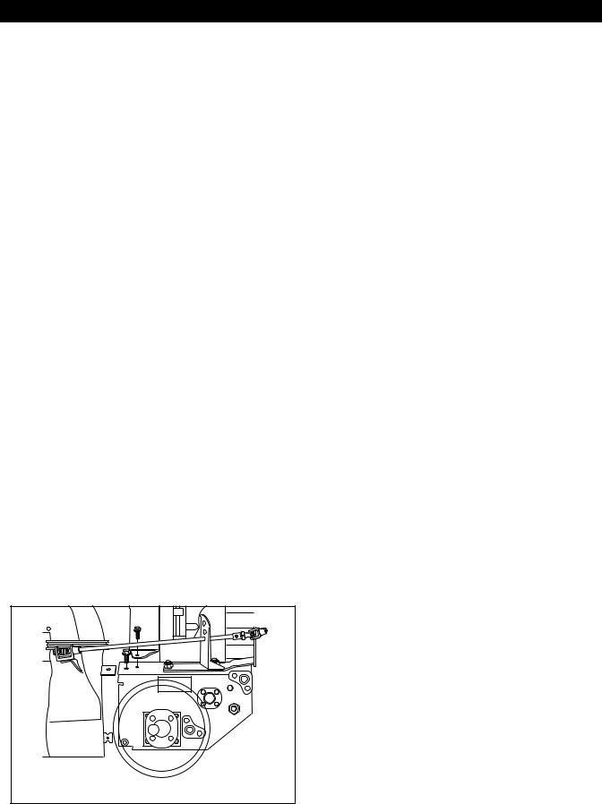
Belt Service Position
To place unit into Belt Service position:
1.Draw gas from gas tank to prevent spilling.
2.Remove the two screws from the belt guard and remove the guard, Figure 2.
3.Extract the pin for the chute crank at the universal connection nearest the chute.
4.Loosen the belt finger guards at the pulley and pivot away from the belts.
5.Remove the attachment drive belt from the engine pulley.
6.To avoid bending the bottom cover plate, tip the unit up on the blower housing. Remove the plate by unscrewing the four bolts.
7.Tip the unit back down and remove the two capscrews securing the housing to the frame.
8.Tip the two halves apart exposing the belts and pulleys.
Upright Service Position
To place unit into Upright Service position:
1.Drain gas from gas tank to prevent spilling.
2.Tip the unit up on the front of the blower housing.
3.Remove the bottom cover plate by unscrewing the four bolts.
|
3 |
4 |
2 |
|
|
1 |
|
|
1. |
Pivot Pin |
|
2. |
Housing Cap Screws |
|
3. |
Belt Guard Cover |
|
4. |
Tapping Screw |
|
|
Figure 2 |
OS0792 |
|
|
|
4.3 FILLING THE FUEL TANK
EXPLOSIVE VAPORS and FLAMMABLE FUEL can result in serious injury or death. Handle fuel with care. ALWAYS use an approved (RED) fuel container.
No Smoking!
No Lighted Materials!
No Open Flame!
Allow engine to cool.
Use caution with fuel. Fuel is very flammable. Keep fuel in a clean and tight container. Keep fuel away from fire or heat. Never put fuel in the fuel tank while the engine is running or hot. Clean up any spilled fuel before starting the engine.
Add fuel to the tank as needed. See your Engine Manual for correct type and grade of fuel.
4 - 11
 Loading...