


TABLE OF CONTENTS
Section 1 - Introduction . . . . . . . . . . . . . . . . . . 1-2
1.1 The Manual . . . . . . . . . . . . . . . . . . . . . . . . . . . . . 1-2
1.2 Service And Replacement Parts . . . . . . . . . . . . . 1-2
1.3 Product Registration. . . . . . . . . . . . . . . . . . . . . . . 1-2
1.4 Unauthorized Replacement Parts . . . . . . . . . . . . 1-2
1.5 Disclaimer. . . . . . . . . . . . . . . . . . . . . . . . . . . . . . . 1-2
1.6 Technical Service Communications . . . . . . . . . . . 1-2
Section 2 - Safety . . . . . . . . . . . . . . . . . . . . . . . . 2-3
2.1 Safety Alerts. . . . . . . . . . . . . . . . . . . . . . . . . . . . . 2-3
2.2 Signal Words . . . . . . . . . . . . . . . . . . . . . . . . . . . . 2-3
2.3 Notations . . . . . . . . . . . . . . . . . . . . . . . . . . . . . . . 2-3
2.4 Practices And Laws . . . . . . . . . . . . . . . . . . . . . . . 2-3
2.5 Required Operator Training . . . . . . . . . . . . . . . . . 2-3
2.6 Preparation. . . . . . . . . . . . . . . . . . . . . . . . . . . . . . 2-3
2.7 Service Position . . . . . . . . . . . . . . . . . . . . . . . . . . 2-3
2.8 Cleaning And Storage . . . . . . . . . . . . . . . . . . . . . 2-3
2.9 Safety Rules. . . . . . . . . . . . . . . . . . . . . . . . . . . . . 2-4
Section 3 - Specifications . . . . . . . . . . . . . . . . . 3-6
Section 4 - General Maintenance
& Adjustments . . . . . . . . . . . . . . . . . . . . . . . 4-8
4.1 Controls And Features . . . . . . . . . . . . . . . . . . . . . 4-8 4.2 Check Fuel Level . . . . . . . . . . . . . . . . . . . . . . . . . 4-9 4.3 General Lubrication . . . . . . . . . . . . . . . . . . . . . . . 4-9 4.4 To Remove 48" Mower Deck . . . . . . . . . . . . . . . 4-10 4.5 To Install 48" Mower Deck . . . . . . . . . . . . . . . . . 4-10 4.6 To Remove 42" Mower Deck . . . . . . . . . . . . . . . 4-10 4.7 To Install 42" Mower Deck . . . . . . . . . . . . . . . . . 4-11 4.8 Mower Height Adjustment . . . . . . . . . . . . . . . . . 4-11 4.9 To Level Mower . . . . . . . . . . . . . . . . . . . . . . . . . 4-12 4.10 Neutral Adjustment (Speed Control) . . . . . . . . 4-13 4.11 Adjusting The Unit To Track Straight . . . . . . . . 4-13 4.12 Anti-scalp Rollers (42" Deck) . . . . . . . . . . . . . . 4-14 4.13 Adjusting The Parking Brake . . . . . . . . . . . . . . 4-15
Section 5 - Engine . . . . . . . . . . . . . . . . . . . . . . 5-16
5.1 Engine Troubleshooting . . . . . . . . . . . . . . . . . . . 5-16
5.2 Checking Engine Oil. . . . . . . . . . . . . . . . . . . . . . 5-17
5.3 Changing Oil. . . . . . . . . . . . . . . . . . . . . . . . . . . . 5-17
5.4 Checking Engine Cooling. . . . . . . . . . . . . . . . . . 5-17
5.5 Cleaning The Air Cleaner. . . . . . . . . . . . . . . . . . 5-17
5.6 Changing The Air Cleaner Element . . . . . . . . . . 5-17
5.7 Inspect Muffler/Spark Arrester . . . . . . . . . . . . . . 5-17
5.8 Replace Spark Plugs . . . . . . . . . . . . . . . . . . . . . 5-17
5.9 Engine Removal . . . . . . . . . . . . . . . . . . . . . . . . . 5-17
5.10 Engine Installation . . . . . . . . . . . . . . . . . . . . . . 5-18
Section 6 - Mower Deck. . . . . . . . . . . . . . . . . . 6-19
6.1 Clutch To Deck Drive Belt Replacement . . . . . . 6-19 6.2 Mower Deck Belt Replacement (48" Deck) . . . . 6-19 6.3 Mower Deck Belt Replacement (42" Deck) . . . . 6-20 6.4 Check Blades . . . . . . . . . . . . . . . . . . . . . . . . . . . 6-20
Section 7 - Drive Train . . . . . . . . . . . . . . . . . . . 7-22
7.1 Hydro Transmission Troubleshooting . . . . . . . . 7-22 7.2 Hydro-Gear Fluid recommendations . . . . . . . . . 7-24 7.3 Hydro-Gear Repair. . . . . . . . . . . . . . . . . . . . . . . 7-24 7.4 Replacement Of Parts . . . . . . . . . . . . . . . . . . . . 7-26 7.5 Oil Fill & Start-up Procedures . . . . . . . . . . . . . . 7-27. 7.6 Hydro-Gear Transmission Removal. . . . . . . . . . 7-28 7.7 Hydro-Gear Transmission Installation . . . . . . . . 7-28
Section 8 - Power Take Off . . . . . . . . . . . . . . . 8-29
8.1 PTO Jackshaft Removal . . . . . . . . . . . . . . . . . . 8-29
8.2 PTO Jackshaft Repair . . . . . . . . . . . . . . . . . . . . 8-29
8.3 PTO Jackshaft Installation . . . . . . . . . . . . . . . . . 8-29
Section 9 - Lift System. . . . . . . . . . . . . . . . . . . 9-30
9.1 Lift System . . . . . . . . . . . . . . . . . . . . . . . . . . . . . 9-30
9.2 Lift System Removal . . . . . . . . . . . . . . . . . . . . . 9-30
Section 10 - Fuel System. . . . . . . . . . . . . . . . 10-31
10.1 Fuel System Troubleshooting . . . . . . . . . . . . 10-31
10.2 Fuel Pump . . . . . . . . . . . . . . . . . . . . . . . . . . . 10-32.
10.3 Fuel System Contamination. . . . . . . . . . . . . . 10-32
10.4 Fuel Tank . . . . . . . . . . . . . . . . . . . . . . . . . . . . 10-32
10.5 Fuel Tank Removal . . . . . . . . . . . . . . . . . . . . 10-32
Section 11 - Electrical . . . . . . . . . . . . . . . . . . 11-33
11.1 Tools. . . . . . . . . . . . . . . . . . . . . . . . . . . . . . . . 11-33
11.2 Electrical Measurements . . . . . . . . . . . . . . . . 11-33
11.3 Battery . . . . . . . . . . . . . . . . . . . . . . . . . . . . . . 11-34
11.4 Switches. . . . . . . . . . . . . . . . . . . . . . . . . . . . . 11-37
11.5 Solenoid And Relays . . . . . . . . . . . . . . . . . . . 11-38
11.6 Lighting Circuits . . . . . . . . . . . . . . . . . . . . . . . 11-39
11.7 Fuses . . . . . . . . . . . . . . . . . . . . . . . . . . . . . . . 11-39
11.8 Diodes And Rectifiers. . . . . . . . . . . . . . . . . . . 11-39
11.9 Electric Clutch . . . . . . . . . . . . . . . . . . . . . . . . 11-39
11.10 EZR Electrical . . . . . . . . . . . . . . . . . . . . . . . 11-39
11.11 Wiring Diagrams. . . . . . . . . . . . . . . . . . . . . . 11-43
11.12 Relays And Switches . . . . . . . . . . . . . . . . . . 11-44
Section 12 - Mower Attachment . . . . . . . . . . 12-45
12.1 42" Mower Spindle Removal . . . . . . . . . . . . . 12-45
12.2 48" Mower Spindle Removal . . . . . . . . . . . . . 12-46
12.3 42" Spindle Repair . . . . . . . . . . . . . . . . . . . . . 12-46
12.4 48" Spindle Repair . . . . . . . . . . . . . . . . . . . . . 12-46
1

SECTION 1 - INTRODUCTION
1.1 THE MANUAL
The purpose of this manual is to provide complete instructions for service, maintenance, disassembly, repair, and installation of the mechanical components for the 915 EZ Rider.
Dealer trained service personnel should use this manual as a supplement to and reminder of the training sessions conducted by the company.
Read all information for servicing a part or system before repair work is started to avoid needless disassembly.
Operation
Before operation of the unit, carefully and completely read manuals supplied with the unit. The contents will provide you with an understanding of safety instructions and controls during normal operation and maintenance.
Safety Messages
For your safety and the safety of others always read, understand, and follow all DANGER, WARNING, and CAUTION messages found in manuals and on safety decals.
Directional Reference
All reference to left, right, front, or rear are given from the operator in the operator position and facing the direction of forward travel.
1.2 SERVICE AND REPLACEMENT PARTS
When ordering publications, replacement parts, or making service inquiries, know the Model and Serial numbers of your unit and engine.
Numbers are located on the product registration form in the unit literature package. They are printed on a serial number label, located on the frame of your unit.
Serial Number
Figure 1
1.3 PRODUCT REGISTRATION
A warranty registration card must be filled out, signed, and returned at time of purchase. This card activates the warranty. Claims meeting requirements during limited warranty period will be honored.
1.4 UNAUTHORIZED REPLACEMENT PARTS
Use only Ariens replacement parts. The replacement of any part on this vehicle with anything other than a Ariens authorized replacement part may adversely affect the performance, durability, or safety of this unit and may void the warranty. Ariens disclaims liability for any claims or damages, whether warranty, property damage, personal injury, or death arising out of the use of unauthorized replacement parts.
1.5 DISCLAIMER
Ariens reserves the right to discontinue, make changes to, and add improvements upon its products at any time without public notice or obligation. The descriptions and specifications contained in this manual were in effect at printing. Equipment described within this manual may be optional. Some illustrations may not be applicable to your unit.
1.6 TECHNICAL SERVICE COMMUNICATIONS
Ariens Technical Service communicates information to the field using Service Letters, Service Bulletins, Product Notices, and Campaigns. Each communication signifies a type of information and priority. The dealer is responsible to carry out the directive provided in the communication. The types of communication are:
Service Letter - General technical information for the dealer. Technical information on how to service the product and product improvements.
Service Bulletin - Notification to update products to resolve certain issues or a notification of a policy change.
Product Notices - Notification of limited product located in a certain region. This is a limited distribution to only those who received the product involved.
Campaigns - Notification of a safety related issue. All products must be updated and are tracked by the factory until all units are corrected.
1 - 2
SECTION 2 - SAFETY
2.1 SAFETY ALERTS
Look for these symbols to point out important safety precautions. They mean:
Attention!
Personal Safety Is Involved!
Become Alert!
Obey The Message!
2.2 SIGNAL WORDS
The safety alert symbol is used in decals on the unit and with proper operation procedures in this manual. They alert you to the existence and relative degree of hazards.
Understand the safety message. It contains important information about personal safety on or near the unit.
DANGER: IMMINENTLY HAZARDOUS SITUATION! If not avoided, WILL RESULT in death or serious injury.
rented or sold, ALWAYS provide the Operator’s Manual and any needed safety training before operation.
2.6 PREPARATION
Before starting any removal of parts, proper preparation is very important for efficient work. A clean work area at the start of each job will allow you to perform service repairs easily and quickly.
To reduce the incidence of misplaced tools or parts, place removed components with all attaching hardware in the disassembly order on a clean work surface. Organization is a key part of proper reassembly.
Tools, instruments, and parts needed for the job should be gathered before work is started. Interrupting a job to locate tools or parts is a needless delay. A list of required special tools has been included in this manual.
CAUTION: Remove enough fuel so that no spillage will occur. Remove battery to prevent spillage of electrolyte.
WARNING: POTENTIALLY HAZARDOUS SITUATION! If not avoided, COULD RESULT in death or serious injury.
CAUTION: POTENTIALLY HAZARDOUS SITUATION! If not avoided, MAY RESULT in minor or moderate injury. It may also be used to alert against unsafe practices.
2.3 NOTATIONS
NOTE: General reference information for proper operation and maintenance practices.
IMPORTANT: Specific procedures or information required to prevent damage to unit or attachment.
2.4 PRACTICES AND LAWS
Practice usual and customary safe working precautions, for the benefit of yourself and others. Understand and follow all safety messages. Be alert to unsafe conditions and the possibility of minor, moderate, or serious injury or death. Learn applicable rules and laws in your area.
2.5 REQUIRED OPERATOR TRAINING
Original purchaser of this unit was instructed by the seller on safe and proper operation. If unit is to be used by someone other than original purchaser; loaned,
2.7 SERVICE POSITION
WARNING: Always block wheels and know that jack stands or blocks used are stable, strong, or secure and will hold the weight of the unit during maintenance.
To ensure the unit is positioned in the proper service position:
1.Place jack stands under rear transaxles only.
2.If jacks are not available, place support blocks under both transaxles at the rear of unit.
2.8 CLEANING AND STORAGE
IMPORTANT: Never spray unit with water or store unit outdoors to help prevent sealed bearing rust or corrosion. Water can seep into sealed bearings and reduce component life. Bearings are sealed against dirt and debris only.
A unit that is excessively dirty should be cleaned before work starts. Cleaning will occasionally uncover trouble sources. Dirt and abrasive dust reduce the efficient work life of parts and can lead to costly replacement.
When taking unit out of extended storage:
1.Check for any damage or loose parts. Repair replace, or tighten hardware before operation.
2 - 3
2.If a preservative fluid was used in fuel tank, drain and discard. Fill fuel tank with fresh new fuel.
2.9 SAFETY RULES
Walk Around Inspection
Complete a walk around inspection of unit and work area to understand:
•Work area.
•Your unit.
•All safety decals.
Work Area
ALWAYS check overhead and side clearances carefully before operation. ALWAYS be aware of traffic when operating along streets or curbs.
ALWAYS keep hands and feet within the limits of the unit.
Keep children, people, and animals away. Keep children out of work area and under watchful care of a responsible adult.
Keep area of operation clear of all toys, pets, and debris. Objects can cause vehicle instability and injury.
Check for weak spots on dock, ramps or floors. Avoid uneven work areas and rough terrain. Stay alert for hidden hazards.
DO NOT run engine in an enclosed area. Always provide good ventilation.
Unit
ALWAYS keep protective structures, guards, and panels in good condition, in place and securely fastened. NEVER modify or remove safety devices.
Check Safety Interlock System for proper operation daily (see Operation section). Do not operate unless system operates properly.
Operation
Understand:
•How to operate all controls
•The functions of all controls
•How to STOP in an Emergency
•Speed ranges
Do not operate any of the control levers or power takeoff unless both feet are resting on the platform.
DO NOT travel at too fast a rate. DO NOT change engine governor settings or over-speed engine.
Always back up slowly. Always look down and behind before and while backing.
Never leave a running unit unattended. ALWAYS shut off power take off, lower throttle setting, and stop engine before leaving unit. ALWAYS remove key to prevent unauthorized use.
Never carry passengers on any part of unit.
Avoid uneven and rough terrain. DO NOT operate near drop offs, ditches, or embankments. Unit can suddenly turn over if a wheel is over the edge of a cliff or ditch, or if an edge caves in.
If tires lose traction, turn off power take off and proceed slowly straight down slope. Avoid wet surfaces.
Avoid parking on a slope. If necessary, use wheel chocks.
DO NOT leave unit unattended on a slope. ALWAYS use wheel chocks when leaving unit.
ALWAYS operate unit in good visibility and light.
Fuel is highly flammable and its vapors can explode. Use ONLY approved fuel containers.
NO Smoking!
NO Sparks!
NO Flames!
Allow engine to cool before servicing.
NEVER fill fuel tank when engine is running, hot, or unit is indoors.
Abnormal Vibrations are a warning of trouble. Striking a foreign object can damage unit. Immediately stop unit and engine. Remove key and wait for all moving parts to stop. Remove wire from spark plug. Inspect unit and make any necessary repairs before restart.
Hazardous Slopes
DO NOT operate on steep slopes. Avoid operating on slopes. When you must operate on a slope, travel up and down the slope. Never operate across a slope.
Never operate on a slope greater than 10 degrees.
Child Safety
NEVER allow children to operate or play on or near unit. Be alert and shut off unit if children enter area.
Personal Safety
Read and obey all warning, caution, and instructions on the unit and in provided manuals.
•Only trained adults may operate unit.
•Training includes actual operation.
•Clearly understand instructions.
•Be alert! Conditions can change.
NEVER operate unit after or during the use of medication, drugs or alcohol. Safe operation requires your complete and unimpaired attention at all times.
NEVER allow anyone to operate the unit when their alertness or coordination is impaired.
DO NOT operate unit without wearing adequate outer garments. Wear adequate safety gear and protective gloves. Wear proper footwear to improve footing on slippery surfaces.
Protect eyes, face, and head from objects that may be thrown from unit. Wear appropriate hearing protection.
2 - 4
Avoid Sharp Edges. Sharp edges can cut. Moving parts can cut or amputate fingers or a hand. Wear gloves to service unit when handling sharp edges.
ALWAYS keep hands away from any pinch points.
ALWAYS keep hands and feet away from all moving parts during operation. Moving parts can cut off body parts.
DO NOT touch unit parts which might be hot from operation. Allow parts to cool before attempting to maintain, adjust, or service.
Controls
Come to a complete stop before reversing.
Never jerk the control levers. Always use a steady even action to achieve smooth control.
Always be aware of obstructions that may cause injury to operator or damage to the unit.
Maintenance
ALWAYS maintain unit in safe operating condition. Damaged or worn out muffler can cause fire or explosion.
Check the conditions of the unit at the end of each day and repair any damage or defects.
ALWAYS block wheels and know all jack stands are strong and secure and will hold weight of unit during maintenance.
Keep nuts and bolts tight and keep equipment in safe operating conditions.
Before maintenance, adjustments, or service (except where specifically recommended), shut off engine.
Allow hot parts to cool.
Keep unit free of dirt, stones, and other debris. Clean up oil or fuel spills.
Storage
DO NOT store unit inside a building with fuel in the fuel tank where any ignition sources are present. Allow unit to cool completely.
ALWAYS clean unit before extended storage. See Engine Manual for proper storage.
Battery
Avoid Electric Shock. DO NOT reverse battery connections.
Explosive Gases! Poisonous battery fluid contains sulfuric acid and its contact with skin, eyes, or clothing can cause severe burns.
No flames. No sparks. No smoking near battery.
Always wear safety glasses and protective gear near battery.
DO NOT TIP battery beyond a 45o angle in any direction.
ALWAYS KEEP BATTERIES OUT OF REACH of children.
Transport
Use extra care when loading or unloading unit onto trailer or truck. Secure unit chassis to transport vehicle. NEVER secure from rods or linkages that could be damaged.
DO NOT transport with attachment in raised position.
Lower attachment when unit is parked or stored unless a positive mechanical lock is used.
Attachments and Accessories
Use only attachments or accessories designed for your unit.
2 - 5

SECTION 3 - SPECIFICATIONS
Model Number |
915304 |
915305 |
Model |
EZR 1742 |
EZR 2048 |
Engine |
17.0 HP OHV |
20.0 HP OHV |
|
|
|
Manufacture |
Briggs & Stratton |
Briggs & Stratton |
|
|
|
Fuel & Capacity - gal (L) |
Unleaded 3.5 (13.3) |
Unleaded 3.5 (13.3) |
|
|
|
Idle RPM |
1800 RPM |
1800 RPM |
|
|
|
Governed RPM |
3000 RPM |
3150 RPM |
|
|
|
Crank Case Capacity (Oil Filter) - oz (L) |
48 (1.66) |
64 (1.9) |
|
|
|
Air Cleaner |
Paper Element |
Paper Element |
|
Foam Precleaner |
Foam Precleaner |
|
|
|
Charging Capacity |
9 Amp Unregulated |
9 Amp Unregulated |
|
|
|
Fuel Filter |
75 Micron |
60 Micron |
|
|
|
Engine Oil |
30W over 32oF (0oC) |
30W over 32oF (0oC) |
|
5W30 |
5W30 |
|
below 32oF (0oC) |
below 32oF (0oC) |
Spark Plug Gap |
.030 Champion RC12YC |
.030 Champion RC12YC |
|
|
|
Transmission |
Hydro-Gear |
Hydro-Gear |
|
|
|
Speed Forward Max. |
0-5.2 (8.4) |
0-5.2 (8.4) |
mph (kph) |
|
|
|
|
|
Reverse Max. - mph (kph) |
0-3.6 (5.8) |
0-3.6 (5.8) |
|
|
|
Transmission Lube |
20W50 |
20W50 |
|
|
|
Drive Clutch |
N/A |
N/A |
|
|
|
Allowable Added Weight |
N/A |
N/A |
|
|
|
Rear Axle Maximum Load |
N/A |
N/A |
|
|
|
Tire Pressure With Loads |
|
|
|
|
|
Front/Rear-Light psi (kN/m2) |
15-20 (103-138) |
15-20 (103-138) |
Medium |
10-12 (83-103) |
10-12 (83-103) |
|
|
|
Heavy |
10-12 (83-103) |
10-12 (83-103) |
|
|
|
Lift System |
Spring Assist |
Spring Assist |
|
|
|
Power Take Off |
Electric |
Electric |
|
|
|
Battery |
12 Volt 255 C.C.A. |
12 Volt 255 C.C.A. |
|
|
|
Hour Meter |
Optional (71501200) |
Optional (71501200) |
|
|
|
Seat |
High Back |
High Back |
|
|
|
Brakes |
Parking |
Parking |
|
|
|
Steering |
Castor Wheels |
Castor Wheels |
|
|
|
Turning Radius |
0" |
0" |
|
|
|
Tire Size |
|
|
|
|
|
Front |
11.0x4.00-5 |
11.0x4.00-5 |
|
|
|
Rear |
18x8.50-8 |
18x8.50-8 |
|
|
|
Diagnostic Lights |
N/A |
N/A |
|
|
|
Attachments: |
|
|
|
|
|
Mower Pan - in (cm) |
42 (106.7) |
48 (122) |
|
|
|
Bagger 2 Bucket |
815008 |
71501900 |
|
|
|
Sno-Thro |
N/A |
N/A |
|
|
|
Dozer Blade |
815006 |
815006 |
|
|
|
Mulching Kit |
71501300 |
N/A |
|
|
|
Headlight Kit |
71501100 |
71501100 |
|
|
|
Front Weight Kit |
71500300 |
71500300 |
|
|
|
Rear Weight Kit |
71500700 |
71500700 |
|
|
|
Tire Chain Kit |
71501000 |
71501000 |
|
|
|
Bumper Kit |
71501500 |
71501500 |
|
|
|
3 - 6
Model Number |
915013 |
915014 |
Model |
EZR 1742 |
EZR 2048 |
Engine |
17.0 HP OHV |
20.0 HP OHV |
|
|
|
Manufacture |
Briggs & Stratton |
Briggs & Stratton |
|
|
|
Fuel & Capacity - gal (L) |
Unleaded 3.5 (13.3) |
Unleaded 3.5 (13.3) |
|
|
|
Idle RPM |
1800 RPM |
1800 RPM |
|
|
|
Governed RPM |
3300 RPM |
3250 RPM |
|
|
|
Crank Case Capacity (Oil Filter) - oz (L) |
48 (1.4) |
64 (1.9) |
|
|
|
Air Cleaner |
Paper Element |
Paper Element |
|
Foam Precleaner |
Foam Precleaner |
|
|
|
Charging Capacity |
9 Amp Unregulated |
9 Amp Unregulated |
|
|
|
Fuel Filter |
75 Micron |
60 Micron |
|
|
|
Engine Oil |
30W over 32oF (0oC) |
30W over 32oF(0oC) |
|
5W30 below 32oF (0oC) |
5W30 below 32oF (0oC) |
Spark Plug Gap |
.030 Champion RC12YC |
.030 Champion RC12YC |
|
|
|
Transmission |
Hydro-Gear |
Hydro-Gear |
|
|
|
Speed Forward Max. mph (kph) |
0 - 5.2 (0 - 8.4) |
0 - 5.2 (0 - 8.4) |
|
|
|
Reverse Max. - mph (kph) |
0 - 3.6 (0 - 5.8) |
0 - 3.6 (0 - 5.8) |
|
|
|
Transmission Lube |
20 W 50 |
20 W 50 |
|
|
|
Drive Clutch |
N/A |
N/A |
|
|
|
Allowable Added Weight |
N/A |
N/A |
|
|
|
Rear Axle Maximum Load |
N/A |
N/A |
|
|
|
Tire Pressure With Loads |
|
|
|
|
|
Front/Rear-Light psi (kN/m2) |
15-20 (103-138) |
15-20 (103-138) |
Medium |
10-12 (83-103) |
10-12 (83-103) |
|
|
|
Heavy |
10-12 (83-103) |
10-12 (83-103) |
|
|
|
Lift System |
Spring Assist |
Spring Assist |
|
|
|
Power Take Off |
Electric |
Electric |
|
|
|
Battery |
12 Volt 255 C.C.A |
12 Volt 290 C.C.A. |
|
|
|
Hour Meter |
Optional (715012) |
Optional (71500100) |
|
|
|
Seat |
High Back |
High Back |
|
|
|
Brakes |
Parking |
Parking |
|
|
|
Steering |
Castor Wheels |
Castor Wheels |
|
|
|
Turning Radius |
0" |
0" |
|
|
|
Tire Size |
|
|
|
|
|
Front |
11.0x4.00-5 |
11.0x4.00-5 |
|
|
|
Rear |
18x8.50-8 |
18x8.50-8 |
|
|
|
Diagnostic Lights |
N/A |
N/A |
|
|
|
Attachments: |
|
|
|
|
|
Mower Pan - in (cm) |
42 (106.7) |
48 (122) |
|
|
|
Bagger 2 Bucket |
815008 |
71501900 |
|
|
|
Sno-Thro |
815003 |
815003 |
|
|
|
Dozer Blade |
815006 |
815006 |
|
|
|
Mulching Kit |
71501300 |
N/A |
|
|
|
Headlight Kit |
71501100 |
71501100 |
|
|
|
Front Weight Kit |
71500300 |
71500300 |
|
|
|
Rear Weight Kit |
71500700 |
71500700 |
|
|
|
Tire Chain Kit |
71501000 |
71501000 |
|
|
|
Bumper Kit |
71501500 |
71501500 |
|
|
|
3 - 7

SECTION 4 - GENERAL MAINTENANCE & ADJUSTMENTS
4.1 CONTROLS AND FEATURES
11
 1
1
 2
2
7 10
 8
8
 9
9
15
14
12
OE0680
13 
3 
6
5
 4
4
OE0860
1. |
Steering Control Levers |
9. |
Foot Rest |
2. |
Battery Compartment |
10. |
Fuel Level Indicator Window |
3. |
Ignition Switch |
11. |
Fuel Tank Cap |
4. |
Power Take Off (PTO) |
12. |
Discharge Chute |
5. |
Throttle Control (Throttle/Choke Control) |
13. |
Anti-Scalp Rollers |
6. |
Choke Control (2048) |
14. |
Belt Cover |
7. |
Parking Brake Lever |
15. |
Locking Lever |
8. |
Attachment Lift Lever |
|
|
Figure 2
4 - 8
4.2 CHECK FUEL LEVEL
The fuel level is shown through a window in the control panel next to the parking brake.
WARNING: Fuel is highly flammable and its vapors are explosive. Handle with care.
NO smoking, NO sparks, NO flames.
Refer to Engine Manual for proper fuel.
To add fuel to the fuel tank:
1.ALWAYS place unit in open or well ventilated area.
2.Stop engine and allow to cool for two minutes.
3.Clean the fuel cap and the area around the fuel cap to prevent dirt from entering the fuel tank.
 1
1
2
1.Fuel Cap
2.Fuel Level Window
Figure 3
OE0690
4.Remove the cap from the fuel tank.
5.Fill the fuel tank with the proper grade of fuel as recommended by the engine manufacturer. Do not spill any fuel.
6.Replace the cap on the fuel tank and tighten.
7.ALWAYS clean up any spilled fuel before starting the engine.
4.3 GENERAL LUBRICATION
Refer to Figure 4 for the locations of the grease fittings on the unit and the intervals at which to grease them.
All grease fittings should be greased at 25-hour intervals. Clean and inspect parts and replace as required.
1.Clean the fittings before attaching the grease gun.
2.Thoroughly clean and dry all parts with a suitable solvent.
3.Check all parts for wear and damage.
4.Replace all parts that are worn or damaged.
5.Use Sten Mix Hi-Temp Grease (a moly-lithium grease) or equivalent. Add grease until it appears at the ends of the bearing or ends of the shaft.
6.Every 25 hours apply motor oil to all pin connections, pivots points and areas where sliding occurs.
Front
Mower Drive Idler
Clutch Shaft Idler
Transaxle Idler
Back OE0330
OE0700
Figure 4
CAUTION: Before performing any service or adjustments:
•Turn PTO switch "OFF".
•Park mower on a hard, flat, level surface.
•Place steering control levers in neutral lock (fully outward) position.
•Set parking brake.
•Turn ignition switch "OFF" and remove key.
•Wait for blades and all moving parts to stop.
4 - 9
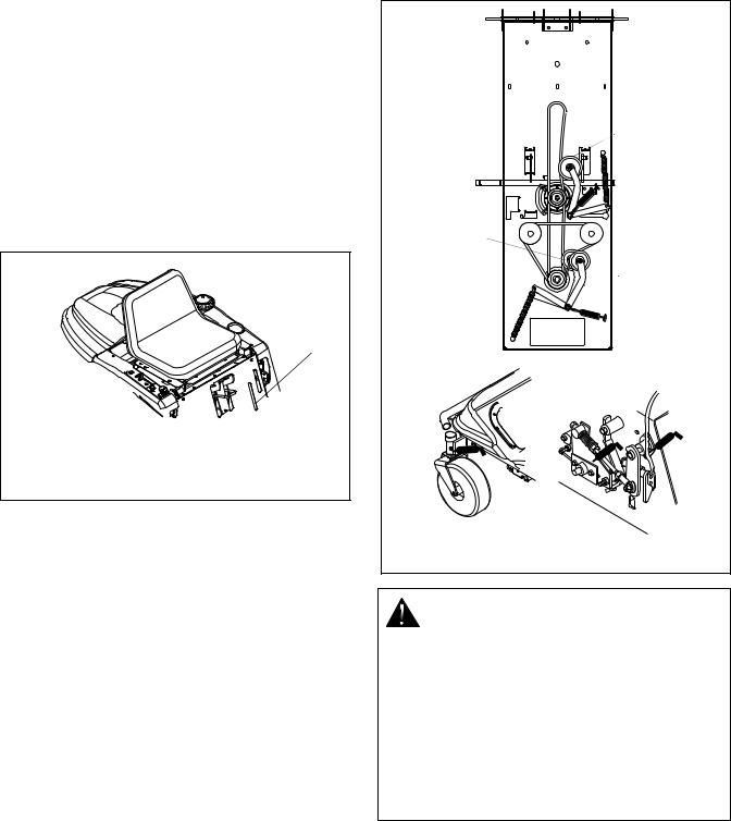
4.4 TO REMOVE 48" MOWER DECK
1.Turn off engine, engage parking brake and allow hot parts to cool.
2.Place center deck lift handle in lowest (1) position.
WARNING: AVOID injury from stored energy in lift assist spring. DO NOT unlock attachment lift lever with mower deck removed. ALWAYS engage Attachment Lift Lever Lock when removing mower deck.
3.Engage attachment lift lock. Pull handle out and rotate down 90o. Handle will spring into locked position.
Disengaged |
Engaged |
OE0730 |
OE0720 |
Figure 5
4.Disconnect mower belt idler spring from bolt under frame.
5.Remove deck belt from mower pulley and electric clutch.
6.Remove hair pins and washers holding height adjusters to lift arm, and unhook height adjusters from lift arm.
7.Unhook the rear hangers from the holes in the bottom of the frame.
8.Remove cotter pin and washer from end of front pin.
9.Slide front pin out to release front lift arms from frame.
10.Slide mower from under tractor. Mower is easier to remove from the right side of the tractor.
|
|
4 |
5 |
|
|
|
|
|
2 |
3 |
|
|
|
6 |
|
|
1 |
|
|
|
|
|
|
1. |
Front Pin |
4. |
Height Adjuster |
2. |
Front Lift Arm |
5. |
Lift Lever Hook |
3. |
Rear Hanger |
6. |
Hair Pin |
|
|
|
OE170 |
|
|
Figure 6 |
|
4.5 TO INSTALL 48" MOWER DECK
1.To center deck lift handle should be in the lowest
(1) position with the attachment lift lock engaged.
WARNING: AVOID injury from stored energy in lift assist spring. DO NOT unlock attachment lift lever with mower deck removed. ALWAYS engage Attachment Lift Lever Lock when removing mower deck.
2.Push mower under unit. Mower is easier to push in from right side of the tractor.
3.Slide a washer down to tabbed end of front pin.
4.Align holes in front lift arms with slots at front of frame and slide front pin through arms and frame.
5.Secure front pin with washer and cotter pin.
6.Hook rear hanger into the holes in the bottom of the frame on both sides.
7.Secure rear hangers with hair pins.
8.Hook the height adjusters onto the lift arm.
9.Secure height adjusters with washers and hair pins.
10.Install deck belt onto mower pulley and electric clutch.
11.Connect mower belt idler spring to bolt under frame.
12.Disengage attachment lift lock.
4.6 TO REMOVE 42" MOWER DECK
1.Turn off engine, engage parking brake and allow hot parts to cool.
2.Place center deck lift handle in lowest (1) position.
4 - 10
WARNING: AVOID injury from stored energy in lift assist spring. DO NOT unlock attachment lift lever with mower deck removed. ALWAYS engage Attachment Lift Lever Lock when removing mower deck.
3.Engage attachment lift lock. Pull handle out and rotate down 90o.
Disengaged |
Engaged |
OE0730 |
OE0720 |
Figure 7
4.Loosen nut on rod link at front of tractor. It is not necessary to remove it entirely.
5.Release rod link locking brackets from rod link at front of deck.
6.Remove deck belt from drive pulley.
7.Remove hair pins and clevis pins from rear deck link.
8.Remove hair pins and washers from deck lift.
9.Pivot right front wheel to allow deck to slide past.
10.Slide mower from under tractor. Mower is easier to remove from the right side of the tractor.
1 |
2 |
3 |
4 |
5 |
|
|
6
|
8 |
|
7 |
1. |
Rod Link Lock |
5. |
Mower Frame |
|
Brackets |
6. |
Idler |
2. |
Drive Pulley |
7. |
Adjuster Link Washer |
3. |
Belt |
|
& Hair PIn |
4. |
Rear Deck Link Hair |
8. |
Rod Link Nut |
|
Pin & Clevis Pin |
|
|
|
|
Figure 8 |
OE0720 |
4.7 TO INSTALL 42" MOWER DECK
1.The center deck lift handle should be in the lowest
(1) position with the attachment lift lock engaged.
WARNING: AVOID injury from stored energy in lift assist spring. DO NOT unlock attachment lift lever with mower deck removed. ALWAYS engage Attachment Lift Lever Lock when removing mower deck.
2.Push mower deck under tractor from right side of unit.
3.Attach deck lift with washers and hair pins.
4.Attach rear deck link with clevis pins and hair pins.
5.Place drive belt around drive pulley, idler and clutch pulley.
6.Place rod link in holding brackets at front of deck and engage rod link locking brackets.
7.Tighten nut on end of rod link until it is snug.
8.Disengage attachment lift lock.
4.8 MOWER HEIGHT ADJUSTMENT
Cutting Height Settings Chart
Setting |
Cut grass length |
|
|
|
|
1 |
1-3/8" (35mm) |
|
|
2 |
2" (51 mm) |
|
|
3 |
2-3/4" (70 mm) |
|
|
4 |
3-1/2" (89 mm) |
|
|
5 |
4-3/8" (111 mm) |
|
|
To Adjust 48" Deck:
3
1 |
4 |
2
1. |
Adjusting Tab |
3. |
Height Adjuster |
2. |
Carriage Bolt Flange |
4. |
Height Adjuster Nut |
|
Locknut |
|
|
|
Figure 9 |
Ot0770 |
|
4 - 11
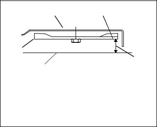
1.To adjust mower height, place mower in the number three (3) position.
2.Loosen height adjuster nuts.
3.Remove hair pins and washers holding height adjusters to lift arm and unhook height adjusters from lift arm.
4.Turn height adjusters equally clockwise to raise mower, or equally counterclockwise to lower mower. Adjust for a height of 2-3/4" from ground to blade tip.
NOTE: Proper blade pitch is when the blade tip, measured from the bottom surface, is 1/8" to 1/4" lower at front of mower deck than when same tip is at rear of mower deck.
5.Hook height adjusters onto lift arm and check for correct height. If not correct, continue to turn height adjusters until height is correct.
6.Tighten height adjuster nuts.
7.Secure height adjusters with washers and hair pins.
To Adjust 42" Deck
1.Place mower in the number three (3) position.
2.Place anti-scalp rollers in highest position so they do not touch the ground during adjustment.
3.Turn the nuts on the bottom of the adjusters equally until the blade tips are 2-3/4" from the ground.
NOTE: Proper blade pitch is when the blade tip, measured from the bottom surface, is 1/8" to 1/4" lower at front of mower deck than when same tip is at rear of mower deck.
4.Reset anti-scalp rollers to match desired attachment position.
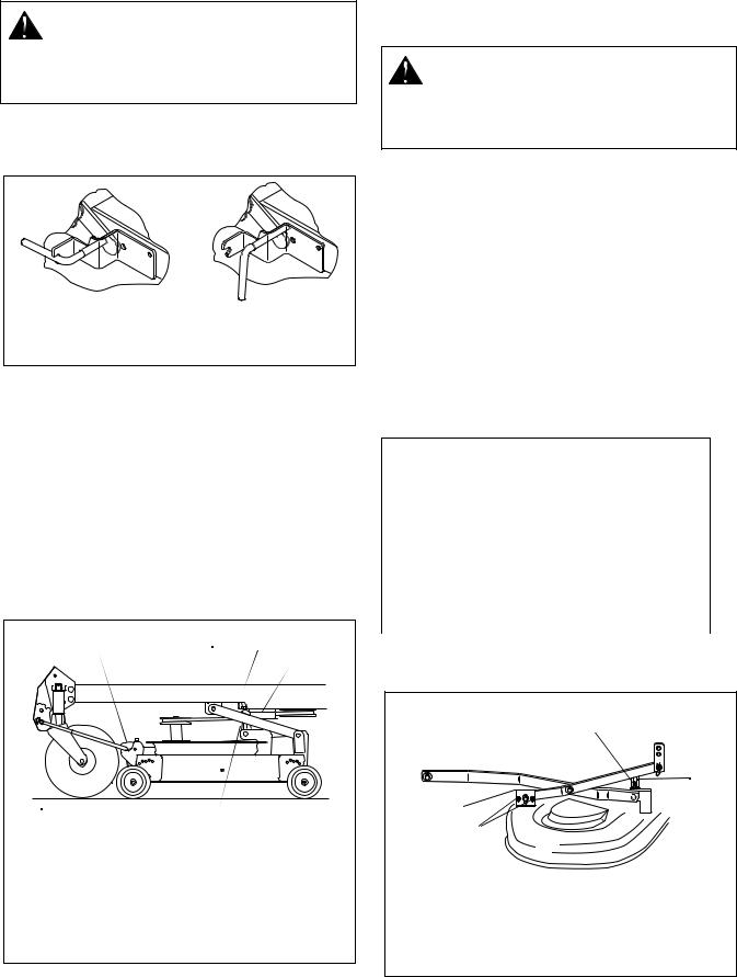
4.9 TO LEVEL MOWER
Adjust the mower while tractor is parked on level ground or driveway. Make sure tires are properly inflated (See Specifications). If tires are overinflated or underinflated, you can not properly adjust your mower.
To Check Side to Side Level
1.Position unit on a smooth, flat, level surface. Set proper tire pressure.
2.Position blade(s) side to side; measure distance of
blade tips to floor at right and left side of mower pan. Rotate blade(s) 180o and check again. The measurement should be equal within 1/16 inch side to side.
NOTE: To make measuring distance from blade to ground easier, obtain a wood block about 1 inch square by 5 inches long. Wrap the entire block with masking tape. Hold block in vertical position with its lower tip on ground. Push block against cutting edge of blade so as to make a mark on tape. Pull the block away and with a ruler measure the distance from lower block tip to mark.
1 |
2 |
5 
 3
3
4 
(Shown from front) |
|
|
|
1. |
Mower Deck |
4. |
Ground Level |
2. |
Blade |
5. |
Cutting Height |
3. |
Front Blade Height |
|
|
OT0860
Figure 10
To Adjust Side to Side Level (48" Deck)
1.Loosen height adjuster nuts.
2.Remove hair pins and washers holding height adjusters to lift arm and unhook height adjusters from lift arm.
3.On low side: Turn height adjuster nut clockwise on low side of mower pan to raise low side. Raise low side one half the measured difference in height between the low side and the high side. On high side: Turn height adjuster nut counterclockwise to lower high side the other one half of the height difference.
4.Hook height adjusters onto lift arm and check side to side level. If not level, continue to turn height adjusters until deck is level side to side.
5.Tighten height adjuster nuts.
6.Secure height adjusters with washers and hair pins.
To Adjust Side to Side Level (42" Deck)
1.Place anti-scalp rollers in highest position so they do not touch the ground during adjustment.
2.Put height adjustment lever in the number three (3) position.
3.With a 1/2" open-end wrench, adjust the nuts on the bottom of the adjuster link until each end of the blade is 2-3/4" from the ground within 1/16".
4.Reset anti-scalp rollers to match desired attachment position.
4 - 12
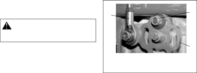
4.10 NEUTRAL ADJUSTMENT (SPEED CONTROL)
1.Stop the engine. Remove the ignition key. Push the PTO knob into the "OFF" position.
CAUTION: PREVENT personal injury! ALWAYS MAKE CERTAIN that jack(s) or blocks used are stable, strong and will support the weight of the unit.
2.Place jack(s) under rear transaxles only. If jack(s) are not available, place support blocks under both transaxles at the rear of the unit to raise the rear wheels off the ground.
3.Remove side shrouds.
4.Place a weight on the seat to close the seat switch. Start the engine and run it at part throttle.
5.Remove the connecting linkage from the flange bushing, Figure 12.
6.Rotate flange bushing until the wheel stops rotating.
7.Lock the flange bushing in place by tightening the lock nut.
8.Adjust the connecting rod length and reattach it to the flange.
9.Loosen the lock nut and test by moving the steering control levers.
10.Repeat procedure for the other side of the unit.
11.Reinstall side shrouds.
If the drive cannot be adjusted to neutral using the above procedure, the link to the flange on the transaxle can be adjusted.
1.With the rear of the unit jacked up and supported, remove the connecting linkage at the flange (Figure 11).
2.Place a weight on the seat and start the engine. Run it at part throttle.
3.Rotate the flange until the wheel stops turning and tighten the lock nut.
4.Shut off the engine.
5.Loosen the lock nut on the connecting linkage and adjust the rod end to match the hole in the flange.
6.Reattach the connecting linkage and tighten the lock nut to the rod end.
7.Loosen the flange lock nut and test.
2
1
 3
3
1. |
Connecting Linkage |
3. Flange |
2. |
Lock Nut |
|
Figure 11
4.11 ADJUSTING THE UNIT TO TRACK STRAIGHT
The primary reason the unit may not track straight is incorrect or unbalanced tire air pressure.
1.First, check and adjust the tire pressure.
2.With tire pressures equal and the rear of the unit on jack stands, check the circumference of the tire. If one tire is larger than the other, increase pressure in the small tire and/or decrease pressure in the larger tire.
3.With both tires the same size, set the control handles. The roller bearing on the speed control arm must be in the neutral position on the neutral detent strap.
4.Adjust upper control arm linkage until the control handles will enter the neutral switch slot and activate the neutral switches.
5.Tighten locking nuts on the control linkage.
6.Disconnect linkage from the transmission, loosen two cap screws in the speed control arm and position pump weldment in the horizontal position and tighten cap screws.
7.Start unit and by hand adjust the transmission control cam until neutral is found.
8.Tighten a transmission locking nut.
9.Stop engine.
10.Set transmission linkage rod, then line up with hole in control cam and install and tighten attachment ball.
11.Loosen the transmission control locking nut.
12.Start unit and check tracking.
4 - 13
|
1 |
|
|
|
4 |
|
|
|
2 |
|
|
|
3 |
|
|
|
2 |
|
|
1. |
Eccentric |
3. |
Flange Bushing |
2. |
Locknuts and Bolts |
4. |
Speed Control Arm |
Figure 12
OE0082
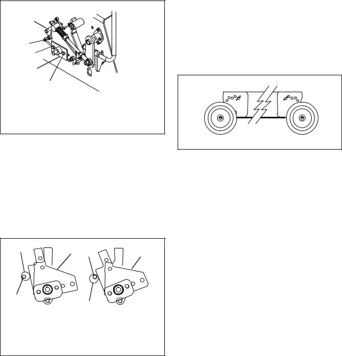
For final tracking adjustment:
1.Remove side shrouds. Set aside.
2.Loosen bolts which attach the eccentric to the seat support. Do not remove the bolts.
3.Rotate eccentric to adjust the travel of the speed control arm. The thicker portion of the eccentric shortens the distance the steering control lever will travel forward. The thinner portion of the eccentric lengthens the distance the steering control lever will travel forward.
1 |
3 |
1 |
3 |
|
|
2 |
|
|
2 |
Shorter Travel |
Longer Travel |
|
1.Eccentric
2.Bolt
3.Speed Control Arm
Figure 13 |
OE0850 |
4.Adjust the rotation of the eccentrics on one or both sides of the unit so that the steering control levers align in the full forward position.
5.Tighten the eccentric’s bolts.
6.Reinstall the side shrouds.
4.12 ANTI-SCALP ROLLERS (42" DECK)
Rollers are intended to prevent lawn scalping, not to control cutting height.
For proper operation, adjust the anti-scalp rollers to the same or higher than mower cutting height. For example, when mowing at the number three (3) height position, the anti-scalp rollers must be adjusted to their number three (3) or higher position.
4 |
3 2 1 |
1 2 3 |
4 |
5 |
|
|
5 |
Figure 14 |
OE0740 |
4 - 14
 Loading...