


PEGASO 650 STRADA-TRAIL
Table of contents
 Loading...
8104936
PEGASO 650 STRADA - TRAIL
2
use and maintenance Pegaso 650 I.E. STRADA - TRAIL
© 2005 Piaggio & C. S.p.A. - Noale (VE)
First edition: September 2005
Reprint:
Produced and printed by:
VALLEY FORGE DECA
Ravenna , Modena, Torino
DECA S.r.l.
Sede Legale ed Amministrativa
Via Vincenzo Giardini, 11
48022 Lugo (RA) - Italia
Tel. +39 - 0545 216611
Fax +39 - 0545 216610
E-mail: deca@vftis.spx.com
www.vftis.com
on behalf of:
Piaggio & C. S.p.A.
via G. Galilei, 1 - 30033 Noale (VE) - Italia
Tel. +39 - 041 58 29 111
Fax +39 - 041 44 10 54
www.aprilia.com
SAFETY WARNINGS
The following precautionary warnings are
used throughout this manual in order to
convey the following messages:
Safety warning. When you find this
symbol on the vehicle or in the
manual, be careful to the potential risk
of personal injury. Non-compliance with
the indications given in the messages
preceded by this symbol may result in
grave risks for your and other people’s
safety and for the vehicle!
WARNING
Indicates a potential hazard which may
result in serious injury or even death.
CAUTION
Indicates a potential hazard which may
result in minor personal injury or
damage to the vehicle.
NOTE The word “NOTE” in this manual
precedes important information or
instructions.
TECHNICAL INFORMATION
The operations preceded by this
symbol must be repeated also on
the opposite side of the vehicle.
If not expressly indicated otherwise, for the
reassembly of the units repeat the
disassembly operations in reverse order.
The terms “right” and “left” are referred to
the rider seated on the vehicle in the
normal riding position.
WARNINGS - PRECAUTIONS -
GENERAL ADVICE
Before starting the engine, carefully read
this manual and in particular the section
“SAFE DRIVE”.
Your and other people’s safety depends
not only on your quickness of reflexes and
on your agility, but also on what you know
about the vehicle, on its efficiency and on
your knowledge of the basic information for
“SAFE DRIVE”. Therefore, get a thorough
knowledge of the vehicle, in such a way as
to be able to ride in the traffic safely.
NOTE Keep a stock of one bulb per type
with the vehicle (see technical data).
H
3
use and maintenance Pegaso 650 I.E. STRADA - TRAIL
NOTE This manual must be considered
as an integral part of the vehicle and must
always accompany it, even in case of
resale.
aprilia has carried out this manual with
the maximum attention, in order to supply
the user with correct and updated
information. However, since aprilia
constantly improves the design of its
products, there may be slight
discrepancies between the characteristics
of your vehicle and those described in this
manual. For any clarification concerning
the information contained in this manual,
do not hesitate to contact an aprilia
Authorised Dealer.
For inspections and repair operations not
expressly described in this publication, for
the purchase of aprilia genuine spare
parts, accessories and other products, as
well as for specific advice, contact
exclusively aprilia Authorised Dealers and
Service Centres, which guarantee prompt
and accurate assistance.
Thank you for choosing aprilia. We wish
you a nice ride.
All rights as to electronic storage,
reproduction and total or partial adaptation,
with any means, are reserved for all
Countries.
NOTE In some countries the
antipollution and noise regulations in force
require periodical inspections.
The user of the vehicle in these countries
must:
– contact an aprilia Authorised Dealer
to have the non-homologated
components replaced with others
homologated for use in the country in
question;
– carry out the required periodical
inspections.
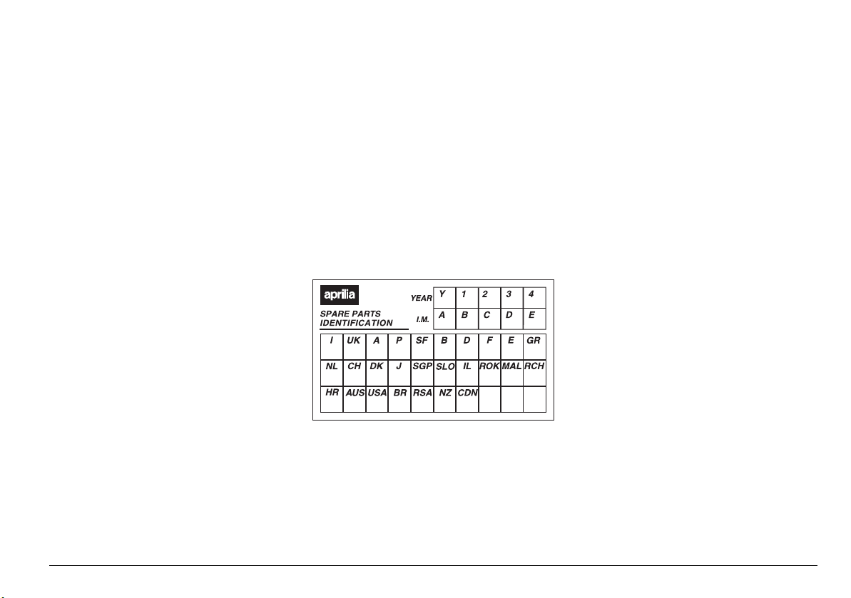
NOTE Soon after purchasing the vehicle,
write down the identification data indicated
on the SPARE PARTS IDENTIFICATION
LABEL in the table here below. This label is
positioned on the left side of the seat
support; to read it, it is necessary to remove
the seat, see page 27
(UNLOCKING/LOCKING THE SEAT).
These data indicate:
– YEAR = year of manufacture (Y, 1, 2, ...);
– I.M. = modification code (A, B, C, ...);
– COUNTRY CODES = homologation
country (I, UK, A, ...).
and are to be supplied to the aprilia
Authorised Dealer as reference data for
the purchase of spare parts or specific
accessories of the model you have acquired.
In this manual the various versions are
indicated by the following symbols:
J
optional
VERSION:
+
Italy
2
Singapore
4
United
Kingdom
P
Slovenia
>
Austria
F
Israel
M
Portugal
e
South Korea
(
Finland
-
Malaysia
$
Belgium
@
Chile
A
Germany
*
Croatia
C
France
#
Australia
'
Spain
R
United States of
America
)
Greece
g
Brazil
/
Holland
1
South Africa
6
Switzerland
K
New Zealand
&
Denmark
%
Canada
,
Japan

4
use and maintenance Pegaso 650 I.E. STRADA - TRAIL
TABLE OF CONTENTS
SAFETY WARNINGS................................................. 2
TECHNICAL INFORMATION..................................... 2
WARNINGS - PRECAUTIONS - GENERAL ADVICE 2
SAFE DRIVE BASIC SAFETY RULES ................. 6
CLOTHING ........................................................... 8
ACCESSORIES .................................................... 8
LOAD .................................................................... 9
ARRANGEMENT OF THE MAIN ELEMENTS ........ 10
ARRANGEMENT OF THE
INSTRUMENTS/CONTROLS................................... 14
INSTRUMENTS AND INDICATORS........................ 15
INSTRUMENTS AND INDICATORS
TABLE................................................................. 16
MULTIFUNCTION COMPUTER ......................... 18
MENU ................................................................. 19
SERVICE INTERVAL.......................................... 24
ALARM DISPLAY ............................................... 24
MAIN INDEPENDENT CONTROLS......................... 25
CONTROLS ON LEFT HANDLEBAR ................. 25
CONTROLS ON THE RIGHT PART OF
THE HANDLEBAR .............................................. 25
IGNITION SWITCH ............................................. 26
STEERING LOCK ............................................... 27
AUXILIARY EQUIPMENT ........................................ 27
UNLOCKING/LOCKING THE SEAT ................... 27
GLOVE COMPARTMENT .................................. 28
TOOL KIT COMPARTMENT .............................. 28
SPECIAL TOOLS
J........................................ 29
ACCESSORIES
J.......................................... 30
MAIN COMPONENTS .............................................. 31
FUEL................................................................... 31
BRAKE FLUID - recommendations..................... 33
DISC BRAKES .................................................... 34
FRONT BRAKE .................................................. 35
REAR BRAKE..................................................... 37
COOLANT........................................................... 38
TYRES ................................................................ 40
ENGINE OIL ....................................................... 41
CLUTCH ............................................................. 42
ADJUSTING THE REAR BRAKE
CONTROL LEVER CLEARANCE....................... 43
EXHAUST SILENCERS...................................... 43
EXHAUST SILENCERS...................................... 44
INSTRUCTIONS FOR USE...................................... 44
GETTING ON AND OFF THE VEHICLE ........... 44
PRELIMINARY CHECKING OPERATIONS ...... 46
PRELIMINARY CHECKING OPERATIONS ...... 47
STARTING ......................................................... 48
MOVING OFF AND RIDING .............................. 50
RUNNING-IN...................................................... 53
STOPPING......................................................... 54
PARKING ........................................................... 54
POSITIONING THE VEHICLE ON
THE STAND....................................................... 55
SUGGESTIONS TO PREVENT THEFT ............ 56
MAINTENANCE ...................................................... 57
REGULAR SERVICE INTERVALS CHART....... 58
IDENTIFICATION DATA .................................... 60
JOINTS WITH CLICK CLAMPS AND WITH SCREW
CLAMPS ............................................................ 60
CHECKING THE ENGINE OIL LEVEL AND
TOPPING UP ..................................................... 61
FRONT WHEEL ................................................. 62
REAR WHEEL ................................................... 64
POSITIONING THE VEHICLE ON
THE REAR SUPPORT STAND
J ................. 67
POSITIONING THE VEHICLE ON
THE FRONT SUPPORT STAND
J............... 67
DRIVE CHAIN .................................................... 68
REMOVING THE OIL SUMP GUARD ............... 70
REMOVING THE DRIVE CHAIN GUARDS....... 70
REAR SUSPENSION......................................... 70
CHECKING THE BRAKE PAD WEAR............... 72
IDLING ADJUSTMENT ...................................... 73
ADJUSTING THE ACCELERATOR
CONTROL.......................................................... 74
SPARK PLUG .................................................... 75
BATTERY........................................................... 77
CHECKING AND CLEANING THE TERMINALS 78
REMOVING THE BATTERY .............................. 79
CHARGING THE BATTERY .............................. 80
INSTALLING THE BATTERY ............................ 80
LONG INACTIVITY OF THE BATTERY ............ 81
CHECKING THE SWITCHES ............................ 81
CHANGING THE FUSES................................... 82
ADJUSTING THE VERTICAL
HEADLIGHT BEAM ........................................... 83
INSTRUMENT PANEL LIGHTING ..................... 83
BULBS ............................................................... 84
CHANGING THE HEADLIGHT BULBS ............. 84
CHANGING THE NUMBER PLATE BULB ........ 86
TRANSPORT........................................................... 86
CLEANING .............................................................. 86
LONG PERIODS OF INACTIVITY ..................... 88
TECHNICAL DATA ................................................. 90
LUBRICANT CHART.......................................... 93
WIRING DIAGRAM - Pegaso 650 I.E. ............... 94
WIRING DIAGRAM KEY - Pegaso 650 I.E. ....... 95
Authorised Dealers and Service Centres ........... 96
safe drive
6
use and maintenance Pegaso 650 I.E. STRADA - TRAIL
SAFE DRIVE BASIC SAFETY
RULES
To ride the vehicle it is necessary to be in
possession of all the requirements
prescribed by law (driving licence,
minimum age, psychophysical ability,
insurance, state taxes, vehicle registration,
number plate, etc.).
Gradually get to know the vehicle by
driving it first in areas with low traffic and/or
private areas.
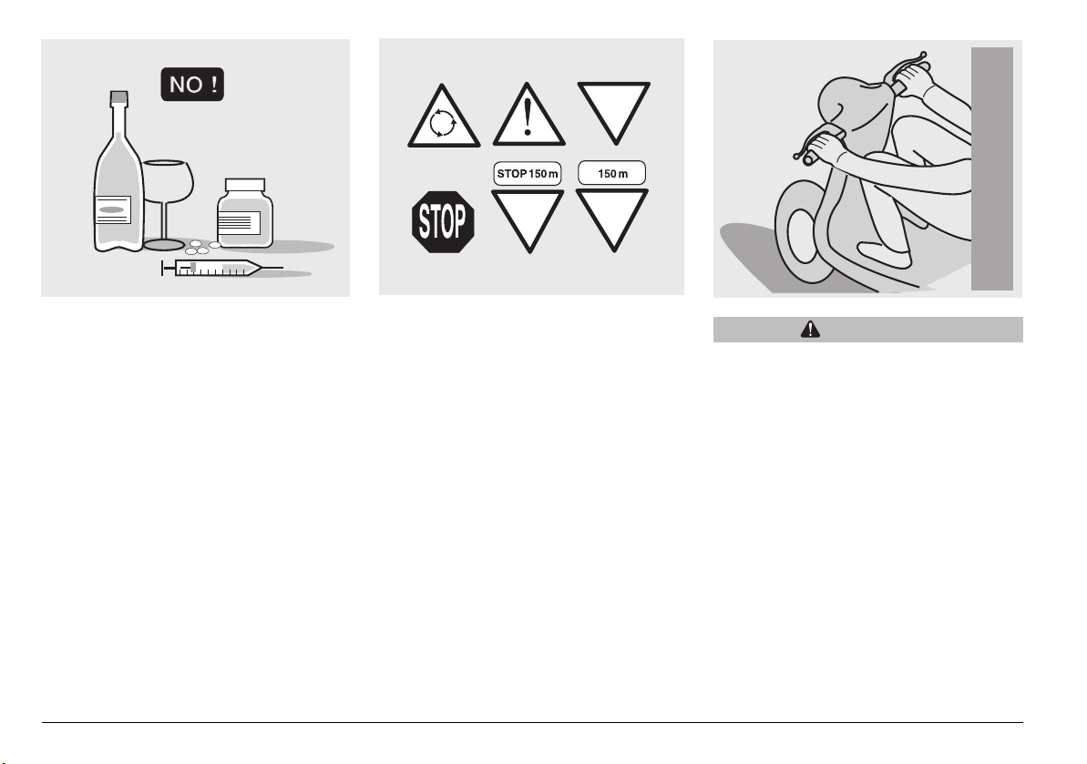
The use of medicines, alcohol and drugs or
psychotropic substances notably increases
the risk of accidents.
Be sure that you are in good
psychophysical conditions and fit for riding
and pay particular attention to physical
weariness and drowsiness.
Most road accidents are caused by the
rider’s lack of experience.
NEVER lend the vehicle to beginners and,
in any case, make sure that the rider has
all the requirements for driving.
Rigourously observe all road signs and
national and local road regulations.
Avoid abrupt movements that can be
dangerous for yourself and other people
(for example: wheeling, speeding, etc.);
and give due consideration to the road
surface, visibility and other driving
conditions.
Avoid obstacles that could damage the
vehicle or make you lose control.
Avoid riding in the slipstream created by
preceding vehicles in order to increase
your speed.
WARNING
Always ride with both hands on the
handlebars and both feet on the
footrests (or on the rider’s footboards),
in the correct driving posture.
Avoid standing up or stretching your
limbs while driving.
7
use and maintenance Pegaso 650 I.E. STRADA - TRAIL
The rider should pay attention and avoid
distractions caused by people, things and
movements (never smoke, eat, drink, read,
etc.) while driving.
Use only the vehicle’s specific fuels and
lubricants indicated in the “LUBRICANT
CHART”; check all oil, fuel and coolant
levels regularly.
If the vehicle has been involved in an
accident, make sure that no damage has
occurred to the control levers, pipes, wires,
braking system and vital parts.
If necessary, have the vehicle inspected by
an aprilia Authorised Dealer who should
carefully check the frame, handlebars,
suspensions, safety parts and all the
devices that you cannot check by yourself.
Always remember to report any
malfunction to the technicians to help them
in their work.
Never use the vehicle when the amount of
damage it has suffered endangers your
safety.
Never change the position, inclination or
colour of: number plate, direction
indicators, lights and horns.
Any modification of the vehicle will result in
the invalidity of the guarantee.
Any modification of the vehicle and/or the
removal of original components can
compromise vehicle performance levels
and safety or even make it illegal to ride.
We recommend respecting all regulations
and national and local provisions regarding
the equipment of the vehicle.
In particular, avoid all modifications that
increase the vehicle’s performance levels
or alter its original characteristics.
Never race with other vehicles.
ONLY ORIGINALS
8
use and maintenance Pegaso 650 I.E. STRADA - TRAIL
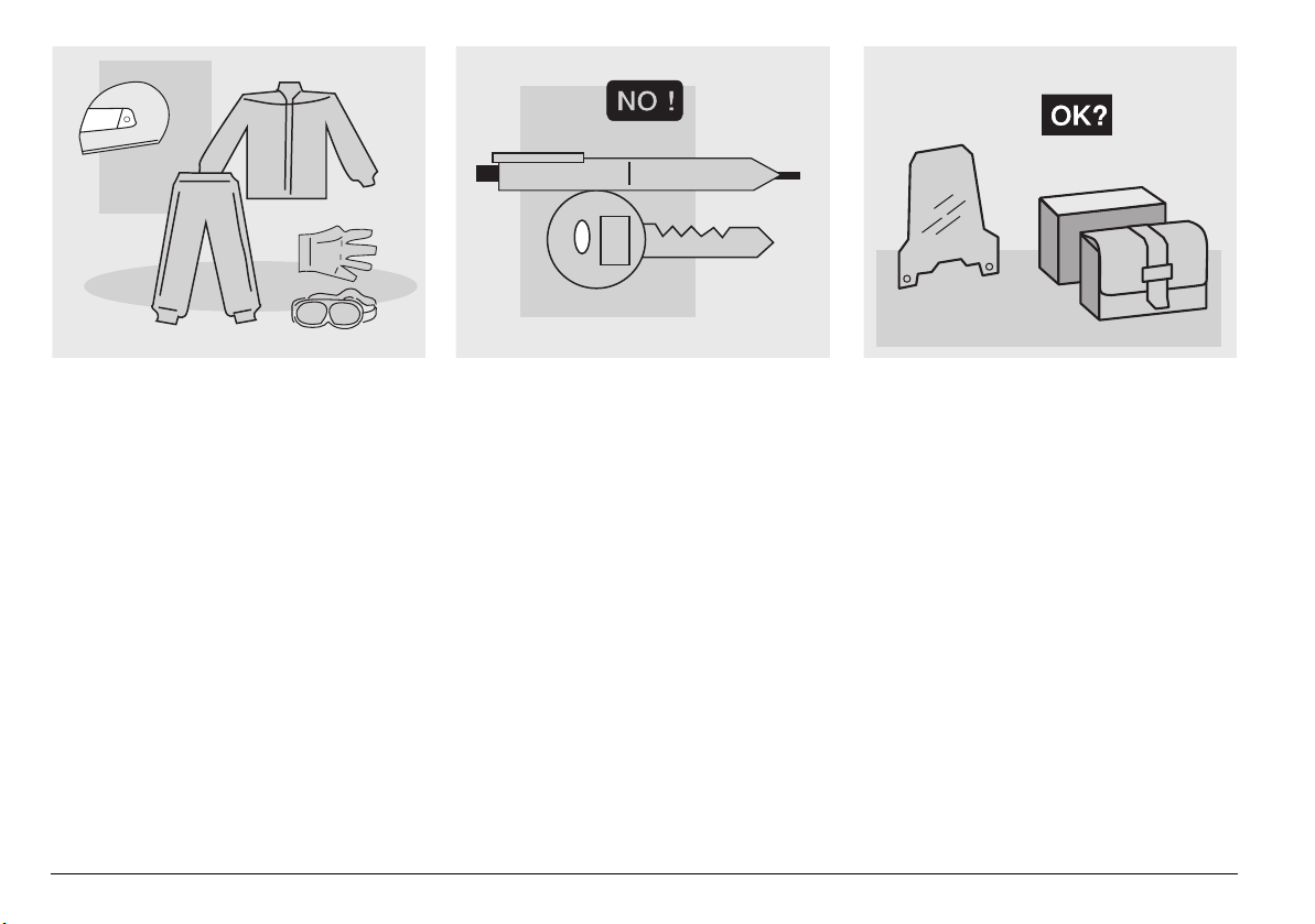
CLOTHING
Before starting, always wear a correctly
fastened crash helmet. Make sure that it is
homologated, in good condition, of the
right size and that the visor is clean.
Wear protective clothing, preferably in light
and/or reflecting colours. In this way you
will make yourself more visible to the other
riders, thus notably reducing the risk of
being knocked down, and you will be more
protected in case of fall.
This clothing should be very tight-fitting
and fastened at the wrists and ankles;
strings, belts and ties should not be
hanging loose; prevent these and other
objects from interfering with driving by
getting entangled with moving parts or
driving mechanisms.
Do not keep objects that can be dangerous
in case of fall, for example pointed objects
like keys, pens, glass vials etc. in your
pockets (the same recommendations also
apply to a possible passenger).
ACCESSORIES
The owner of the vehicle is responsible for
the choice, installation and use of any
accessory.
Avoid installing accessories that cover
horns or lights or that could impair their
functions, limit the suspension stroke and
the steering angle, hamper the operation of
the controls and reduce the ground
clearance and the angle of inclination in
turns.
Avoid using accessories that hamper
access to the controls, since this can
prolong reaction times during an
emergency.
Big fairings and windshields installed on
the vehicle may produce aerodynamic
forces that affect the stability of the vehicle,
especially when riding at high speed.
9
use and maintenance Pegaso 650 I.E. STRADA - TRAIL
Make sure that the equipment is well
fastened to the vehicle and not dangerous
during driving.
Do not install electrical devices and do not
modify those already existing to avoid
electrical overloads, because the vehicle
could suddenly stop or there could be a
dangerous current shortage in the horn
and in the lights.
aprilia recommends the use of genuine
accessories (aprilia genuine accessories).
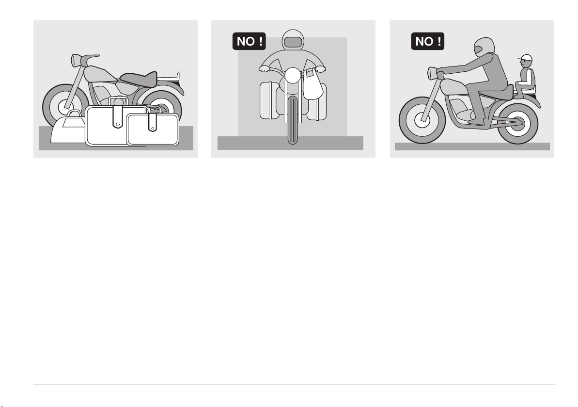
LOAD
Be careful and moderate when loading
your luggage. Keep any luggage loaded as
close as possible to the centre of gravity of
the vehicle and evenly distribute the load
on both sides, in order to reduce
unbalance to the minimum. Furthermore,
make sure that the load is firmly secured to
the vehicle, especially during long trips.
Avoid hanging bulky, heavy and/or
dangerous objects on the handlebars,
mudguards and forks, because the vehicle
might respond more slowly in turns and its
manoeuvrability could be unavoidably
impaired.
Do not place bags that are too bulky on the
vehicle sides and do not ride with the crash
helmet hanging on one side, because they
could hit people or obstacles, making you
lose control of the vehicle.
Do not carry any bag if it is not tightly
secured to the vehicle.
Do not carry bags which protrude too much
from the luggage-rack or which cover the
lights, horn or indicators.
Do not carry animals or children on the
glove compartment or on the luggage rack.
Do not exceed the maximum load allowed
for each bag.
When the vehicle is overloaded, its stability
and its manoeuvrability can be
compromised.
10
use and maintenance Pegaso 650 I.E. STRADA - TRAIL
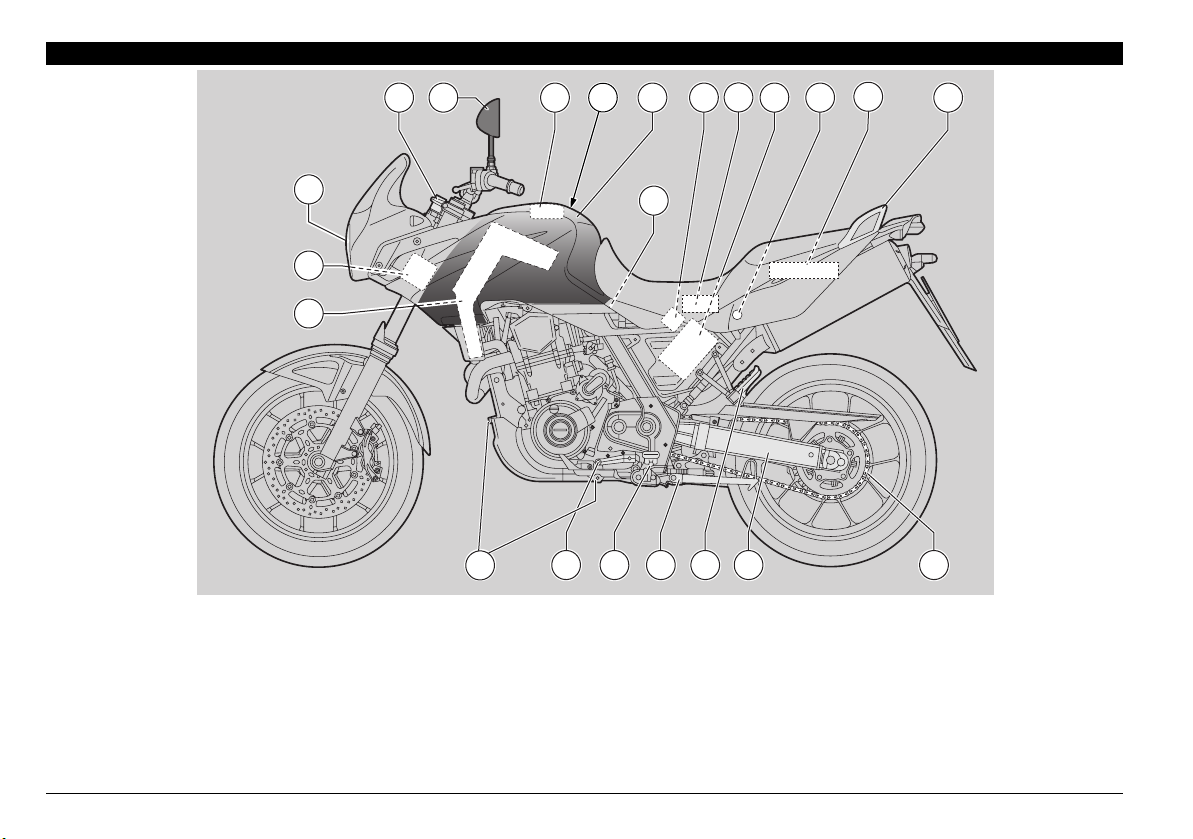
1
2 3 10 5 8 16 9
7
18
4
15 14 13 12 11 17
6
19
20
22
21
STRADA
ARRANGEMENT OF THE MAIN ELEMENTS
KEY
1) Headlight
2) Ignition switch/steering lock
3) Left rear-view mirror
4) Fuel tank filler cap
5) Fuel tank
6) Battery
7) Electronic control unit
8) Fuse carrier
9) Passenger grab rail
10) Glove compartment
11) Swinging arm
12) Passenger left footrest
(snapping, closed/open)
13) Side stand
14) Rider left footrest
15) Gear shift lever
16) Seat lock
17) Drive chain
18) Engine oil tank
19) Tool kit
20) Idle speed adjuster
21) Oil drain plugs
22) Underseat compartment
11
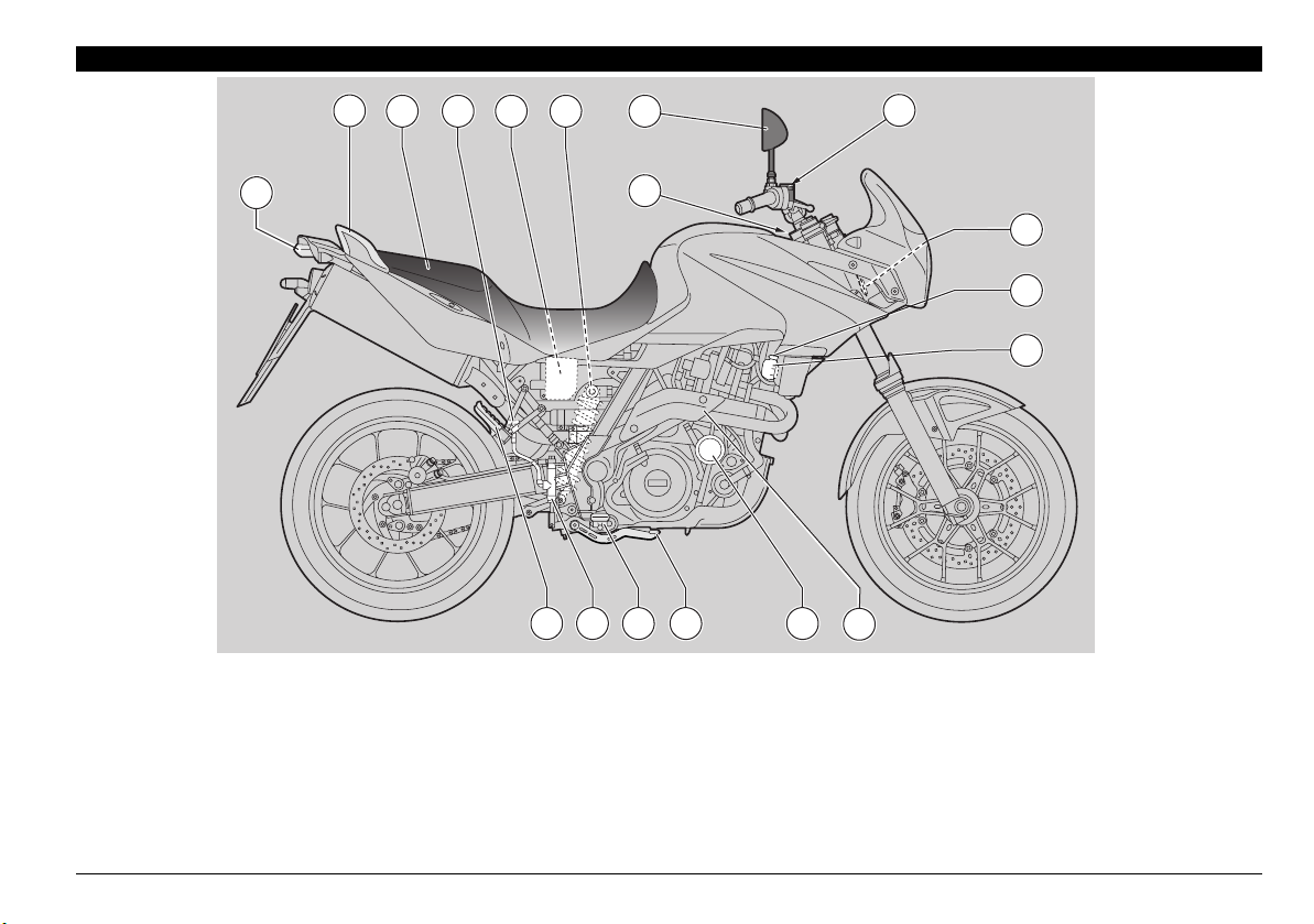
use and maintenance Pegaso 650 I.E. STRADA - TRAIL
KEY
1) Tail light
2) Passenger grab rail
3) Seat
4) Rear brake fluid tank
5) Air filter
6) Rear shock absorber
7) Engine oil level plug-dipstick
8) Front brake fluid tank
9) Right rear-view mirror
10) Horn
11) Engine oil filter
12) Rear brake control lever
13) Rider right footrest
14) Rear brake master cylinder
15) Passenger right footrest
(snapping, closed/open)
16) Coolant expansion tank
cap
17) Coolant expansion tank
18) CO sensor plug
1
3 5
17
16
10
6 94
15 14
2
7
8
1213 11
18
12
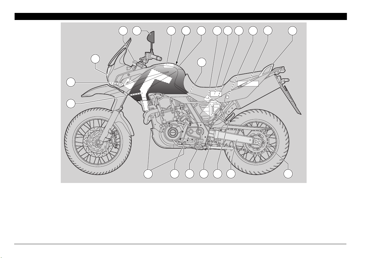
use and maintenance Pegaso 650 I.E. STRADA - TRAIL
KEY
1) Headlight
2) Ignition switch/steering lock
3) Left rear-view mirror
4) Fuel tank filler cap
5) Fuel tank
6) Battery
7) Electronic control unit
8) Fuse carrier
9) Passenger grab rail
10) Glove compartment
11) Swinging arm
12) Passenger left footrest
(snapping, closed/open)
13) Side stand
14) Rider left footrest
15) Gear shift lever
16) Seat lock
17) Drive chain
18) Engine oil tank
19) Tool kit
20) Idle speed adjuster
21) Oil drain plugs
22) Underseat compartment
1
2 3 10 5 8 16 9
7
18
4
15 14 13 12 11 17
6
19
20
22
21
TRAIL
13
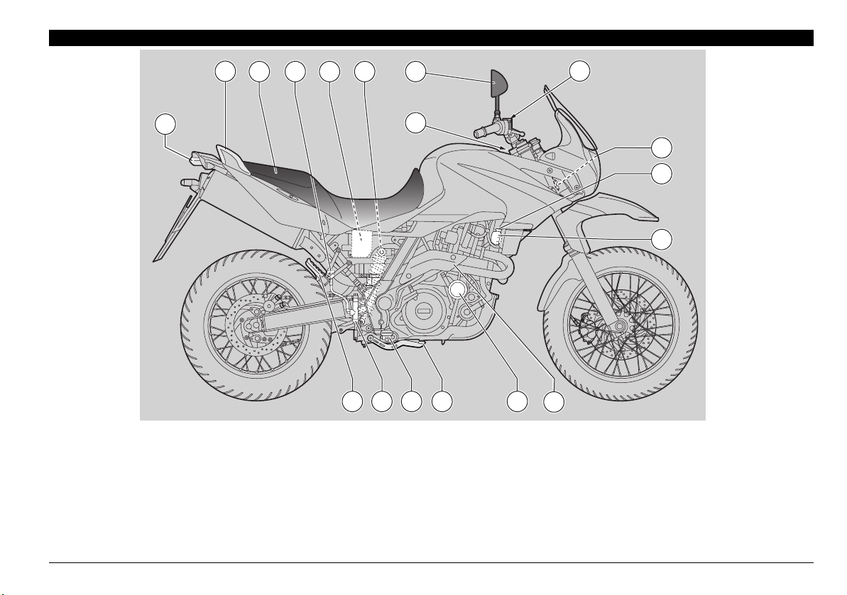
use and maintenance Pegaso 650 I.E. STRADA - TRAIL
KEY
1) Tail light
2) Passenger grab rail
3) Seat
4) Rear brake fluid tank
5) Air filter
6) Rear shock absorber
7) Engine oil level plug-dipstick
8) Front brake fluid tank
9) Right rear-view mirror
10) Horn
11) Engine oil filter
12) Rear brake control lever
13) Rider right footrest
14) Rear brake master cylinder
15) Passenger right footrest
(snapping, closed/open)
16) Coolant expansion tank
cap
17) Coolant expansion tank
18) CO sensor plug
1
3 5
17
16
10
6 94
15 14
2
7
8
1213 11
18
14
use and maintenance Pegaso 650 I.E. STRADA - TRAIL
6
7
812
1 4 5
11 10
9
2
3
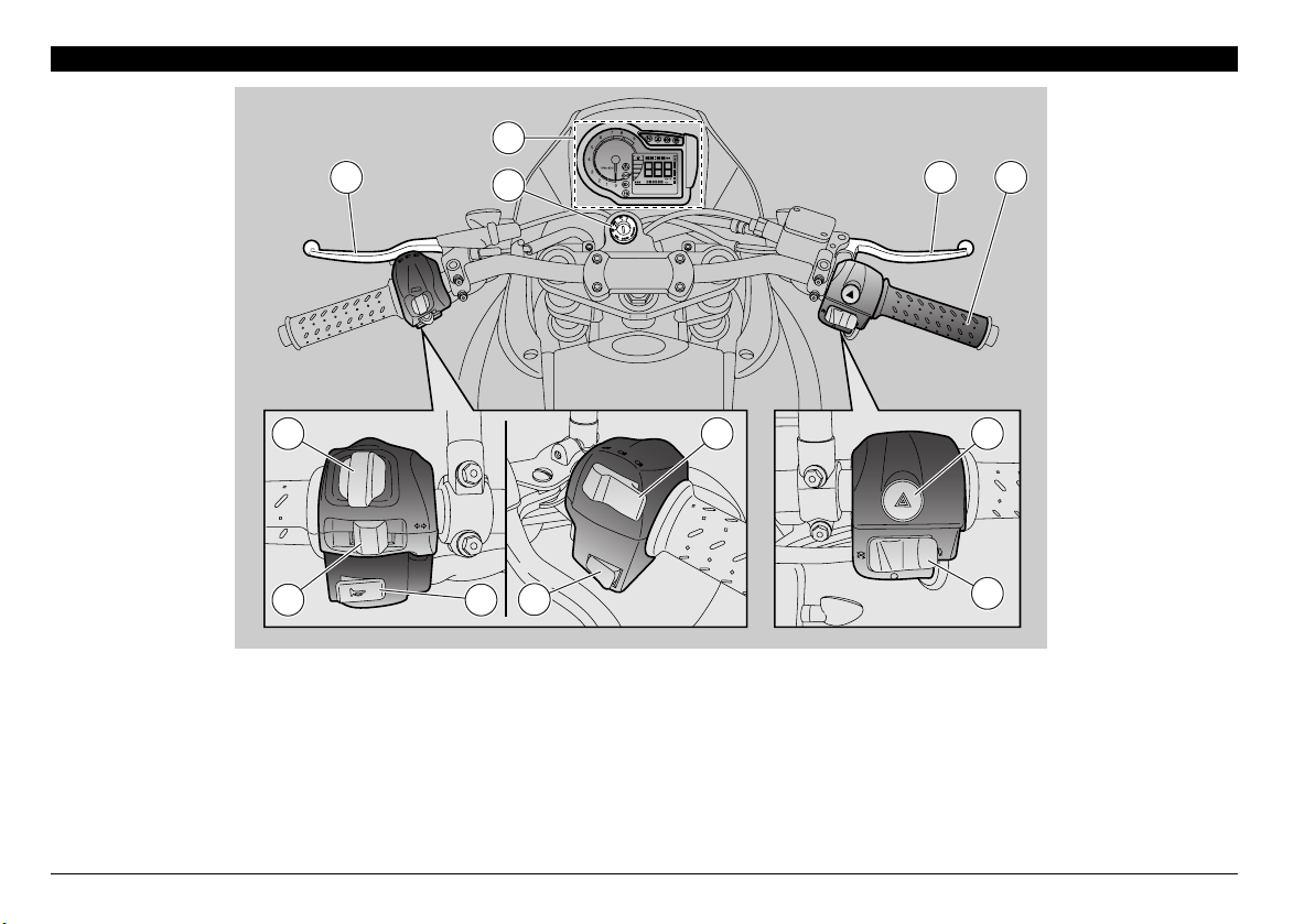
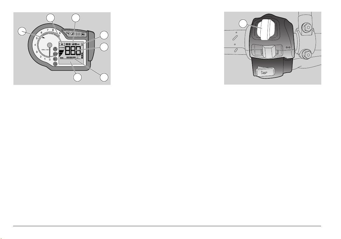
ARRANGEMENT OF THE INSTRUMENTS/CONTROLS
KEY
1) Clutch lever
2) Instruments and indicators
3) Ignition switch/steering lock (--)
4) Front brake lever
5) Throttle grip
6) Emergency flasher button ()
7) Engine start-stop switch (--)
8) Dimmer switch (-)
9) Fuel filler cap cover release switch
10) Horn push button ()
11) Direction indicator switch ()
12) MODE switch
15
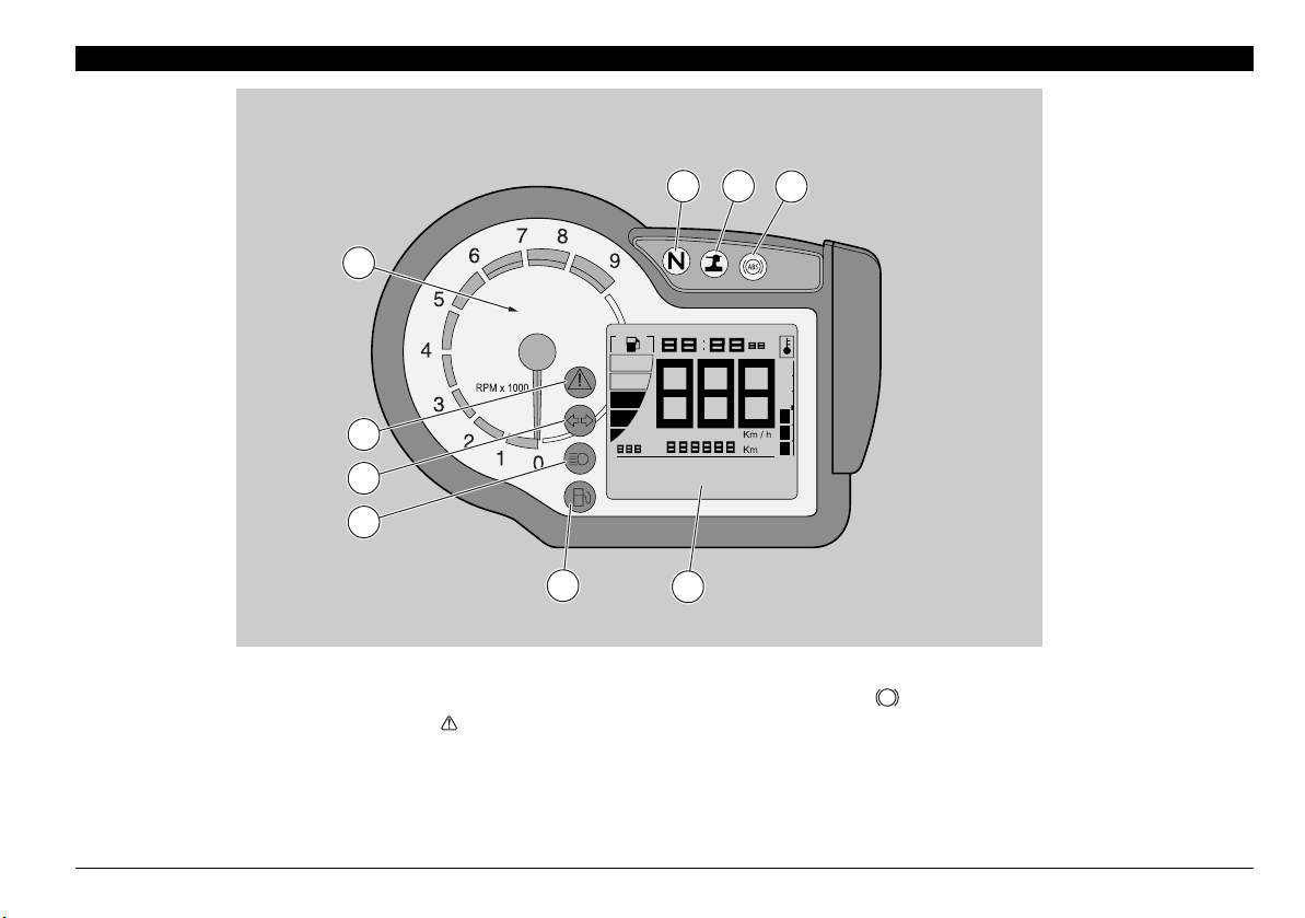
use and maintenance Pegaso 650 I.E. STRADA - TRAIL
6
7
9
5
4
3
2
8
1
KEY
1) Revolution counter
2) Red alarm light: vehicle maintenance ( )
3) Green direction indicator warning light ()
4) Blue high beam warning light ()
5) Orange low fuel warning light ()
6) Green neutral indicator warning light ()
7) Yellow side stand light (
h
)
8) Orange ABS light ( ) (only for vehicles equipped with ABS)
9) Multifunction digital display.
ABS
INSTRUMENTS AND INDICATORS
16
use and maintenance Pegaso 650 I.E. STRADA - TRAIL
INSTRUMENTS AND INDICATORS TABLE
When the ignition key is turned to “” with the engine stopped, all warning lights, except “Heated handgrips” light, come on for a LED
check-up and go out after three seconds. If one or more warning lights do not come on at this stage, contact a aprilia Authorised
Dealer.
Description Function
Multifunction
digital display
Speedometer (km/h - MPH)
Displays current, average or maximum riding speed (in kilometres or miles) depending on presetting,
see page 18 (MULTIFUNCTION COMPUTER).
Odometer (KM - Mi) Displays partial or total Km/miles run, see page 18 (MULTIFUNCTION COMPUTER).
Coolant temperature
(°C/°F)
Displays engine coolant temperature, see page 18 (MULTIFUNCTION COMPUTER).
Do not leave the ignition switch on “”, since the cooling fans would
stop regardless of the coolant temperature and in this case the
temperature would increase even further.
If the pointer gets near the danger area, stop the engine, turn the key to “” and wait until the
cooling fan is disconnected.
Now turn the key to “” and check coolant level, see page 38 (COOLANT).
Contact an
aprilia Authorised Dealer.
If the maximum allowed temperature is exceeded (118 °C - 244
°F), the engine may be seriously damaged.
Fuel level
(STRADA version only)
Displays fuel quantity in the tank, see page 18 (MULTIFUNCTION COMPUTER).
Clock Displays time (hour and minutes) as preset, see page 18 (MULTIFUNCTION COMPUTER).
Battery voltage V
BATT
Displays the battery voltage in Volts, see page 18 (MULTIFUNCTION COMPUTER).
Lap timer Displays the different lap times, as preset, see page 18 (MULTIFUNCTION COMPUTER).
Diagnosis
In case a serious failure is detected, one that might jeopardise the vehicle or the rider's safety,
the panel will show an icon indicating the failure cause (such as: oil pressure
, maintenance
intervals ).
If the wording " SERVICE" appears during normal engine
operation, it means that the ECU or the instrument panel have
detected a failure. In many cases the engine keeps running with limited performance;
contact an
aprilia Authorised Dealer immediately.
Revolution counter rpm
Indicates the number of revolutions of the engine per minute.
Never exceed the engine max. speed rate, see page 53 (RUNNING-IN).
CAUTION
CAUTION
CAUTION
CAUTION
17
use and maintenance Pegaso 650 I.E. STRADA - TRAIL
Error warning light
It comes on to signal a fault in case of: oil pressure alarm, overtemperature alarm, problems with the
injection system or when maximum rpm are exceeded.
It flashes when engine is off to indicate that the antitheft system is active.
It comes on flashing if the maximum rpm are exceeded.
If the light remains on after the engine start or comes on during
the normal operation of the engine, together with one of the two
symbols on the display: “
efi”, “”, this means that a fault of the injection system was
detected (
efi), or low engine oil pressure () was detected. In this case, stop the engine
immediately and contact an aprilia Authorised Dealer.
Direction indicator warning light Blinks when the direction indicators are on.
High beam warning light Comes on when the high beam bulbs are on or when the headlight signaller is operated.
Low fuel warning light
It comes on when the quantity of fuel left in the tank is approx. 3
b.
In this case, top up as soon as possible, see page 31 (FUEL).
Refuel with ignition key in stop position in order to get a correct indication of the light.
Neutral indicator warning light Comes on when the gear is in neutral.
Side stand down light
h
Turns on when the side stand is down.
ABS light (if ABS is fitted) (only for
vehicles equipped with ABS)
It comes on in case of ABS failure.
Description Function
CAUTION
ABS
18
use and maintenance Pegaso 650 I.E. STRADA - TRAIL
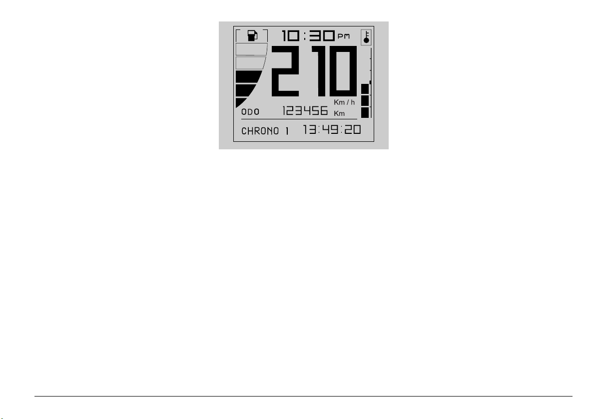
MULTIFUNCTION COMPUTER
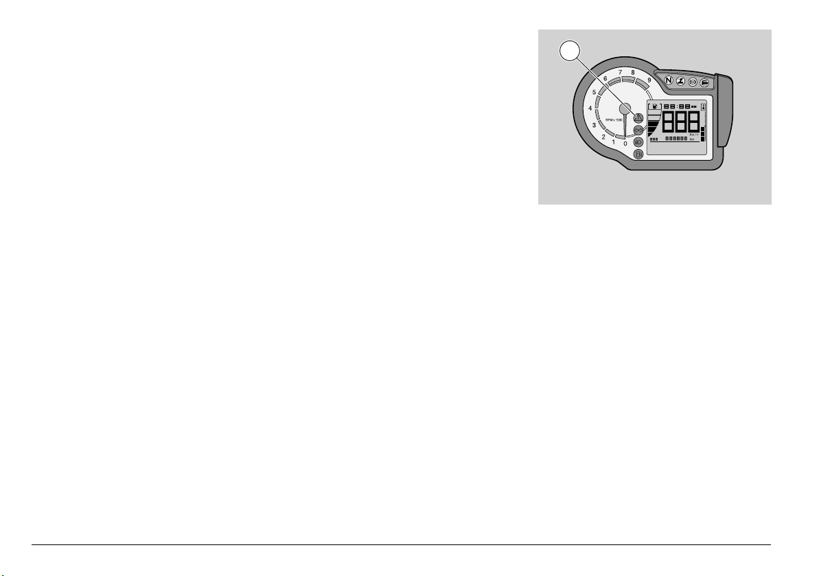
When you turn the ignition key to "", the
following instrument panel lights will turn
on for 2 seconds:
- The "PEGASO 650 STRADA-TRAIL"
logo
- All lights, except “Heated handgrips light”
- Backlighting
Rev counter index (1) moves to maximum
value, as set by the user.
During the initial check-up, all instruments
will briefly show the current values of the
corresponding parameters.
The display shows the following standard
settings:
A) coolant temperature;
B) fuel quantity (STRADA version only);
C) clock;
D) speedometer;
E) odometer;
F) on-board computer and accessories
functions.
MODE selector (2) features three
positions: a left one to decrease values
and scroll the drop-down menus, a right
one to increase values and scroll the drop-
down menus in the other direction, and a
centre one to confirm values by pressing
the button.
2
B C
F
A
D
E
1
19
use and maintenance Pegaso 650 I.E. STRADA - TRAIL
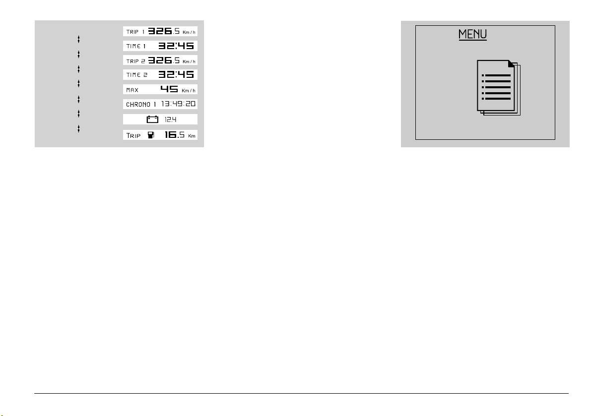
Turn selector (2) to display on the LCD the
pages indicating in zone (F) the following
quantities:
A) TRIP METER 1
B) TRIP TIME 1
C) TRIP METER 2
D) TRIP TIME 2
E) MAXIMUM SPEED
F) LAP TIMER
G) BATTERY VOLTAGE
H) KM COVERED W/FUEL RESERVE
(distance covered on fuel reserve for trips
longer than 2 km).
Trip meter 1 and 2 can be reset: press
selector (2) for a certain time in the centre
position to reset all quantities concerning
the active trip meter.
After the distance covered on fuel reserve
(KM COVERED W/FUEL RESERVE), the
display shows the MENU page, but only if
vehicle is not moving.
MENU
If vehicle is stopped, it is possible to gain
access to the configuration menu from the
MENU page by pressing the MODE
selector in the centre position; while if
vehicle is moving, go back to the TRIP
METER 1 page.
Configuration menu options are:
EXIT
SETTINGS
LAP TIMER
DIAGNOSTICS
LANGUAGE
TRIP METER 1
TRIP TIME 1
TRIP METER 2
TRIP TIME 2
MAXIMUM SPEED
LAP TIMER
BATTERY VOL TAGE
KM COVERED W/FUEL RESERVE
20
use and maintenance Pegaso 650 I.E. STRADA - TRAIL
Settings
When the SETTINGS function is selected
the following options are displayed:
EXIT
TIME SETTINGS
GEAR SHIFT INDICATOR
BACK LIGHTING
CHANGE THE CODE
CODE RECOVERY
UNLOCK SAFETY LOCKS
Once the operation is over, the instrument
panel goes back to main menu.
TIME SETTINGS
This mode allows you to set the clock. The
main page with "CLOCK SETTING" is
displayed.
As soon as you enter this mode, indication
of minutes disappears and only hours are
displayed. Hour value is increased every
time the MODE selector is pressed to the
right, once the value reaches 12 it goes
back to 0. In the same way, hour value
decreases every time the MODE selector
is pressed to the left, once the value
reaches zero, it goes to 12 when the
MODE selector is again pressed to the
left..
A Confirmation signal stores the set value
and lets you go on to minutes setting.
As soon as you enter this mode, indication
of hours disappears and only minutes are
displayed. Minute value increases every
time the MODE selector is pressed to the
right, once the value reaches 59, it goes
back when the MODE selector is again
pressed to the right.In the same way, value
decreases every time the MODE selector
is pressed to the left, once the value
reaches zero, it goes to 59 when the
MODE selector is again pressed to the left.
A Confirmation signal stores the set value
and lets you quit clock setting mode.
GEAR SHIFT THRESHOLD
This function allows you to set the value for
the Gear shift indicator threshold. The
main page with "GEAR SHIFT
THRESHOLD" message is displayed.
Threshold value is increased by 100 RPM
every time the MODE selector is pressed
to the right, vice versa, threshold value is
decreased by 100 RPM every time the
MODE selector is pressed to the left.
If the upper or lower limit is reached and
you further press the selector, nothing will
happen.
Press the MODE selector to the centre
position to end the operation and store the
set value, the index goes back to zero and
the instrument panel goes back to
configuration menu page.
3
21
use and maintenance Pegaso 650 I.E. STRADA - TRAIL
When battery is connected for the first
time, the instrument panel sets to running-
in rpm value, the next time battery is
connected it sets to last set value.
RUNNING-IN RPM: 5000
MINIMUM RPM: 4000
MAXIMUM RPM: 8000
When the set threshold is exceeded, the
alarm light (3) on the instrument panel
flashes until the value goes below the
threshold.
BACK LIGHTING
This function allows you to set
backlighting: three levels are available.
Every time the MODE selector is pressed
to the right or to the left, the following icons
are displayed:
LOW
MEAN
HIGH
Press the MODE selector to the centre
position to set the instrument panel back to
SETTINGS MENU.
CHANGE THE CODE
This function is used when the old code is
available and is to be changed.
Within this function, the following message
is displayed:
"INSERT THE OLD CODE"
As soon as the old code is acknowledged,
the new code is requested; the following
message is displayed:
"INSERT THE NEW CODE"
Once the operation is over, the display
goes back to DIAGNOSIS menu. If you
entered with the code, this operation will
not be allowed.
Once the operation is over, the instrument
panel goes back to SETTINGS menu.
22
use and maintenance Pegaso 650 I.E. STRADA - TRAIL
CODE RECOVERY
This function is used when the old code is
not available and you need to change it. In
this case it is necessary to insert at least
two keys in the ignition switch. The first key
is already inserted, a second key is
requested with the message:
"INSERT THE 2nd KEY"
The instrument panel remains on in-
between these two keys; if the second key
is not inserted within 20 seconds the
operation is aborted. When the second key
is acknowledged, the new code is
requested with the message:
"INSERT THE NEW CODE"
Once the operation is over, the display
goes back to DIAGNOSIS menu. If you
entered with the code, this operation will
not be allowed.
Once the operation is over, the instrument
panel goes back to SETTINGS menu.
UNLOCK SAFETY LOCKS
In case of failure to the stand sensor, the
neutral and clutch switch, use function
"UNLOCK SAFETY LOCKS" to disable the
safety logic to be able to start the engine.
The display will show "SERVICE".
The safety logic is re-enabled when turning
the key off.
WARNING
This function should be used only in an
emergency.
Lap timer
When the LAP TIMER function is selected
the following options are displayed:
EXIT
VIEW TIMES
DELETE TIMES
VIEW TIMES
This function also displays the acquired lap
times. Briefly press the MODE selector to
the right and to the left to scroll the time
pages, press it for a certain time to set the
display back to the LAP TIMER menu. If
the battery is disconnected, stored times
are lost.
23
use and maintenance Pegaso 650 I.E. STRADA - TRAIL
DELETE TIMES
This function deletes the acquired lap
times. Deletion should be confirmed. Once
the operation is over, the display goes
back to LAP TIMER menu.
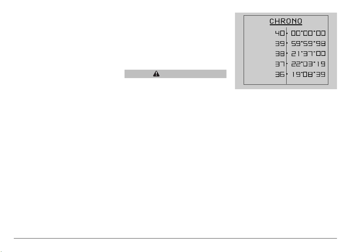
Lap time operation
To use the lap timer, set the display to the
main page indicating CHRONO, and then
wait to start the lap timer.
Briefly press the MODE selector to the
centre position, the lap timer starts
recording. Press again the MODE selector
to the centre position before 10 seconds
have elapsed from timer start, time
measurement is cancelled and a new one
is started. Press again the MODE selector
to the centre position after 10 seconds
have elapsed from timer start, time
measurement is interrupted and a new one
is started. Press the MODE selector for a
certain time to the centre position to
interrupt lap time set.
Once 40 lap times have been recorded,
acquisition ends and "FULL" is displayed:
stop the vehicle to read recorded lap times,
see page 54 (STOPPING), enter VIEW
TIMES option in the LAP TIMER menu.
A new timer session can be started only if
all previously recorded lap times are
deleted: enter the DELETE TIMES function
in the LAP TIMER menu.
Diagnosis
This menu interfaces with the systems
fitted to the motorcycle to carry out
diagnosis. To enable the menu, a
password is needed that is available only
to aprilia service centres.
Language
This menu allows you to choose the user's
interface language.
ITALIANO
ENGLISH
FRANCAIS
DEUTSCH
ESPAGNOL
24
use and maintenance Pegaso 650 I.E. STRADA - TRAIL
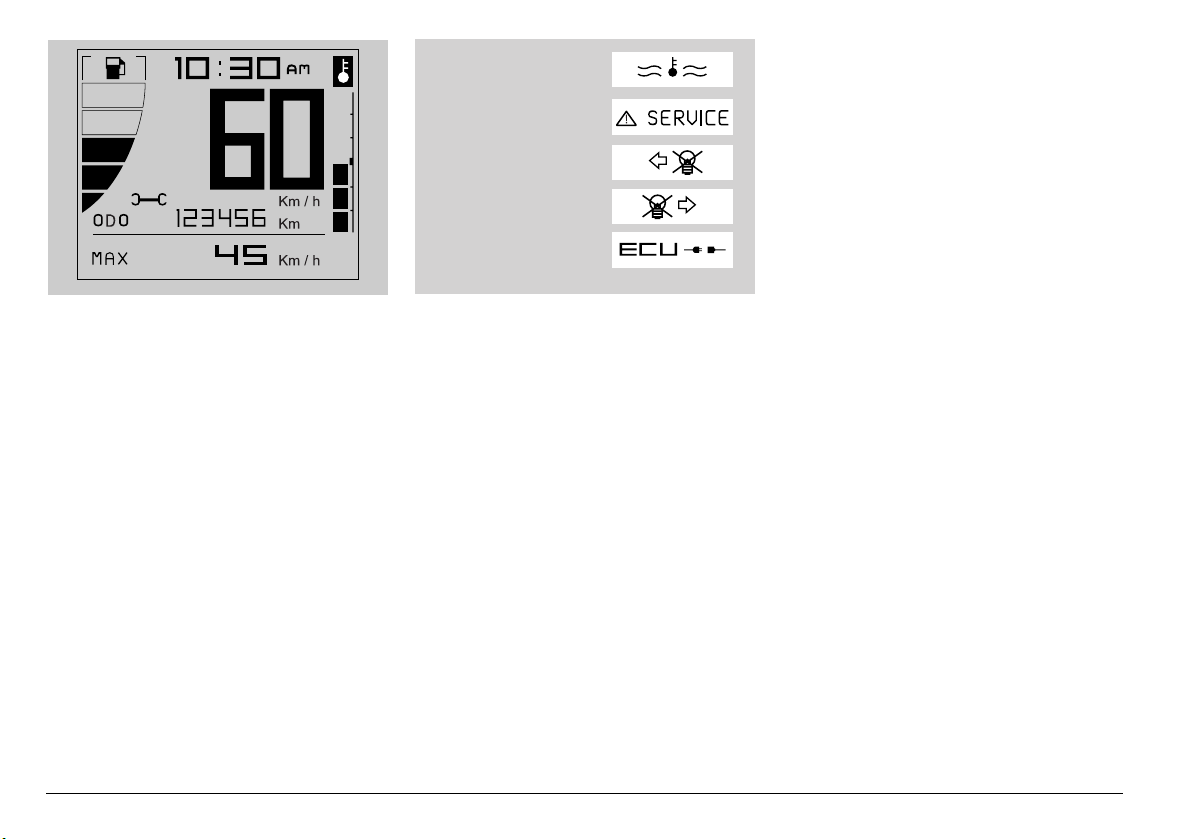
SERVICE INTERVAL
When the scheduled service intervals are
reached, an icon is displayed (symbol of a
spanner).
ALARM DISPLAY
In case a serious failure is detected, one
that might jeopardise the vehicle or the
rider's safety, the display will show an icon
indicating the failure cause, in the area
where the odometer usually is.
Alarms are divided in two groups
depending on their priority:
u High priority: overtemperature, ECU
errors, Instrument panel errors;
u Low priority: Direction indicators.
Direction indicators fault is indicated only
when all indicator leds are faulty.
Should there be many alarms with same
priority level, the relevant icons are
displayed alternatively.
High priority alarms do not allow you to
display low priority ones.
If the alarm light and the SERVICE icon
briefly come on it does not mean that there
is a failure.
ECU DISCONNECTED
RIGHT DIRECTION
INDICATOR FAULT
LEFT DIRECTION
INDICATOR FAULT
ECU ERRORS, INSTRUMENT
PANEL ERRORS
OVERTEMPERATURE
25
use and maintenance Pegaso 650 I.E. STRADA - TRAIL
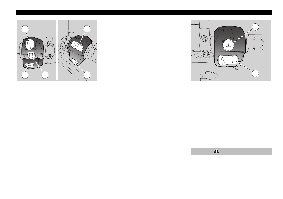
MAIN INDEPENDENT CONTROLS
CONTROLS ON LEFT HANDLEBAR
NOTE The electrical parts work only
when the ignition switch is in position “”.
1) HORN BUTTON ()
The horn is activated when the push
button is pressed.
2) DIRECTION INDICATOR SWITCH
()
Move the switch to the left to indicate the
turn to the left; move the switch to the right
to indicate the turn to the right.
Press the switch to turn off the direction
indicator.
3) MODE BUTTON
Move the MODE joystick to the left/right
or press it to scroll UP/DOWN and
select the multifunction display pages.
4) DIMMER SWITCH ( - )
When it is in position "" the parking
lights, the instrument panel light and the
low beam are always on.
When it is in left position "", the high
beam comes on.
When it is in right position "", the
passing is activated, to be used in case
of danger or emergency.
5) FUEL TANK CAP COVER RELEASE
BUTTON
Press it to open the cover on fuel tank
to gain access to the fuel filler.
CONTROLS ON THE RIGHT PART
OF THE HANDLEBAR
NOTE The electrical parts work only
when the ignition switch is in position “”.
6) ENGINE START / STOP SWITCH
( - -)
Set the switch to and press it in
position to start the engine: the
starter motor cranks the engine. For the
starting procedure, see page 48
(STARTING).
When set to the engine stops.
WARNING
Do not set the switch to while riding.
6
7
2 4
1 3 5
26
use and maintenance Pegaso 650 I.E. STRADA - TRAIL
1
CAUTION
With the engine stopped and the switch
in position "", the battery may run flat.
When the vehicle has come to rest, after
stopping the engine, leave the switch to
position .
7) EMERGENCY FLASHER BUTTON
()
Press the button to activate all direction
indicators.
Can be enabled or disabled only with
ignition switch to "". When activated,
the direction indicators stay active even
when removing the key. To disable it,
set ignition switch back to "".
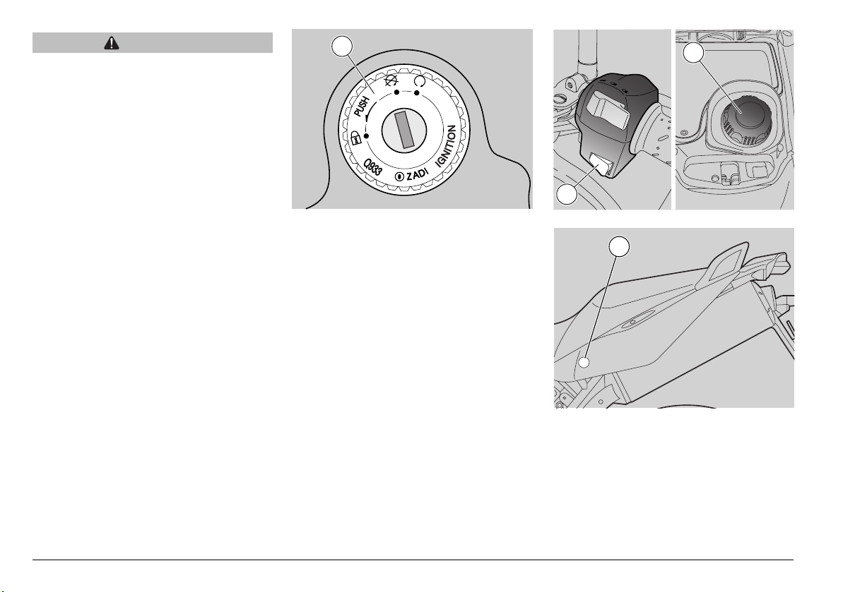
IGNITION SWITCH
The ignition switch (1) is positioned on the
upper plate of the steering column.
NOTE The key operates the ignition
switch/steering lock, the fuel filler cap
cover (3) release button (2) and the seat
lock (4).
Two keys are supplied together with the
vehicle (one spare key).
NOTE Do not keep the spare key on the
vehicle.
3
2
4
27
use and maintenance Pegaso 650 I.E. STRADA - TRAIL
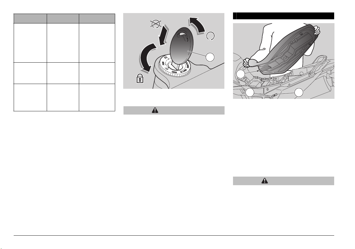
STEERING LOCK
WARNING
Never turn the key to position “” in
running conditions, in order to avoid
losing control of the vehicle.
OPERATION
To lock the steering:
u Completely turn the handlebar to the
right or to the left.
u Turn the key (1) to position “”.
u Press the key (1) and rotate it to position
“”.
u Withdraw the key (1).
AUXILIARY EQUIPMENT
UNLOCKING/LOCKING THE SEAT
u Position the vehicle on the stand, see
page 55 (POSITIONING THE VEHICLE
ON THE STAND).
u Insert the key (1) in the seat lock (2).
u Turn the key (1) clockwise and raise and
remove the seat.
To lock the seat:
u Position the flaps (3) in the seat, lower
and press the seat, making the lock
snap.
WARNING
Before leaving, make sure that the seat
is properly locked.
Position Function Key removal
Steering
lock
The steering
is locked. It
is not
possible to
start the
engine.
It is possible
to remove the
key.
The engine
cannot be
started.
It is possible
to remove the
key.
The engine
can be
started.
It is not
possible to
remove the
key.
1
2
1
3
28
use and maintenance Pegaso 650 I.E. STRADA - TRAIL
3
4
5
6
7
8
GLOVE COMPARTMENT
To gain access to the glove
compartment (2):
u Set the ignition switch to "" and press
the fuel filler cap cover release button
(1).
u Move the red safety hook to the left to
release it.
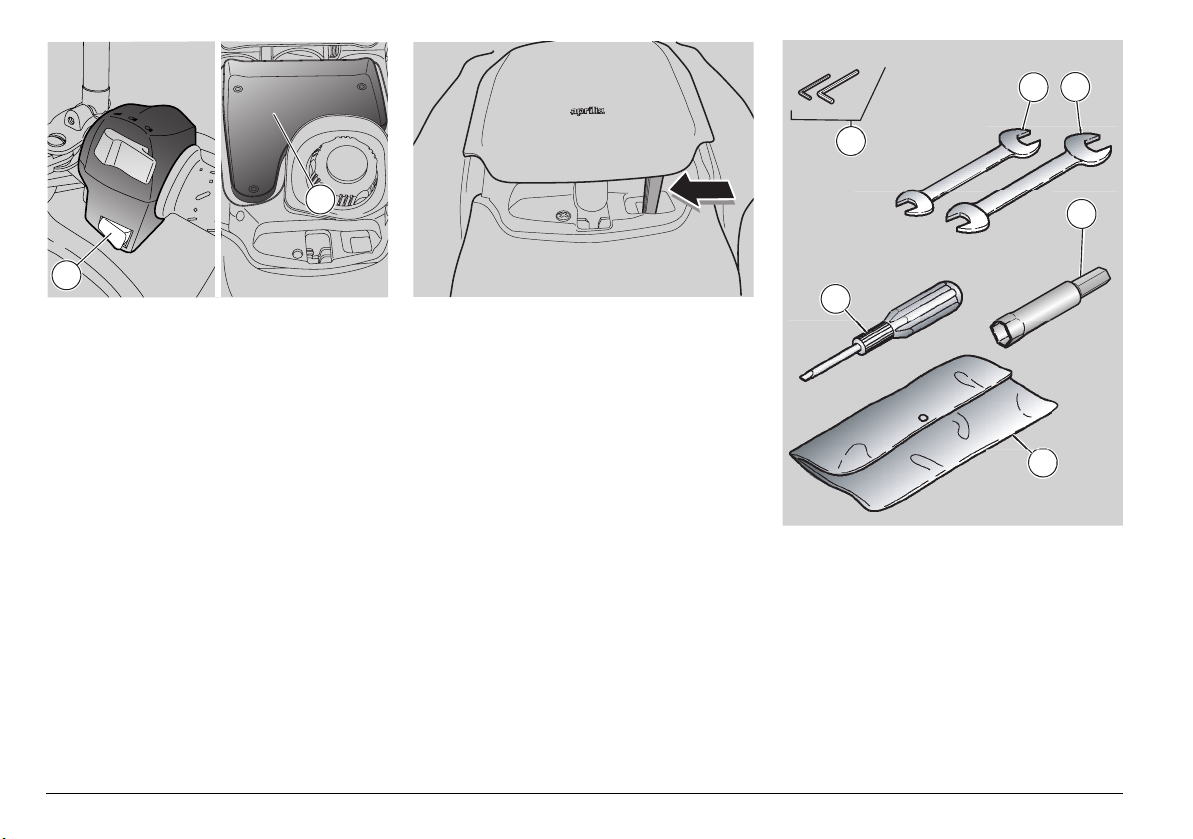
TOOL KIT COMPARTMENT
To gain access to the tool kit
compartment:
u Remove the seat, see page 27
(UNLOCKING/LOCKING THE SEAT)
The tool kit includes:
– 3, 4 mm bent hexagon spanners (3);
– 8 – 10 mm double fork spanner (4);
– 11 – 13 mm double fork spanner (5);
– 16 mm socket spanner for spark plug (6);
– double-ended, cross-/cut-headed
screwdriver (7);
– tool case (8);
– 13 mm combined wrench.
Maximum allowed weight: 1.5 kg.
2
1
29
use and maintenance Pegaso 650 I.E. STRADA - TRAIL
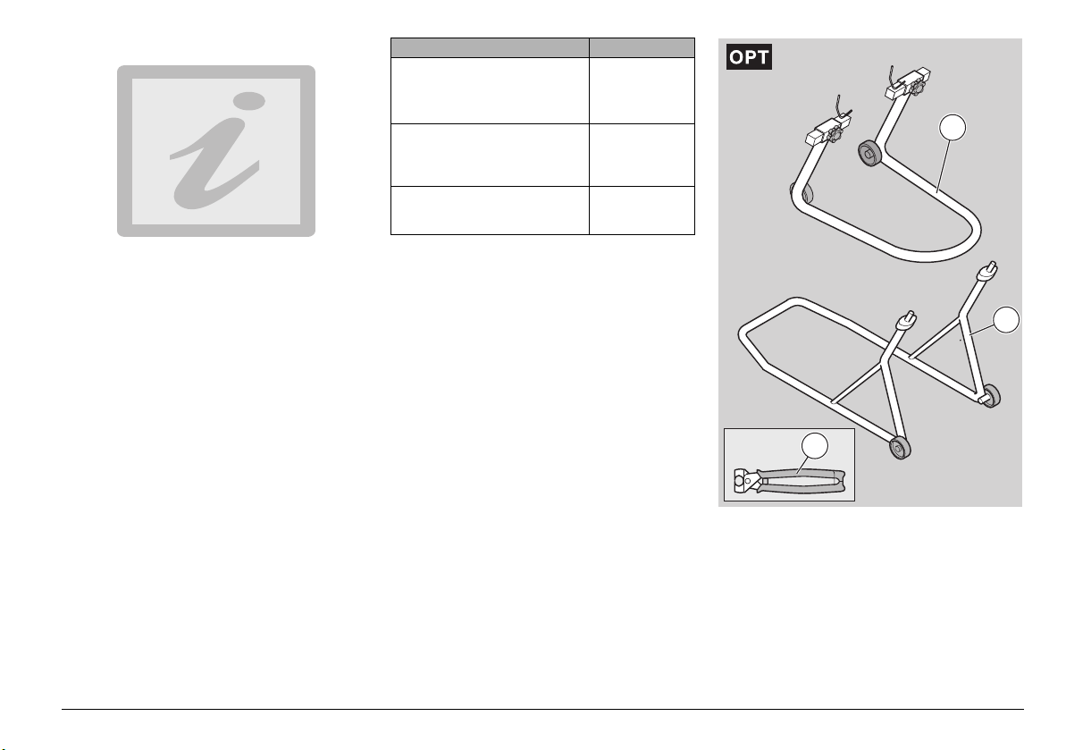
SPECIAL TOOLS J
To perform some specific operations, it is
advisable to use the following special tools
(to be requested to an aprilia Authorised
Dealer):
Tool Operations
Rear support stand (1), see
page 67 (POSITIONING THE
VEHICLE ON THE REAR
SUPPORT STAND J).
Rear wheel
disassembly.
Drive chain
adjustment.
Front support stand (2), see
page 67 (POSITIONING THE
VEHICLE ON THE FRONT
SUPPORT STAND J).
Front wheel
disassembly.
Click clamp (3) installation
pliers, see page 60 (CLICK
CLAMPS).
Click clamp
installation.
1
2
3
Loading...