


 Loading...
Apple Technician Guide
Xserve (Early 2009)
Updated: 2010-06-28

Apple Inc.
© 2009 Apple Inc. All rights reserved.
Under the copyright laws, this document may not be copied, in whole or in part, without the written consent of Apple.
Every effort has been made to ensure that the information in this document is accurate. Apple is not responsible for printing or clerical errors.
Apple
1 Infinite Loop Cupertino, CA 95014-2084 USA
+ 1 408 996 1010 www.apple.com
Apple, the Apple logo, Mac, and Macintosh are trademarks of Apple Inc., registered in the U.S. and other countries.
Xserve (Early 2009)
Contents
Basics
Overview 9
Front View 10
Rear View 10
Serial Number Location 11 Hot-Pluggable SATA or SAS Drives 12
How to Identify Singleand Dual-Processor Configurations 13
Troubleshooting
General Troubleshooting 15
Update System Software 15
Emerging Issues 15
Hardware vs. Software 15
Xserve Firmware Updates 16
Memory Configuration 16
Block Diagram 21
Diagnostic LEDs 22
Symptom Charts 31
Startup and Power Issues 31
No Power / Dead Unit |
31 |
|
Burnt Smell or Odor |
34 |
|
Won’t Start Up / No Video/ LED On 36 |
||
Won’t Start Up / No Video/ Activity LEDs Flashing 38 |
||
Intermittent Shutdown 39 |
||
Kernel Panic/System Crashes 41 |
||
Uncategorized Symptom |
43 |
|
Mass Storage 44 |
|
|
Apple Drive Module Read/Write Issue 44 |
||
RAID Battery Not Charging |
58 |
|
Uncategorized Symptom |
60 |
|
Input/Output Devices |
61 |
|
Rear USB Port Does Not Recognize Known Devices |
61 |
Front USB Port Does Not Recognize Known Devices |
62 |
FireWire Port Does Not Recognize Known Devices |
63 |
PCI-E Expansion Card/Slot Not Recognized 64 |
|

Communications 67
Ethernet Port/Device Issues 67
Video 70
Video Distortion 70
No Video 71
Mechanical Issues: Thermal and Enclosure 72
Failed or Fast Fans 72
Take Apart
General Information |
76 |
Orientation 76 |
|
Tools 76 |
|
How to Identify Singleand Dual-Processor Configurations 76 |
|
Mounting in a Rack |
76 |
Icon Legend 77 |
|
Note on Illustrations |
77 |
Apple Drive Module |
78 |
|
||
Removal |
79 |
|
|
|
Replacement |
80 |
|
|
|
Power Supply |
81 |
|
|
|
Removal |
82 |
|
|
|
Replacement |
82 |
|
|
|
Power Supply Blank |
83 |
|
||
Removal |
84 |
|
|
|
Replacement |
84 |
|
|
|
Top Cover |
85 |
|
|
|
Removal |
86 |
|
|
|
Replace |
86 |
|
|
|
Solid State Drive 87 |
|
|
||
Removal |
88 |
|
|
|
Replacement |
88 |
|
|
|
Solid State Drive Cable |
89 |
|||
Removal |
90 |
|
|
|
Replacement |
90 |
|
|
|
Solid State Drive Carrier |
91 |
|||
Removal |
92 |
|
|
|
Replacement |
92 |
|
|
|
Memory 94
Removal 95
Memory Slot Utility 95
Replacement 96
Memory Configuration 96
PCI-E Riser Cards 97
Removal 98
Replacement 98
PCI-E Expansion Cards 99
Removal 100
Replacement 101
Optical Drive 102
Removal 103
Replacement 104
Airflow Duct 105
Removal 106
Replacement 107
Fan Array 108
Removal 109
Replacement 109
Battery 110
Removal 111
Replacement 111
Front Panel Cable 112
Removal 113
Replacement 113
Backplane-to-Logic Board I/O Cable 114
Removal 115
Replacement 115
Optical Drive Cable 117
Removal 118
Replacement 119
Locking Mechanism Rod 120
Removal 121
Replacement 121
Front Bezel Brackets 122
Removal 123
Replacement 123
Front Bezel Assembly 124
Removal 125

Replacement 126
Front Panel Buttons 127
Removal 128
Replacement 128
Light Pipe 129
Removal 130
Replacement 130
Front Panel Board 131
Removal 132
Replacement 132
Drive Interconnect Backplane 133
Removal 134
Replacement 134
Xserve RAID Card 136
Removal 137
Replacement 138
Power Distribution Board 139
Removal 140
Replacement 140
Power Distribution Board Cable 141
Removal 142
Replacement 142
Xserve RAID Card Battery 143
Removal 144
Replacement 144
Processor Heat Sink 145
Removal 146
Replacement 148
Processor 149
Removal 150
Replacement 151
Video Mezzanine Card 153
Removal 154
Replacement 154
Logic Board 155
Removal 156
Replacement 158
Rear ID Button 159
Removal 160
Replacement 160
ID Tab 161
Removal 162
Replacement 162
Enclosure 163
Removal 164
Replacement 164
Views
Exploded View 166
Feedback 168

Apple Technician Guide
Basics
Xserve (Early 2009)
© 2009 Apple Inc. All rights reserved.
Overview
The Xserve (Early 2009) rack-optimized server features single or dual Quad-Core Intel Xeon “Nehalem” processors, integrated memory controllers featuring up to 12 DIMMs of 1066MHz DDR3 ECC RAM, three hot-plug drive bays supporting SATA or SAS Apple Drive Modules, support for a Solid-State Drive (SSD) boot drive, dual x16 PCI Express 2.0 slots, NVIDIA GeForce GT 120 graphics subsystem and integrated lights-out management.
Identifying Features
The main features and service differences include:
•single and dual Intel Xeon “Nehalem” processors
•6 or 12 DIMM slots depending on processor configuration
•Solid-State Drive Support
•Mini DisplayPort connector on rear panel
2010-06-28 |
Xserve (Early 2009) Basics — Overview 9 |
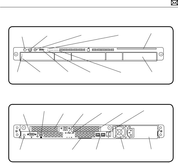
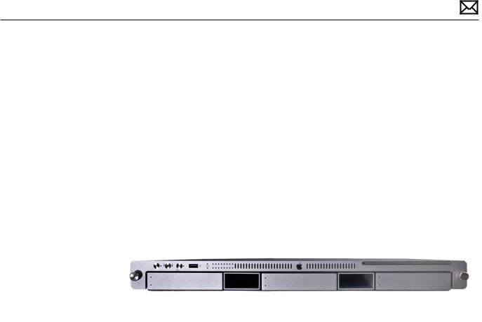
Front View
On/standby button |
Enclosure lock |
System identifier |
Ethernet link light |
Optical drive |
||
and light |
and status light |
button/light |
(Port 2) |
|
||
|
|
|
|
|
|
|
|
|
|
|
|
|
|
Drive module |
Drive module |
USB 2.0 |
Ethernet link light |
System activity |
Drive module |
status light |
activity light |
port |
(Port 1) |
lights |
bays (3) |
Rear View
Serial console |
Mini DisplayPort |
Expansion |
Ethernet |
|
Ethernet |
Expansion |
USB 2.0 ports (2) |
|||||||||
port |
|
slot 2 |
port 2 |
|
|
port 1 |
slot 1 |
|
|
|||||||
|
|
|
|
|
|
|
|
|
|
|
|
|
|
|
|
|
|
|
|
|
|
|
|
|
|
|
|
|
|
|
|
|
|
|
|
|
|
|
|
|
|
|
|
|
|
|
|
|
|
|
|
|
|
|
|
|
|
|
|
|
|
|
|
|
|
|
|
|
|
|
|
|
|
|
|
|
|
|
|
|
|
|
|
|
|
|
|
|
|
|
|
|
|
|
|
|
|
|
|
|
|
|
|
|
|
|
|
|
|
|
|
|
|
|
|
|
|
|
System identifier |
System information tag |
FireWire 800 |
Power supply |
Power supply |
button/light |
(pullout tab) |
ports (2) |
bay 1 |
bay 2 |
2010-06-28 |
Xserve (Early 2009) Basics — Overview 10 |
Serial Number Location
The serial number is located at the rear of the unit: on the ID Tab.
2010-06-28 |
Xserve (Early 2009) Basics — Overview 11 |
Hot-Pluggable SATA or SAS Drives
The server includes three hard drive bays at the front of the Xserve. All bays support Apple qualified hot-pluggable Apple Serial ATA (SATA) or Serial Attached SCSI (SAS) drive modules. Xserve drive bays support qualified Apple Drive Modules with Apple qualified hard drives and firmware only. Drive bays not configured with an Apple Drive Module ship with a nonfunctional blank drive carrier which do not support third-party hard drive installation.
Drive bays are numbered 1-3, beginning with the far left bay. The drive installed in bay 1 is the boot drive and should have the operating system installed on it. Xserve’s configured with a Solid-State Drive (SSD) will contain the Mac OS X Server operating system and function as the boot drive.
You can replace or install hard drives while the Xserve is running; you do not need to shutdown or open the Xserve first, but you may need to dismount the drive from the Xserve OS beforehand. A status light on the front of each drive indicates when it is safe to remove the drive without losing data. For more information, see “Apple Drive Module” in the Take Apart chapter.
Solid-State Drive
The server may include an optional Solid-State Drive. The drive contains the Mac OS X Server operating system as the boot drive for the Xserve.
2010-06-28 |
Xserve (Early 2009) Basics — Overview 12 |

Power Supply Redundancy
The Xserve (Early 2009) supports up to two power supply modules for redundancy. There are two power supply bays in the rear of the enclosure. You can replace or install a power supply from the back panel without removing the Xserve from the rack. If the Xserve has two power supplies, they are hot-swappable; the Xserve will continue to operate using only one supply while the second is removed. For more information about removing or installing power supply modules, see “Power Supply” in the Take Apart chapter.
How to Identify Singleand Dual-Processor Configurations
To identify the configuration of an Xserve (Early 2009) computer, check the code on the computer’s ID Tab, which is located on the computer’s back panel. See “Serial Number Location.”
There are three options for identifying single and dual processor configurations:
•Quad-Core Xserve (Early 2009): Single processor logic board with 6DIMM slots, and one large heat sink
•8-Core Xserve (Early 2009): Dual processor logic board with 12 DIMM slots, and two large heat sinks:
•Quad-Core Xserve (Early 2009): Single processor logic board, 12 DIMM slots and one large heat sink. This option is present only when a single-processor logic board has previously been replaced via the Xserve service parts kit.
2010-06-28 |
Xserve (Early 2009) Basics — Overview 13 |

Apple Technician Guide
Troubleshooting
Xserve (Early 2009)
© 2009 Apple Inc. All rights reserved.
General Troubleshooting
Update System Software
Important: Whenever possible before beginning troubleshooting, ensure the latest software and firmware updates have been applied.
Troubleshooting Theory
For general information on troubleshooting theory, refer to:
http://service.info.apple.com/service_training/en/006/troubleshoot/index.php?page=intro
Emerging Issues
For the latest on troubleshooting issues, refer to:
http://support.apple.com/kb/index?page=search&q=khot%20Xserve%20Emerging%20 Issue
Hardware vs. Software
For information on how to isolate a hardware issue from a software issue, refer to:
http://support.apple.com/kb/TS1388
TS1394—Mac OS X: Troubleshooting installation and software updates <http://support.apple. com/kb/TS1394>
HT2956—Troubleshooting Mac OS X installation from CD or DVD <http://support.apple.com/ kb/HT2956>
For information on how to troubleshoot a software issue, refer to:
HT1199—Mac OS X: How to troubleshoot a software issue <http://support.apple.com/kb/ HT1199>
HT1219—Xserve, Xserve RAID: Apple Drive Module (ADM) compatibility <http://support.apple. com/kb/HT1219>
2010-06-28 |
Xserve (Early 2009) General Troubleshooting — Update System Software 15 |

Xserve Firmware Updates
Firmware is the name given to software that is written into memory circuits, such as flash memory, that will hold the software code indefinitely, even when power is removed from the hardware. Firmware on Intel Mac computers is designed to be updated if necessary through a software update.
EFI and SMC firmware is stored on the Xserve (Early 2009) backplane board. EFI firmware updates update the Boot ROM, and SMC updates update the System Management Controller firmware. The SMC manages fans and other environmental parameters that are independent of the Boot ROM.
Firmware symptoms can be easily mistaken for hardware issues (e.g., overheating issues, fan noise issues, etc.). Always check both EFI and SMC firmware versions and update if necessary before replacing any hardware components.
The following lists describe the type of symptoms that may be resolved by updating the EFI and SMC firmware.
Symptoms that may be resolved by updating EFI firmware:
•Cannot eject media (various conditions)
•No video on start up
•Not waking or sleeping when expected
•Bad media taking too long to eject (including holding mouse button down at startup taking minutes to eject)
Symptoms that may be resolved by updating SMC firmware:
•Fan related behavior (excessive speed or noise)
•Loud audible clicking from some fans
•Thermal shut down or warnings
•Diagnostics reporting failures
•Sleep/wake issues
•Intermittent shut down
•SMC causes bad/missing ambient sensor to cause the computer to go to sleep
•Hangs, black screen on restart from Windows
Please follow the steps outlined in KnowledgeBase article HT2013,“About Firmware Updates for Xserve,” to perform an EFI and/or SMC firmware update. Information about firmware versions for Intel Macs can be found in KnowledgeBase article HT1237,“Mac OS X:Firmware Updates for Intel-based Macs.”
Memory Configuration
Xserve (Early 2009) comes with a minimum of 3 GB of 1066MHz DDR3 ECC memory, installed as three 1 GB unbuffered dual inline memory modules (UDIMMs).
2010-06-28 |
Xserve (Early 2009) General Troubleshooting — Xserve Firmware Updates 16 |
DIMMs must fit these specifications:
•PC3-8500,1066 MHz, DDR3 SDRAM UDIMMs
•72-bit wide, 240-pin modules
•36 memory ICs maximum per UDIMM
•Error-correcting code (ECC)
For proper operation of Xserve (Early 2009) computers, Apple recommends using only Appleapproved DIMMs. Refer to GSX for Apple DIMM service part numbers. Memory from older Xserve computers is not compatible with Xserve (Early 2009).
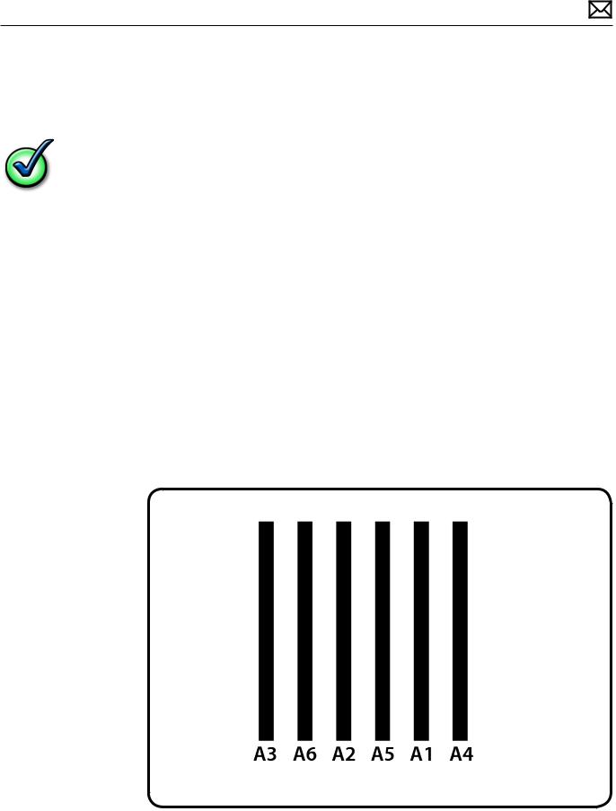
Single Processor
Single-processor (quad-core) computers have six memory slots. You can install 1 GB, 2 GB or 4GB DIMMs for a total of up to 24 GB of memory.
You can install different size DIMMs in Xserve (Early 2009). However, for best performance, Apple recommends you install equal-size DIMMs (all 1, 2 or 4GB) filling the slots in the order listed in this table.
|
If you have |
Fill these slots |
|
Three DIMMs |
A1, A2, and A3 |
|
Four DIMMs |
A1, A2, A3, and A4 |
|
Five DIMMs |
A1, A2, A3, A4, and A5 |
|
Six DIMMs |
A1, A2, A3, A4, A5, and A6 |
See also “Memory Slot Utility” below. |
|
|
2010-06-28 |
Xserve (Early 2009) General Troubleshooting — Memory Configuration 17 |
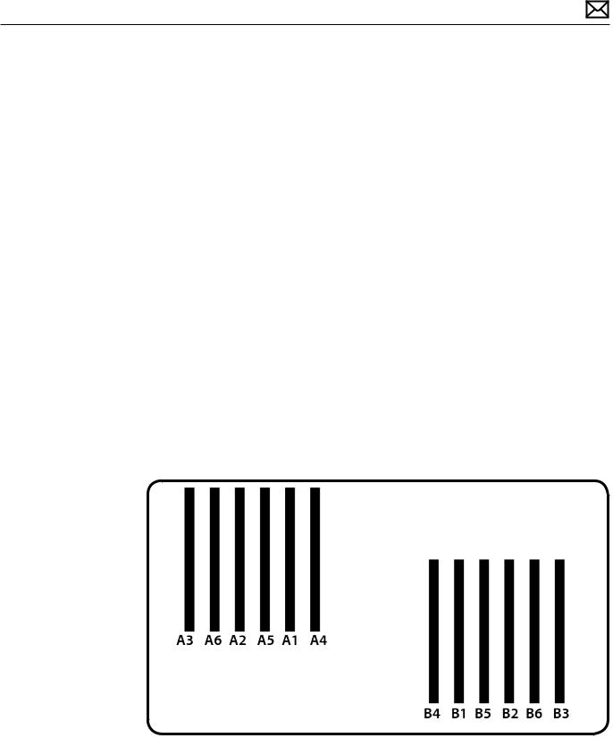
Dual Processor
Dual-processor (eight-core) computers have twelve memory slots. You can install 1 GB, 2 GB, or 4 GB DIMMs for a total of up to 48 GB of memory.
You can install different size DIMMs. in Xserve (Early 2009) However, for best performance, Apple recommends you install equal-size DIMMs (all 1, 2, or 4 GB) filling the slots in the order listed in this table.
If you have |
Fill in these slots |
Three DIMMs |
A1, A2, and A3 |
Four DIMMs |
A1, A2, and B1, B2 |
Five DIMMs |
A1, A2, A3 and B1, B2 |
Six DIMMs |
A1, A2, A3 and B1, B2, B3 |
Seven DIMMs |
A1, A2, A3, A4 and B1, B2, B3 |
Eight DIMMs |
A1, A2, A3, A4 and B1, B2, B3, B4 |
Nine DIMMs |
A1, A2, A3, A4, A5 and B1, B2, B3, B4 |
Ten DIMMs |
A1, A2, A3, A4, A5, A6 and B1, B2, B3, B4 |
Eleven DIMMs |
A1, A2, A3, A4, A5, A6 and B1, B2, B3, B4, B5 |
Twelve DIMMs |
A1, A2, A3, A4, A5, A6 and B1, B2, B3, B4, B5, B6 |
See also “Memory Slot Utility” below.
2010-06-28 |
Xserve (Early 2009) General Troubleshooting — Memory Configuration 18 |
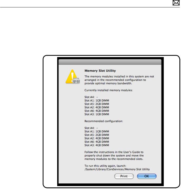
Memory Slot Utility
If you install different size DIMMs in single-processor or dual-processor computers, follow the order in the tables above. If the DIMM configuration you install doesn’t provide optimized performance, the Memory Slot Utility will appear on screen and recommend an improved configuration. To use the Memory Slot Utility again, go to /System/Library/Core Services.
Example of Memory Slot Utility Screen for Single-Processor Computer
2010-06-28 |
Xserve (Early 2009) General Troubleshooting — Memory Configuration 19 |
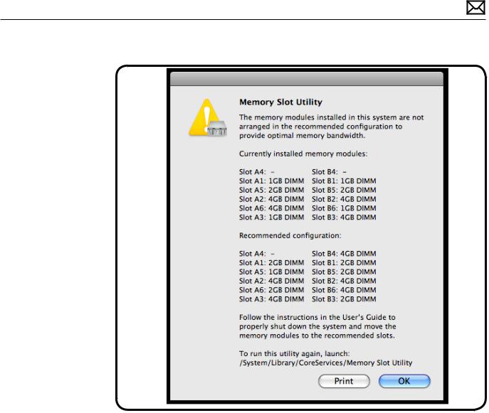
Example of Memory Slot Utility Screen for Dual-Processor Computer
2010-06-28 |
Xserve (Early 2009) General Troubleshooting — Memory Configuration 20 |

Block Diagram
2010-06-28 |
Xserve (Early 2009) General Troubleshooting — Block Diagram 21 |
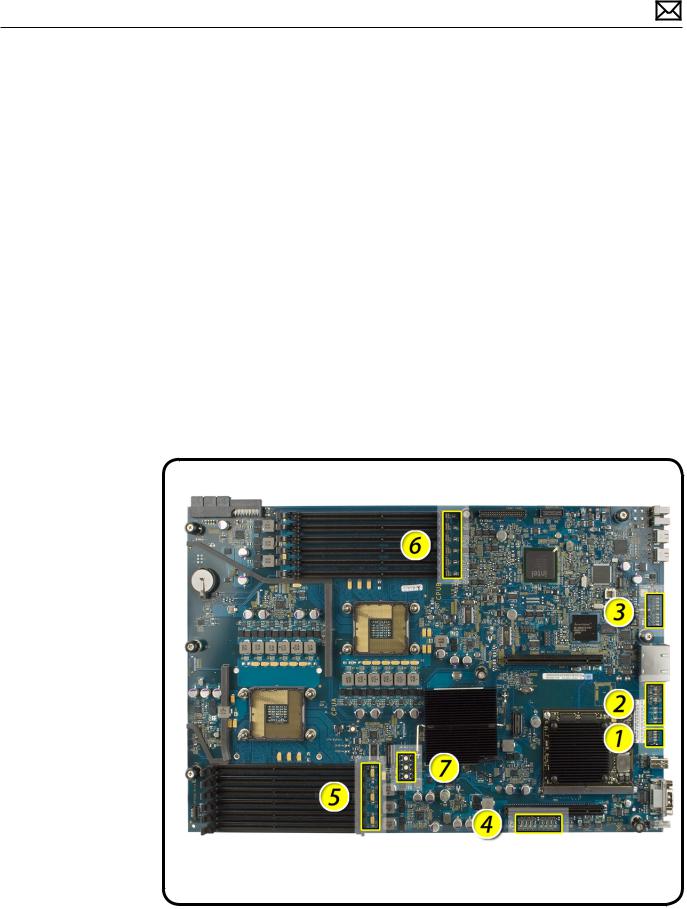
Diagnostic LEDs
Logic Board Diagnostic LEDs
The Xserve (Early 2009) logic board includes a set of LEDs to help service providers troubleshoot the computer. The LEDs are located on the logic board below the DIMM connectors, at the rear of the unit, to the left side of the unit (looking from the back), and on the Drive Interconnect Backplane or Xserve RAID Card.
Some tips:
•You must remove the unit from its rack and place it on a sold surface with its cover removed in order to view these LEDs. Most internal diagnostic LEDs are only enabled to come on when the cover is removed (memory DIMM LEDs remain ON even with the cover in place).
•Do not attempt to troubleshoot the unit solely by these LEDs alone. Use this information to guide your troubleshooting, not lead it.
If a specific error condition exists, there should be corresponding LED evidence to help verify and isolate the issue. However, it is not possible to deduce a fault or isolate a specific symptom solely by examining these LEDs out of context.
2010-06-28 |
Xserve (Early 2009) General Troubleshooting — Diagnostic LEDs 22 |
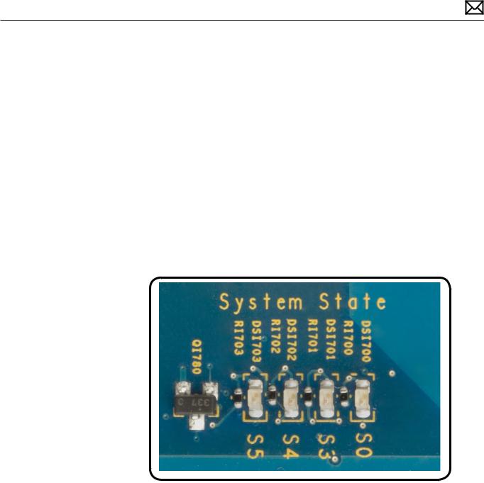
1. System State LEDs
Use the following table to interpret the LEDs.
Location |
Name |
Color |
Nominal |
Indicates |
S0 |
Power ON |
Green |
On; off when |
System is |
|
|
|
in standby |
running |
|
|
|
mode |
|
S3 |
Sleep |
Green |
Off, on when |
System is in |
|
|
|
Xserve is in |
sleep mode |
|
|
|
sleep mode |
|
S5 |
Standby |
Green |
Off; on when |
Standby |
|
|
|
Xserve is in |
mode, |
|
|
|
standby |
illuminates |
|
|
|
|
when AC |
|
|
|
|
power is |
|
|
|
|
attached |
2010-06-28 |
Xserve (Early 2009) General Troubleshooting — Diagnostic LEDs 23 |
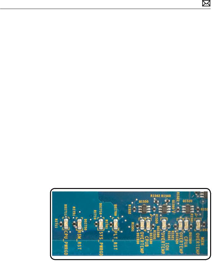
2. CPU Error LEDs
Use the following table to interpret the LEDs.
Location |
Color |
Nominal |
Indicates |
CPU_PWRGD |
Green |
Off; on to indicate |
Power chain in hardware |
|
|
hardware power has |
|
|
|
passed |
|
RSM_RST |
Yellow, Red |
Off |
Fault preventing CPU from |
|
|
|
executing instructions |
SYS_PWRGD |
Green |
On at power-on to |
Power chain in hardware |
|
|
indicate power has |
|
|
|
passed |
|
PLT_RST |
Red |
Off; on Yellow at |
Platform reset |
|
|
power on |
|
CPU B OVERTEMP |
Red |
Off; on if CPU B core |
Temperature of CPU B core |
|
|
exceeds normal |
status |
|
|
temperature |
|
IOH OVERTEMP |
Red |
Off; on if IOH exceeds |
Temperature of IOH status |
|
|
normal temperature |
|
CPU A OVERTEMP |
Red |
Off; on if CPU A core |
Temperature of CPU A core |
|
|
exceeds normal |
status |
|
|
temperature |
|
|
|
|
|
MXM OVERTEMP |
Red |
Off; on if MXM video |
Temperature of MXM video |
|
|
card exceeds normal |
card status |
|
|
temperature |
|
|
|
|
|
2010-06-28 |
Xserve (Early 2009) General Troubleshooting — Diagnostic LEDs 24 |

Platform Reset
Normally remains on during standby. This LED flashes on (yellow) briefly at power-on. LED should turn off as system powers up and begins to execute instructions.
Overtemp LEDs
Normally off. These LEDs come on if an error occurs.
If LED is solidly on, it may indicate a processor over-temperature condition. Initial processor over-temperature can cause symptoms such as sluggish computer performance. Chronic processor over-temperature can cause the computer to hang completely.
Troubleshooting:
•Verify proper heatsink installation.
•Verify all fans are operating properly, especially the fan array.
•If both overtemp LEDs come on immediately when the computer is turned on, a faulty power supply could be one cause of this behavior. Replace power supply.
•Try swapping CPU A and CPU B locations. If the CPU Error LED follows the CPU, replace that CPU.
3. EFI POST (Power On Self Test) LEDs
This group of eight LEDs are arranged into two sets of four LEDs, representing a binary code that only has any significance during the short time between power-on and the unit begins to boot the OS, while the CPU is executing EFI code only. At no other time should these LEDs be used or interpreted to mean anything meaningful.
The code is more easily described as two Hexadecimal digits ranging from $00 to $FF, to make it easier to list and compare during troubleshooting. Each ONE represents an LED that is ON, and each ZERO represents an LED that is OFF
Normal power-up LED sequence:
•The sequence of codes below is typical in the first few seconds of a functioning unit’s boot cycle, immediately following power-on, during the EFI phase of startup.
•If your system is not booting you should check these LEDs closely to verify the sequence of codes has been executed in addition to your normal troubleshooting steps. Each code will only remain ON GREEN for a split-second each. The entire sequence takes only a few seconds to progress through.
•To see this sequence, power-on the unit (use the remote power on/off button on the logic board) while holding down the option key on an attached USB keyboard, to invoke the EFI startup manager and prevent the unit from leaving EFI and booting into any OS. Do this as you watch these LEDs as they progress through the following sequence:
Begin (power-on)
2010-06-28 |
Xserve (Early 2009) General Troubleshooting — Diagnostic LEDs 25 |
$Bx = 1 0 1 1 X X X X = All $Bx codes below are memory init codes (x may be any code 0 - F)
$BF = 1 0 0 1 1 1 1 1 = If the unit does not progress past any $Bx memory init codes, this could indicate a memory issue regardless of whether DIMM diagnostic error LEDs are ON or not.
$12 = 0 0 0 1 0 0 1 0 = After memory initialization has successfully completed
$51 = 0 1 0 1 0 0 0 1 = Video driver enabled beyond this point. Attached display should be displaying an image now. If not, this may indicate a graphics card issue.
$F9 = 1 1 1 1 1 0 0 1 = EFI finished and passed on control to OS boot loader
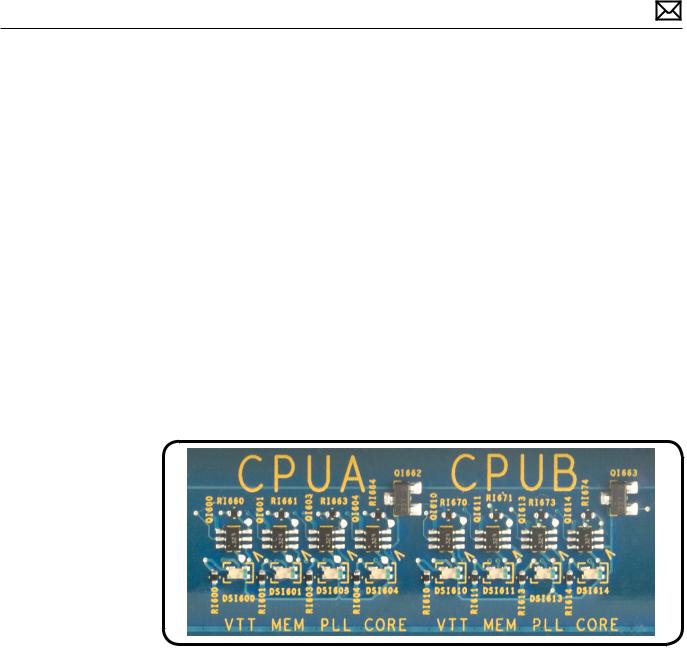
4. CPU Voltage LEDs
This group of LEDs will normally FLASH RED briefly during power-on, then should normally remain ON solidly GREEN when all voltage regulators are functioning properly to provide voltages to CPU A and CPU B, as well as IOH.
If any of these LEDs remain ON RED, this indicates that the corresponding voltage regulator is enabled but not providing any voltage output.
In single processor units the LED group for the second processor are not present.
2010-06-28 |
Xserve (Early 2009) General Troubleshooting — Diagnostic LEDs 26 |
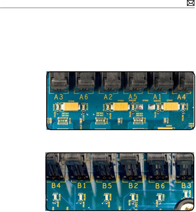
5 & 6. Memory Diagnostic LEDs (A1 - A6 and B1 - B6)
This group of LEDs will normally remain OFF during power-on and throughout normal operation. If any of these LEDs come ON RED, this indicates that the corresponding DIMM (or its slot) may be faulty. To verify whether the fault lies with the DIMM or the slot, power down the unit and move the DIMM to another slot. If the DIMM is faulty, the LED adjacent to its new slot should come ON RED when power is reapplied. If a known-good DIMM is installed in the suspect slot and the LED adjacent to this slot should come ON RED , this may indicate a faulty DIMM slot on the logic board.
How to Troubleshoot Memory LEDs
1.Remove and reseat DIMM
2.Restart computer. If associated LED is no longer illuminated, issue is resolved
3.If associated LED remains illuminated, replace DIMM with new DIMM
4.Restart computer and verify LED is no longer illuminated
2010-06-28 |
Xserve (Early 2009) General Troubleshooting — Diagnostic LEDs 27 |

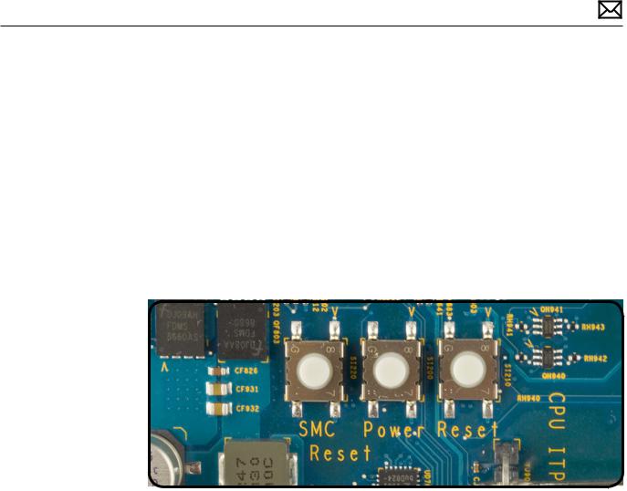
7. Reset Buttons
System Management Controller (SMC) Reset
The System Management Controller (SMC) is a chip on the logic board that controls all power functions for the Xserve. If the Xserve is experiencing any power issue, resetting the SMC may resolve it. The SMC controls several functions, including:
•Telling the Xserve when to turn on, turn off, sleep, wake, idle, and so forth
•Handling system resets from various commands
•Controlling the fans
It is also recommended that the SMC be reset on any new logic board after it is installed as part of a repair.
Note that resetting the SMC does not reset the PRAM. Resetting the SMC will not resolve issues in which the Xserve is unresponsive—in these situations, restarting the Xserve will generally suffice.
If the Xserve isn’t responding, perform these steps one at a time, in the following order, until the issue has been resolved:
1.Force Quit (Option-Command-Escape)
2.Restart (Control-Command-Power)
3.Force Shut Down (press the power button for 10 seconds)
4.Remove the Xserve from the rack (if applicable)
5.Remove the Top Case
6.Press the SMC Reset button on the logic board
Resetting the SMC can resolve some Xserve issues such as not starting up, not displaying video, sleep issues, fan noise issues, and so forth. If the Xserve still exhibits these types of issues after you’ve restarted the Xserve, try resetting the SMC. There are two ways to reset the SMC on the Xserve.
System Management Control (SMC) Reset in Rack
1.Shut Down the Xserve, either locally or using remote commands (or if the Xserve is not responding, hold the power button until it turns off).
2.Unplug the AC power cord.
3.Wait at least 15 seconds.
4.Plug the power cord back in, making sure the power button is not being pressed at the time.
2010-06-28 |
Xserve (Early 2009) General Troubleshooting — Diagnostic LEDs 28 |
5. Press the power button to start up the Xserve.
Power ON / OFF Button
Behaves exactly like the front panel power button, and can be used as an alternate way to turn the unit on and off if needed.
Reset Buttons
When pressed, resets CPUs regardless of what is currently running. This reset overrides all software processes and restarts the system. Use with caution as this form of reset may corrupt software or files on a drive.
Drive Interconnect Backplane LEDs
Note: The following information describes the diagnostic LEDs present on the interconnect backplane.
This group of eight LEDs are arranged into two sets of four LEDs, representing information about the SATA / SAS communication between the drive controller channels on the drive interconnect backplane and the drive modules themselves. The optional SSD drive does not have a representative LED on this board.
There is also a ‘heartbeat’ LED on this board which starts flashing ON GREEN and OFF when EFI loads immediately after power-on and continues to flash ON and OFF during normal operation.
The first group of four LEDs indicates activity for the four I/O channels corresponding to the three drive bays. Since there are only three drive bays, the fourth I/O channel and LED are not used and should remain OFF during normal operation.
The second group of four LEDs indicates that the controller has recognized that a drive module is present and connected. These LEDs are normally solidly ON GREEN when no drive is present, and turn OFF when a drive module has been inserted into the corresponding drive
2010-06-28 |
Xserve (Early 2009) General Troubleshooting — Diagnostic LEDs 29 |

bay and the controller has recognized this event. The LED will turn ON GREEN again when the corresponding drive module has been removed from its bay.
Since there are only three drive bays, the fourth I/O channel and LED are not used and should remain ON GREEN during normal operation.
When you power-on the system, you should see the following activity sequence on these LEDs:
1.The entire group of eight LEDs should come ON solid GREEN when power is applied and remain on for a few seconds.
2.The heartbeat LED begins flashing when EFI loads in the first few second after power-on. The first group of four activity LEDs should now turn OFF. The second group of four ‘drive present’ LEDs should remain on for a few more seconds.
3.The second group of four ‘drive present’ LEDs should each turn OFF as the controller scans and recognizes each connected drive module in turn, from bay 1 to bay 3 in order. The fourth LED should remain ON since no drive is present on the fourth I/O channel.
4.Beyond this point, the only LEDs that should be flashing are among the first group of four drive activity LEDs, to indicate drive activity between a corresponding drive module, such as the boot drive module booting the OS, and the drive controller.
2010-06-28 |
Xserve (Early 2009) General Troubleshooting — Diagnostic LEDs 30 |
Loading...