


 Loading...
Service Source
Mac Pro
Updated: 4 March 2008
© 2006 Apple Computer, Inc. All rights reserved.

Mac Pro
Contents
Basics
Overview 6
Serial Number Location 7
Take Apart
General Information 9
Opening the Computer 10 Hard Drives 12
Optical Drive Carrier and Optical Drives 15 Memory (FB-DIMMs) and Memory Riser Cards 19 PCI Express/Graphics Card 23
Power Supply 29 Power Supply Fan 38 AirPort Extreme Card 47 Bluetooth Card 50 Battery 52
Processor Heatsink Cover 54 Front Fan Assembly 59
Mac Pro RAID Card & Battery 62 Processor Heatsinks 68
Memory Cage with Rear Fan 73 Processors 76
ii

Speaker Assembly |
83 |
|
|
|
||
USB Cable |
87 |
|
|
|
|
|
Logic Board |
90 |
|
|
|
|
|
Front Panel Board |
100 |
|
|
|||
Power Button |
105 |
|
|
|
|
|
AirPort Antenna Board with Cables |
110 |
|||||
Optical Drive Power Cable |
114 |
|
||||
Optical Drive Data (Ribbon) Cable |
117 |
|||||
Ambient Board |
120 |
|
|
|
||
Ambient Board Cable |
122 |
|
|
|||
Bluetooth Antenna Board and Cable |
124 |
|||||
Hard Drive Cable Harness |
127 |
|
||||
Hard Drive Temperature Sensor Cable 130 |
||||||
Hard Drive Temperature Sensor 133 |
||||||
Power Cable Harness |
136 |
|
|
|||
Troubleshooting
General Information |
140 |
|
Memory 140 |
|
|
PCI Express Cards 141 |
|
|
Internal Cabling Matrix 141 |
||
Thermal Calibration |
143 |
|
Block Diagram 144 |
|
|
Resetting the Logic Board |
145 |
|
Power-On Self Test:RAM and Processor Verification 146 |
||
Diagnostic LEDs 147 |
|
|
Power Supply Verification |
152 |
|
Mac Pro Firmware Updates |
152 |
|
Symptom Charts |
154 |
How to Use the Symptom Charts 154 |
|
Startup Failures |
154 |
Fans 157 |
|
Other Failures |
158 |
iii

Upgrades
AirPort Extreme Card 162
Bluetooth Card 165
PCI Express/Graphics Card 167
Views
Exploded View 172
External Views 174
Screw Matrix 176
iv

Service Source
Basics
Mac Pro
© 2006 Apple Computer, Inc. All rights reserved.
 Overview
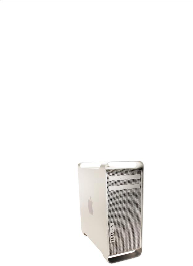
The Mac Pro form factor is similar to that of earlier Power Mac G5 models. However, the Mac Pro includes several new hardware features, including:
•Two dual-core Intel processors
All Mac Pro models have two dual-core Intel Xeon processors, effectively making them quad processor computers.
•FB-DIMM memory supporting ECC and up to 16 GB of RAM
Higher performance memory with support for error correction and greater capacity means more room to grow when using high-performance computing applications.
•Four internal hard drives
Mac Pro supports up to four serial ATA (SATA) hard drives in easy-to-install drive carriers.
•Two optical drives
Mac Pro offers support for two cable-select optical drives
In addition to the features above, Mac Pro includes logic board diagnostic LEDs that help you better diagnose hardware issues.
Mac Pro Basics 6
 Serial Number Location
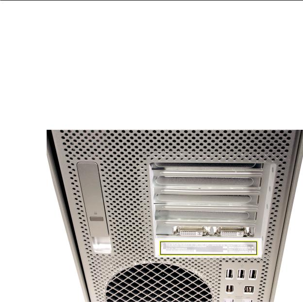
To identify a particular Mac Pro computer, check the computer’s serial number.You can find the serial number within the model’s configuration label, which is located on the computer’s back panel directly below the video ports.
Mac Pro Basics 7
Service Source
Take Apart
Mac Pro
© 2006 Apple Computer, Inc. All rights reserved.

 General Information
Orientation
For most take-apart procedures, it is recommended that you lay the computer on its side before removing or installing the part. For proper operation, however, Apple recommends that the unit be run in the upright position. The computer should never be operated on its side with the access panel facing down.
Tools
The following tools are required to service all configurations of the computer:
•Long-handled magnetized Phillips #1 screwdriver
•Long-handled magnetized 3 mm flathead hex screwdriver
•Short-handled, magnetized 2.5 mm hex wrench
•Flat-blade screwdriver
•Magnetized jewelers Phillips #1 screwdriver
•Magnetized jeweler’s Phillips #0 screwdriver
•Jeweler’s flat-blade screwdriver
•Socket wrench
•Apple Mac Pro wrench (part number 922-8025)
•Needlenose pliers
•Scissors or wire cutters
•Xacto knife
•Nylon probe tool (black stick)
•Tape (for temporarily holding cables out of the way)
•Small mirror (for seeing small boards inside the enclosure)
•Soft cloth (for protecting the enclosure from scratches)
Parts Requiring Enclosure Replacement
The following are not separate, orderable parts. To replace them, you must replace the enclosure.
•Media shelf
•Rear panel latch
Mac Pro Take Apart — General Information 9

 Opening the Computer
Tools
No tools are required for this procedure.
Preliminary Steps
1.Shut down the computer.
Warning: Always shut down the computer before opening it to avoid damaging its internal components or the components you are installing. Do not open the computer or attempt to install items inside it while it is on.
2.Wait 5 to 10 minutes to allow the computer’s internal components to cool.
Warning: After you shut down the system, the internal components can be very hot. You must let the computer cool down before continuing.
3.Unplug all external cables from the computer except the power cord.
4.Touch the metal PCI access covers on the back of the computer to discharge any static electricity from your body.
Important: Always discharge static before you touch any parts or install any components inside the computer. To avoid generating static electricity, do not walk around the room until you have finished working and closed the computer.
5.Unplug the power cord.
Warning: To avoid damaging its internal components or the components you want to install, always unplug the computer before attempting any take-apart procedure.
6.Put on an ESD wrist strap.
Mac Pro — Opening the Computer 10
Procedure
1.Hold the side access panel and lift the latch on the back of the computer.
Warning: The edges of the access panel and the enclosure can be sharp. Be very careful when handling them.
2.Remove the access panel and place it on a flat surface covered by a soft, clean cloth.
Replacement Note: Make sure the latch is in the up position before replacing the access panel. If the latch is down, the access panel will not seat correctly in the enclosure.
Mac Pro — Opening the Computer 11

 Hard Drives
The Mac Pro computer can accommodate four serial ATA (SATA) 3 Gbps hard drives in its four internal hard drive bays. In most configurations, a single hard drive occupies the far left bay
(bay 1).
The hard drives must meet the following specifications:
•Type: SATA 3 Gbps
•Width: 3.9 inches (102 mm)
•Depth: 5.7 inches (147 mm)
•Height: 1.0 inch
Tools
The only tool required for this procedure is a Phillips #1 screwdriver.
Preliminary Steps
Before you begin, open the computer, and lay it on its side with the access side facing up.
Important: Make sure the latch on the back panel is in the up position. When the latch is down, the hard drives and carriers are locked in place and you will not be able to remove them.
Mac Pro Take Apart — Hard Drives 12
Part Location
Procedure
1.Make sure the latch on the back panel is up, so that the drives and carriers are unlocked.
2.Pull the hard drive out of the drive bay.
Mac Pro Take Apart — Hard Drives 13
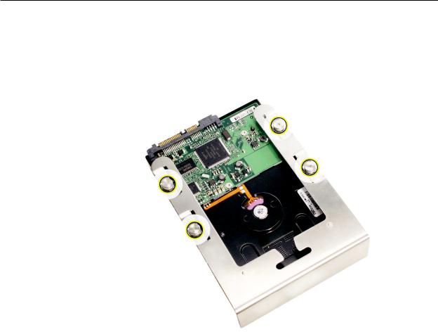
3.If you are replacing the hard drive with a new drive, remove the four screws that mount the drive to the carrier and mount the new drive in the carrier.
Important: Hold the drive by its sides. Be careful not to touch the printed circuit board on the bottom of the drive.
Replacement Note: Slide the carrier and drive over the guides and into the drive bay, until you feel the drive snap into place.
Note: If you install a new (replacement) drive, format it by following these steps:
1.Open Disk Utility and select the drive in the list to the left.
Note: If you are formatting the primary drive, use the Disk Utility program on the Install Disk.
2.Click on the Partition tab.
3.Click on “Options” and verify GUID is selected if this is a bootable drive.
4.Apply the change by clicking on the “Partition” button.
Mac Pro Take Apart — Hard Drives 14
Optical Drive Carrier and
Optical Drives
The Mac Pro computer can accommodate two optical drives in the optical drive bay. If the computer has only one optical drive, it is installed in the top position.
Note: To eject the drives, use the following:
•Top drive: Press the Eject key.
•Bottom drive: Press the Option and Eject keys.
Tools
The only tool required for this procedure is a Phillips #1 screwdriver.
Preliminary Steps
Before you begin, open the computer, and lay it on its side with the access side facing up.
Important: Make sure the latch on the back panel is in the up position. When the latch is down, the optical drives and carrier are locked in place and you will not be able to remove them.
Part Location
Mac Pro Take Apart — Optical Drive Carrier and Optical Drives 15
Procedure
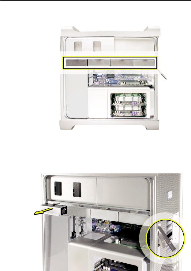
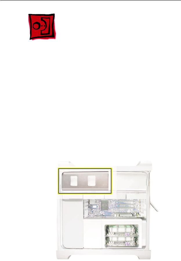
Removing the Optical Drive Carrier and Optical Drives
1.Make sure the latch on the back panel is up, so that the drives and carriers are unlocked.
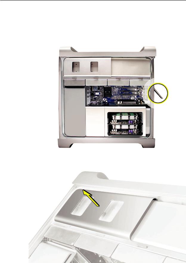
2.Pull the optical drive carrier part way out of the computer.
Mac Pro Take Apart — Optical Drive Carrier and Optical Drives 16
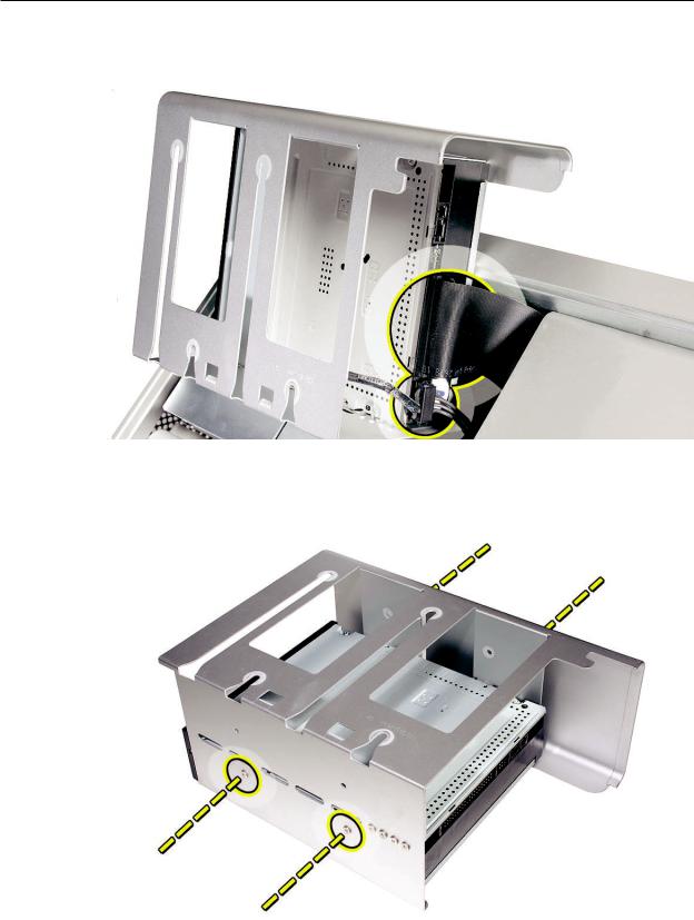
3.Disconnect the power and ribbon cables from the optical drive(s) and remove the carrier.
4.If you are replacing the optical drive with a new optical drive, do the following:
•Remove the four mounting screws and remove the optical drive from the carrier.
•Use the four screws to mount the replacement drive in the carrier.
Note: If you are adding a second drive to the carrier, use the four screws stored on the back of the drive carrier to secure the drive to the carrier.
Mac Pro Take Apart — Optical Drive Carrier and Optical Drives 17
Replacing the Optical Drive Carrier and Optical Drives
Important: Use the original Apple cables that came with the computer when you install or replace the optical drives. If just one optical drive is installed, tuck the cables for the second drive out of the way.
1.Attach the power and ribbon cables to the back of the drive(s).
Important: Attach the connector on the end of the optical drive ribbon cable and the connector in the middle of the optical drive power cable to the top drive. If there is a second drive in the carrier, attach the remaining optical drive ribbon and power connectors to the bottom drive.
2.Slide the optical drive carrier over the guides and into place in the optical drive bay.
Mac Pro Take Apart — Optical Drive Carrier and Optical Drives 18
Memory (FB-DIMMs) and
Memory Riser Cards
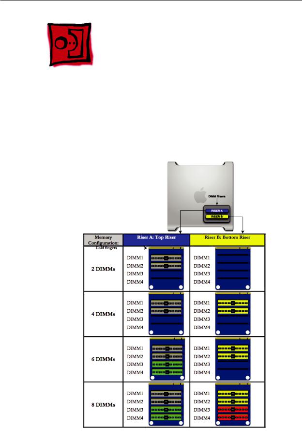
The Mac Pro computer has two memory riser cards with a total of 8 memory slots. On each card, the slots are arranged as two banks of two slots each. The computer comes with a minimum of
1 GB of memory, installed as a pair of 512 MB fully buffered, dual inline memory modules (FB-
DIMMs) in two of the DIMM slots. Additional DIMMs can be installed in the open DIMM slots, as illustrated below.
Note: DIMMs must be installed in pairs of equal size from the same vendor. In the illustration below, DIMMs in one colored pair do not need to match DIMMs in a different colored pair.
Mac Pro Take Apart — Memory (DIMMs) and Memory Riser Cards 19
DIMMs for Mac Pro must fit these specifications:
•667 MHz, FB-DIMMs
•72-bit wide, 240-pin modules
•36 devices maximum per DIMM
•Error-correcting code (ECC)
Memory from older Macintosh computers is not compatible with Mac Pro.
Important: For proper operation of Mac Pro computers, Apple recommends using only Appleapproved Mac Pro FB-DIMMs. Refer to GSX for Apple FB-DIMMs service part numbers.
Tools
No tools are required for this procedure.
Preliminary Steps
Before you begin, open the computer, and lay it on its side with the access side facing up.
Warning: Always wait 5–10 minutes for the computer to cool down before you remove or install memory. The DIMMs may be very hot.
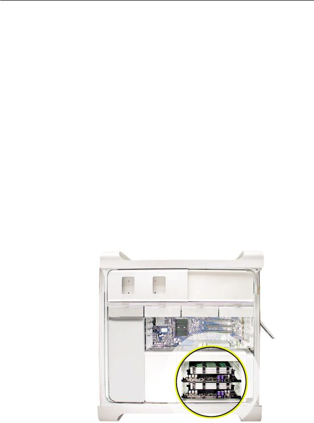
Part Location
Mac Pro Take Apart — Memory (DIMMs) and Memory Riser Cards 20

Procedure
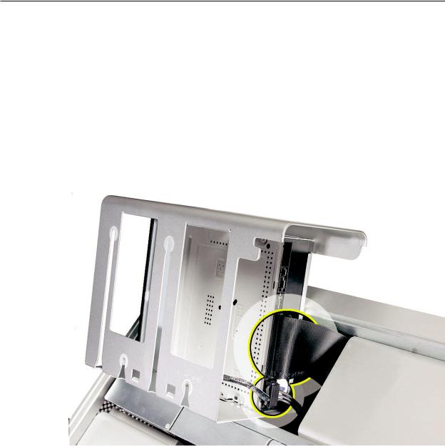
1.Holding the memory riser card by the two finger holes, pull it out of the memory cage and place the card DIMM side up on a soft, clean cloth.
2.Open the ejectors on the DIMM slot by pushing them out to the sides, and remove the DIMM from the riser card.
Mac Pro Take Apart — Memory (DIMMs) and Memory Riser Cards 21
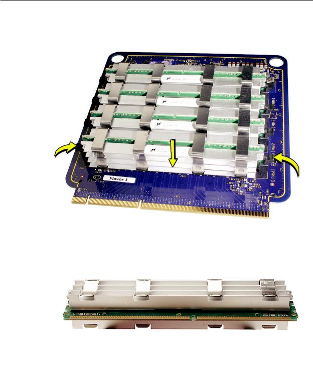
Replacement Note: Align the DIMM in the slot on the riser card and push both ends of the DIMM down until the ejectors snap back up into place.
Warning: FB-DIMMs carry heatsinks on either side of the DIMM. Never attempt to remove the heatsinks from the DIMMs. Doing so could damage the DIMM.
Mac Pro Take Apart — Memory (DIMMs) and Memory Riser Cards 22
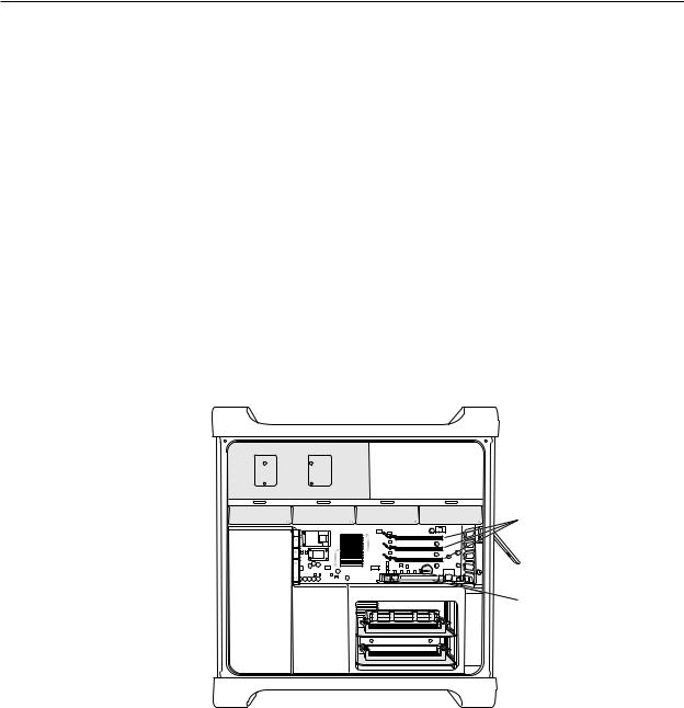
 PCI Express/Graphics Card
The Mac Pro logic board includes one double-wide PCI Express graphics slot and three PCI Express expansion slots, for a total of four slots. The computer comes with a graphics card installed in slot 1. You can install additional PCI Express graphics and expansion cards in the remaining three PCI Express expansion slots.
Important: Graphics cards from previous Power Mac G5 models are not compatible with Mac Pro models. In addition, Mac Pro graphics cards are not compatible with Power Mac G5 models.
Important: Combined maximum power consumption for all four PCI Express slots must not exceed 300 W.
Slots 2–4: PCI Express
Slot 1: Double-wide PCI Express graphics
(graphics card installed)
Note: Port 2 of the ATI Radeon X1900 XT graphics card is compatible with the Apple DVI-to-video adapter. See KnowledgeBase article 304910.
Tools
The only tool required for this procedure is a Phillips #1 screwdriver.
Mac Pro Take Apart — PCI Express/Graphics Card 23
Preliminary Steps
Before you begin, open the computer, and lay it on its side with the access side facing up.
Note: You may also find it helpful to remove the hard drives and carriers and any adjacent PCI Express cards before beginning this procedure.
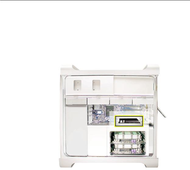
Part Location
Mac Pro Take Apart — PCI Express/Graphics Card 24
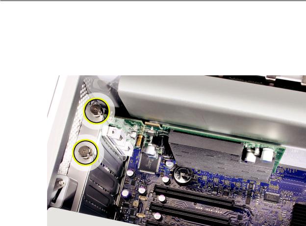
Procedure
This procedure explains how to remove a standard card and a card that includes a booster cable.
Before you can remove either type of card, however, you must first loosen the two captive screws that secure the PCI bracket to the enclosure and remove the bracket.
Warning: When removing or installing a card, handle it only by the edges. Do not touch its connectors or any of the components on the card. Lift the card straight out from the connector to remove it, and insert it straight into the connector to install it. Do not rock the card from side to side and don’t force the card into the slot. Once the replacement card is installed, pull on it gently to check that it is properly connected.
Mac Pro Take Apart — PCI Express/Graphics Card 25
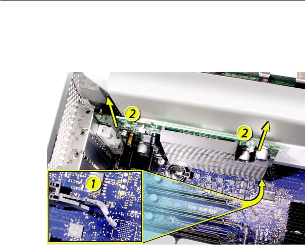
Standard Card
1.Release the small locking clip at the front of the card’s logic board connector by pushing the clip up toward the media shelf.
2.Holding the card by the top corners, pull up the card and remove it from its expansion slot.
Replacement Note: Align the card’s connector with the expansion slot and press until the connector is inserted all the way into the slot. If you’re installing a 12-inch card, make sure the card engages the appropriate slot in the PCI card guide.
•Don’t rock the card from side to side; instead, press the card straight into the slot.
•Don’t force the card. If you meet a lot of resistance, pull the card out. Check the connector and the slot for damage or obstructions, then try inserting the card again.
•Pull the card gently to see if it is properly connected. If it resists and stays in place and its gold connectors are barely visible, the card is connected.
Mac Pro Take Apart — PCI Express/Graphics Card 26
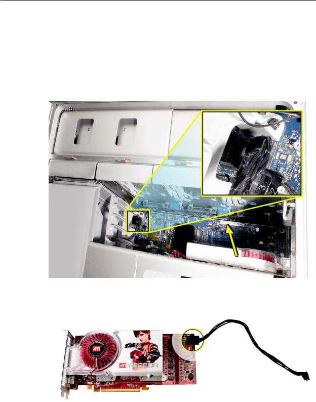
Card with Booster Cable
1.Disconnect the booster cable from the logic board.
2.Release the small locking clip at the front of the card’s logic board connector by pushing the clip up toward the media shelf.
3.Holding the card by the top corners, gently pull up the card and remove it from its expansion slot.
4.If you are replacing the booster cable with a new booster cable, disconnect the cable from the card.
Mac Pro Take Apart — PCI Express/Graphics Card 27
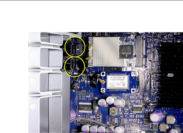
Replacement Note: There are two logic board connectors for booster cables. Connect the booster cable for a card in PCI slot 1 to the lower connector. Connect the booster cable for a card in PCI slot 2 to the upper connector.
Mac Pro Take Apart — PCI Express/Graphics Card 28
 Power Supply
Tools
The only tool required for this procedure is a magnetized 2.5 mm hex wrench.You may also find a flat-blade screwdriver helpful in releasing some cable connectors.
Preliminary Steps
Before you begin, open the computer, lay it on its side with the access side facing up, and remove the following:
•Hard drives and hard drive carriers in drive bays 3 and 4
•Optical drive carrier and optical drives
•Any PCI Express cards that block access to the power supply mounting screws
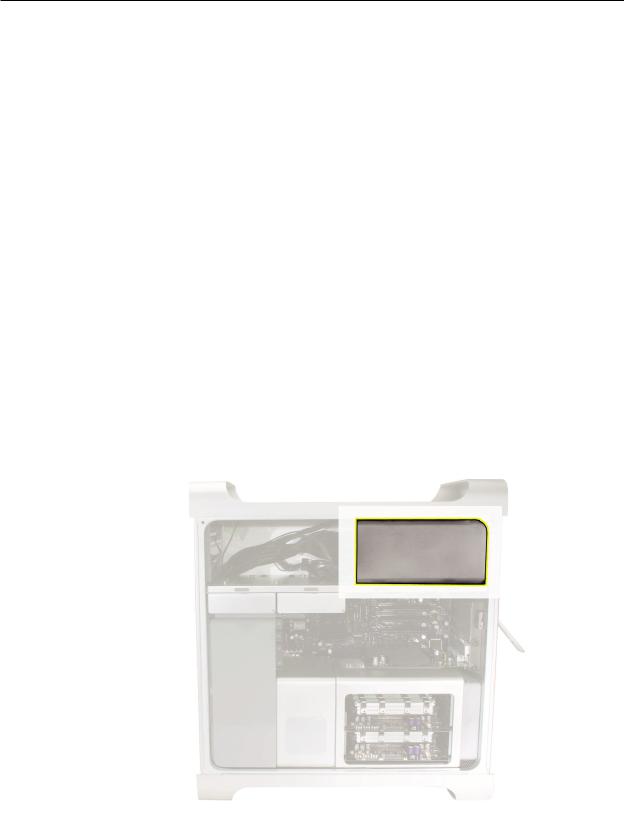
Part Location
Mac Pro Take Apart — Power Supply 29
Procedure
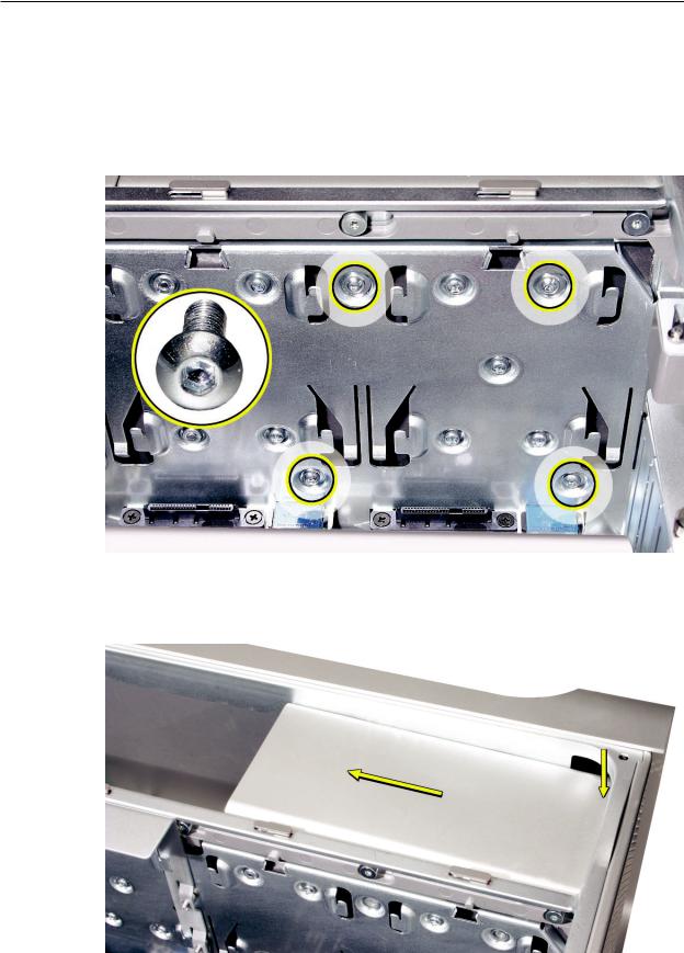
Removing the Power Supply
1.Using a magnetized 2.5 mm hex wrench remove the four power supply mounting screws from the bottom of the media shelf.
2.Depress the upper right corner of the power supply and slide the power supply toward the front of the computer.
Mac Pro Take Apart — Power Supply 30
Loading...