


 Loading...
Operation
InRow® SC
ACSC100
ACSC101

This manual is available in English on the enclosed CD.
Dieses Handbuch ist in Deutsch auf der beiliegenden CD-ROM verfügbar. Deze handleiding staat in het Nederlands op de bijgevoegde cd.
Este manual está disponible en español en el CD-ROM adjunto.
Ce manuel est disponible en français sur le CD-ROM ci-inclus.
Questo manuale è disponibile in italiano nel CD-ROM allegato.
CD-ROM
Instrukcja Obsługi w jezyku polskim jest dostepna na CD.
O manual em Português está disponível no CD-ROM em anexo.
Данное руководство на русском языке имеется на прилагаемом компакт-диске.
CD
CD .

Contents
General Information........................................................ |
1 |
Overview . . . . . . . . . . . . . . . . . . . . . . . . . . . . . . . . . . . . . . . . . . . . . . . . 1
Safety . . . . . . . . . . . . . . . . . . . . . . . . . . . . . . . . . . . . . . . . . . . . . . . . . . . 2
Commissioning ............................................................... |
3 |
Inspection Checklists . . . . . . . . . . . . . . . . . . . . . . . . . . . . . . . . . . . . . . 3
Initial inspection checklist . . . . . . . . . . . . . . . . . . . . . . . . . . . . . . 3
Electrical inspection checklist . . . . . . . . . . . . . . . . . . . . . . . . . . . 4 Mechanical inspection checklist . . . . . . . . . . . . . . . . . . . . . . . . . . 4 User interface inspection checklist . . . . . . . . . . . . . . . . . . . . . . . 5
Start-up inspection checklist . . . . . . . . . . . . . . . . . . . . . . . . . . . . 5 Final inspection checklist . . . . . . . . . . . . . . . . . . . . . . . . . . . . . . 5
Operation ......................................................................... |
6 |
Display Interface . . . . . . . . . . . . . . . . . . . . . . . . . . . . . . . . . . . . . . . . . . 6
Using the Display Interface . . . . . . . . . . . . . . . . . . . . . . . . . . . . . . . . . 7
Scrolling status screens . . . . . . . . . . . . . . . . . . . . . . . . . . . . . . . 7 Main menu screens . . . . . . . . . . . . . . . . . . . . . . . . . . . . . . . . . . .7 Navigating the main menu . . . . . . . . . . . . . . . . . . . . . . . . . . . . . . 8 Navigating the sub-menus . . . . . . . . . . . . . . . . . . . . . . . . . . . . . . 8 Using the Path statement . . . . . . . . . . . . . . . . . . . . . . . . . . . . . . . 9 Password entry . . . . . . . . . . . . . . . . . . . . . . . . . . . . . . . . . . . . . . 9 Start the cooling unit . . . . . . . . . . . . . . . . . . . . . . . . . . . . . . . . . 10 Stop the cooling unit . . . . . . . . . . . . . . . . . . . . . . . . . . . . . . . . . 10
General Configuration . . . . . . . . . . . . . . . . . . . . . . . . . . . . . . . . . . . . 11
Contacts. . . . . . . . . . . . . . . . . . . . . . . . . . . . . . . . . . . . . . . . . . . . . . . . 12
Cooling Group Configuration . . . . . . . . . . . . . . . . . . . . . . . . . . . . . . 13
Configure the cooling group . . . . . . . . . . . . . . . . . . . . . . . . . . . 13
Identify the cooling unit . . . . . . . . . . . . . . . . . . . . . . . . . . . . . . . 14
Configure Modbus . . . . . . . . . . . . . . . . . . . . . . . . . . . . . . . . . . . 14
InRow SC Operation |
i |
Control the Environment . . . . . . . . . . . . . . . . . . . . . . . . . . . . . . . . . . 15
Setpoints . . . . . . . . . . . . . . . . . . . . . . . . . . . . . . . . . . . . . . . . . .15 Run hours . . . . . . . . . . . . . . . . . . . . . . . . . . . . . . . . . . . . . . . . .16 Thresholds . . . . . . . . . . . . . . . . . . . . . . . . . . . . . . . . . . . . . . . . .16 Service intervals . . . . . . . . . . . . . . . . . . . . . . . . . . . . . . . . . . . .17
Display Settings . . . . . . . . . . . . . . . . . . . . . . . . . . . . . . . . . . . . . . . . . 18
Password & time-out . . . . . . . . . . . . . . . . . . . . . . . . . . . . . . . . .18
Override the password time-out and
require password entry immediately. . . . . . . . . . . . . . . . . . . . . .18
Date and time . . . . . . . . . . . . . . . . . . . . . . . . . . . . . . . . . . . . . . .18 Configure display . . . . . . . . . . . . . . . . . . . . . . . . . . . . . . . . . . . .19 Display units . . . . . . . . . . . . . . . . . . . . . . . . . . . . . . . . . . . . . . .19
Network Configuration. . . . . . . . . . . . . . . . . . . . . . . . . . . . . . . . . . . . 20
View Status Readings . . . . . . . . . . . . . . . . . . . . . . . . . . . . . . . . . . . . 21
Scrolling status screens . . . . . . . . . . . . . . . . . . . . . . . . . . . . . . .21 Cooling unit status . . . . . . . . . . . . . . . . . . . . . . . . . . . . . . . . . . .21 Cooling group status . . . . . . . . . . . . . . . . . . . . . . . . . . . . . . . . .22 About the cooling unit . . . . . . . . . . . . . . . . . . . . . . . . . . . . . . . .22
Event Log . . . . . . . . . . . . . . . . . . . . . . . . . . . . . . . . . . . . . . . . . . . . . . 23 Respond to Alarms. . . . . . . . . . . . . . . . . . . . . . . . . . . . . . . . . . . . . . . 23
View alarms . . . . . . . . . . . . . . . . . . . . . . . . . . . . . . . . . . . . . . . . |
23 |
Clear active alarms . . . . . . . . . . . . . . . . . . . . . . . . . . . . . . . . . . . |
23 |
Alarm messages and suggested actions . . . . . . . . . . . . . . . . . . |
24 |
Network Management Card .......................................... |
27 |
Quick Configuration . . . . . . . . . . . . . . . . . . . . . . . . . . . . . . . . . . . . . . 27
Overview . . . . . . . . . . . . . . . . . . . . . . . . . . . . . . . . . . . . . . . . . .27 TCP/IP configuration methods . . . . . . . . . . . . . . . . . . . . . . . . . .27
APC Device IP Configuration Wizard . . . . . . . . . . . . . . . . . . . . .28
.ini file utility . . . . . . . . . . . . . . . . . . . . . . . . . . . . . . . . . . . . . . .28 BOOTP & DHCP configuration . . . . . . . . . . . . . . . . . . . . . . . . . .28
Local access to the control console . . . . . . . . . . . . . . . . . . . . . .30 Remote access to the control console . . . . . . . . . . . . . . . . . . . .30
Control console . . . . . . . . . . . . . . . . . . . . . . . . . . . . . . . . . . . . .31
ii |
InRow SC Operation |
Access a Configured Network Management Card . . . . . . . . . . . . . .32
Overview . . . . . . . . . . . . . . . . . . . . . . . . . . . . . . . . . . . . . . . . . . 32 Web interface . . . . . . . . . . . . . . . . . . . . . . . . . . . . . . . . . . . . . . 32 Telnet and SSH . . . . . . . . . . . . . . . . . . . . . . . . . . . . . . . . . . . . . 33
Simple Network Management Protocol (SNMP) . . . . . . . . . . . . . 34
FTP/SCP . . . . . . . . . . . . . . . . . . . . . . . . . . . . . . . . . . . . . . . . . . 34 Modbus . . . . . . . . . . . . . . . . . . . . . . . . . . . . . . . . . . . . . . . . . . . 34
Recover From a Lost Password. . . . . . . . . . . . . . . . . . . . . . . . . . . . .35
Maintenance................................................................... |
36 |
Monthly Preventive Maintenance. . . . . . . . . . . . . . . . . . . . . . . . . . . . |
36 |
Quarterly Preventive Maintenance. . . . . . . . . . . . . . . . . . . . . . . . . . . |
38 |
Semi-Annual Preventive Maintenance. . . . . . . . . . . . . . . . . . . . . . . . |
39 |
Troubleshooting ............................................................ |
40 |
Warranty ......................................................................... |
42 |
InRow SC Operation |
iii |
American Power Conversion Legal Disclaimer
The information presented in this manual is not warranted by the American Power Conversion Corporation to be authoritative, error free, or complete. This publication is not meant to be a substitute for a detailed operational and site specific development plan. Therefore, American Power Conversion Corporation assumes no liability for damages, violations of codes, improper installation, system failures, or any other problems that could arise based on the use of this Publication.
The information contained in this Publication is provided as is and has been prepared solely for the purpose of evaluating data center design and construction. This Publication has been compiled in good faith by American Power Conversion Corporation. However, no representation is made or warranty given, either express or implied, as to the completeness or accuracy of the information this Publication contains.
IN NO EVENT SHALL AMERICAN POWER CONVERSION CORPORATION BE LIABLE FOR ANY DIRECT, INDIRECT, CONSEQUENTIAL, PUNITIVE, SPECIAL, OR INCIDENTAL DAMAGES (INCLUDING, WITHOUT LIMITATION, DAMAGES FOR LOSS OF BUSINESS, CONTRACT, REVENUE, DATA, INFORMATION, OR BUSINESS INTERRUPTION) RESULTING FROM, ARISING OUT, OR IN CONNECTION WITH THE USE OF, OR INABILITY TO USE THIS PUBLICATION OR THE CONTENT, EVEN IF AMERICAN POWER CONVERSION CORPORATION HAS BEEN EXPRESSLY ADVISED OF THE POSSIBILITY OF SUCH DAMAGES. AMERICAN POWER CONVERSION CORPORATION RESERVES THE RIGHT TO MAKE CHANGES OR UPDATES WITH RESPECT TO OR IN THE CONTENT OF THE PUBLICATION OR THE FORMAT THEREOF AT ANY TIME WITHOUT NOTICE.
Copyright, intellectual, and all other proprietary rights in the content (including but not limited to software, audio, video, text, and photographs) rests with American Power Conversion Corporation or its licensors. All rights in the content not expressly granted herein are reserved. No rights of any kind are licensed or assigned or shall otherwise pass to persons accessing this information.
iv |
InRow SC Operation |
General Information
Overview
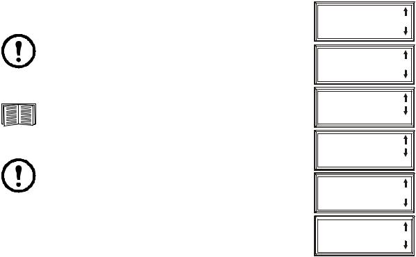
Note the definitions for the icons here and be observant for them throughout this manual. They are intended to call attention to potential hazards and important information.
Symbols used in this manual
Electrical Hazard: Indicates an electrical hazard which, if not avoided, could result in injury or death.
Danger: Indicates a hazard which, if not avoided, could result in severe personal injury or death.
Warning: Indicates a hazard which, if not avoided, could result in personal injury or damage to product or other property.
Heavy: Indicates a heavy load that should not be lifted without assistance.
Caution: Indicates a potential hazard which, if not avoided, could result in damage to the equipment or other property.
Tip Hazard: This equipment is easily tipped. Use extreme caution when unpacking or moving.
Note: Indicates important information.
Indicates that more information is available on the same subject.
Cross-reference symbol used in this manual
See another section of this document or another document for more information on this subject.
InRow SC Operation |
1 |

Safety
Read and adhere to the following important safety considerations when working with this cooling unit.
Note: All work must be performed by American Power Conversion (APC®) authorized personnel only.
Caution: Keep your hands, clothing, and jewelry away from moving parts. Check the equipment for foreign objects before closing the doors and starting the equipment.
Heavy: The equipment is heavy. For safety purposes, at least two people must be present when moving this equipment.
Tip Hazard: This equipment has a high center-of-gravity. Use extreme caution when moving.
Electrical Hazard: Do not wear jewelry when working near energized components.
Warning: Before performing any service, properly de-energize and remove access to the equipment (Lockout). Physically label the equipment as intentionally out of service (Tagout).
2 |
InRow SC Operation |
Commissioning
Warning: APC authorized personnel must perform the following procedures.
Electrical Hazard: Perform Lockout/Tagout procedures on the cooling unit before servicing the cooling unit. Failure to remove power before servicing this equipment could result in serious injury or death.
After installation is complete, verify that all components are working properly and that the cooling unit is ready to begin operation.
Inspection Checklists
Initial inspection checklist
The initial inspection ensures that the cooling unit has been properly installed, the location of the cooling unit has been properly prepared, and the cooling unit is free of damage.
Warning: The cooling unit operates under pressure. Take proper safety precautions when connecting gauges or servicing piping.
Warning: Do not operate the cooling unit with any cover, guard, door, or panel removed unless the instructions indicate otherwise. Then, proceed with extreme caution. Warning: Do not run service utilities in front of the fan outlets.
Caution: The vapor barrier minimizes moisture infiltration. Without a vapor barrier, it will be difficult to maintain the humidity in the room.
Caution: Do not introduce unconditioned outside air into the space.
Note: A minimum of 900 mm (36 in) of clear floor space in front of and behind the cooling unit is required for service access. To roll the cooling unit out of the row, there must be a minimum of 1200 mm (48 in) of clear floor space in front of or behind the cooling unit. Out-of-row service requires 760 mm (30 in) of side clearance in addition to the front and rear clearance.
Ensure that:
The installation procedure is complete according to the installation manual.
The walls, floor, and ceiling of the room where the cooling unit is located are sealed with a vapor barrier.
There is no evidence of damage to the cooling unit.
The cooling unit is level and joined to the adjacent racks or secured to the floor.
The clearance around the cooling unit is in accordance with local and national codes and regulations as well as the installation manual.
InRow SC Operation |
3 |
Electrical inspection checklist
The electrical inspection verifies that all electrical connections are secure and correct and that the cooling unit is properly grounded.
Electrical Hazard: All electrical wiring must comply with local and national codes and regulations.
Electrical Hazard: The equipment must be grounded (do not use a water-pipe ground).
Ensure that the:
Incoming voltages match the phase and voltage listed on the nameplate.
Electrical wiring complies with local and national codes and regulations.
Cooling unit is properly grounded.
Electrical connections are tight, including contactors, terminal blocks, controllers, switches, relays, auxiliary devices, and field connections.
Mechanical inspection checklist
The mechanical inspection verifies that all mechanical components and connections are secure and tight and ready for start-up and system charging. The inspection ensures that field piping is properly installed to promote oil return to the compressor.
Caution: Improperly installed piping may result in improper operation and possible damage to the cooling unit or surrounding equipment.
Ensure that the:
Fans are turning freely and that the blades are not distorted or bent.
Condensate drain line is at least the size of the drain connection.
Mechanical connections are tight, including compressor and receiver connections.
Ceiling tile adapter is secured to the building structure with properly-sized safety wire.
Covers and guards are in place.
4 |
InRow SC Operation |
User interface inspection checklist
The user interface inspection verifies that the sensors and internal communications links of the cooling unit are installed properly.
Ensure that:
An A-Link bus is connected to each cooling unit in the group and a terminator is plugged into all unused A-Link connectors.
The input contacts and output relays are connected correctly.
The building management system (if used) is connected correctly.
The temperature sensor is properly routed and mounted on the front (entering air side) of the enclosure immediately to the left or right of the equipment (if InRow or RACS operating mode will be selected).
The network port is connected correctly and an IP address has been assigned to the equipment.
Start-up inspection checklist
The start-up inspection ensures that the cooling unit is operating properly after the initial start-up. This inspection verifies that all modes of operation are working correctly and that the cooling unit is ready for normal operation.
While the cooling unit is operating, ensure that the:
Cooling unit is free from malfunctions, unusual vibrations, or other irregularities in each mode of operation.
Cool cycles engage.
Cooling configuration matches the application of the cooling unit.
Air filters are clean and free of debris. Replace air filters with APC part number 875-2013.
Clogged filter alarm is operating properly:
Cover 1/3 of the filter area and monitor alarm performance.
Compressor suction and discharge pressures are recorded.
Final inspection checklist
The final inspection verifies that the system is clean and the start-up form has been sent to APC.
Ensure that:
The interior and exterior of the cooling unit is clean and free from debris.
Packaging materials have been disposed of properly.
The Start-up form was completed and sent to APC.
InRow SC Operation |
5 |
Operation
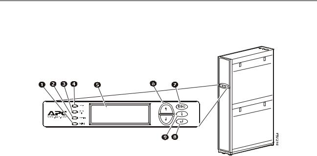
Display Interface
Item |
|
Function |
|
|
|
|
Critical Alarm LED (red) |
When illuminated, a critical alarm condition exists that requires your |
|
|
immediate attention. |
|
|
|
|
Warning Alarm LED (yellow) |
When illuminated, a warning alarm condition exists. Failure to correct this |
|
|
condition could cause a critical alarm. |
|
|
|
|
Check Log LED (yellow) |
When illuminated, at least one new event has been logged since the last |
|
|
time the log was checked. Only events that pertain to the operation of the |
|
|
cooling unit will activate this LED. |
|
|
|
|
Status LED (green) |
When illuminated, the cooling unit is receiving electrical power. When the |
|
|
LED is flashing, the cooling unit is downloading firmware for the |
|
|
controller. This may take a few minutes. |
|
|
|
|
Liquid Crystal Display (LCD) |
View alarms, status data, context-sensitive help, and modify configurable |
|
|
items. |
|
|
|
|
Up and down arrow keys |
Select menu items and access information. |
|
|
|
|
ESC key |
Return to previous screen or cancel current operation. |
|
|
|
|
Enter key |
Open menu items and input changes to the cooling unit settings. |
|
|
|
|
Help key |
Display context-sensitive help. Press the help key for information about |
|
|
each option on the screen and for instructions on performing the tasks. |
6 |
InRow SC Operation |
Using the Display Interface
Every time you apply power to the cooling unit, the display interface initializes, causing the LEDs to cycle and the alarm tone to activate.
Scrolling status screens
After start-up, the interface displays the firmware revision number of the display interface. The display interface then scrolls automatically and continuously through screens of status information.
Status Screen Name |
Status Information Displayed |
|
|
APC InRow SC Status |
• On/Standby |
|
• Cooling unit name |
|
• Cooling unit location |
|
|
Group |
• Alarms/No Alarms |
|
• Cool Output kW |
|
• Cool Setpoint °C (or °F) |
|
• Max Rack (Maximum Rack Temperature) °C (or °F) |
|
|
Unit |
• Alarms/No Alarms |
|
• Cool Output kW |
|
• Air Flow CFM (cubic feet per minute) or L/s (liters per second) |
|
• Rack Inlet °C (or °F) |
|
|
Press the up or down arrow key to interrupt the automatic scrolling and view a specific status screen. Screens automatically begin to scroll after five seconds of inactivity. Press the ENTER or ESC key to return to the main menu screen.
Main menu screens
On any top-level status screen, press the ENTER or ESC key to open the main menu screen.
Note: If the display interface is inactive for the time configured for the password time-out, it returns to the scrolling status screens.
For information on setting the password time-out, see page 18.
Note: Pressing the up arrow key from the top line of the top screen of the main menu will take you to the top line of the bottom screen.
Clear Event Log
Configure Modbus
 Set Date & Time
Set Password
Set Display Units
Configure Display
Configure Network
About InRow SC
Set Identification
Service Intervals
View Run Hours
Configure Unit
Configure Group
Set Group Setpoints
Set Unit Threshlds
View Group Status
View Unit Status
na1636f
InRow SC Operation |
7 |
Navigating the main menu
Selector arrows. Press the up or down arrow key to move the selector arrow to a menu option or setting. Press the ENTER key to view the selected screen or modify the setting.
Continue arrows. Continue arrows indicate that additional options or settings are available on a menu or status screen. Press the up or down arrow key to view the additional items.
Navigating the sub-menus
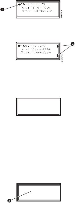
Selecting a main menu option displays the sub-menu screen for that option. Use the up or down arrow key to move the selector arrow to the setting that you wish to change, and press the ENTER key.

 Time: 13:15:23 Date: 29-Jan-09 Format: dd-mmm-yy

 na1623e
•List of choices. If the setting is a list of choices, an input arrow is displayed next to the setting. Press the up or down arrow key to select the choice you want, and then press the ENTER key to exit the input mode and save the setting. Press the ESC key to exit without saving.
•Numbers or text fields. If the setting is a number or text field, use the arrow keys to select the value of the first character, and press the ENTER key to move to the next. Press the ENTER key after the last character is set to exit the input mode and save the setting. Press the ESC key to exit without saving. If an invalid value is entered, the display beeps and restores the previous valid value to the field.
•Input arrows next to a selected setting indicate that the setting can be modified by pressing the up or down arrow key. Press the ENTER key to save the change or the ESC key to cancel the change.
Time: 13:15:23 Date:  29-Jan-09 Format: dd-mmm-yy

 na1622b
8 |
InRow SC Operation |
Using the Path statement
Select the mainand sub-menu options specified in the path statement to view or configure a setting. The path statement lists the mainand sub-menu items you select to navigate to the item to view or modify. The parts of the path statement are defined below:
Path: Main > Set Password >Change Passwords
Main > Your starting point is the main menu.
Set Password > Scroll to and select this option from the main menu.
Change Passwords > Scroll to and select this option from the sub-menu.
Subsequent options are listed and defined under the path statement.
Password entry
Path: Main Menu > Set Password > Change Passwords
The cooling unit has two levels of password protection:
•Device password for users who need to change basic and environmental settings.
•Admin password for users who need to modify settings that control the components in the cooling unit or change advanced options.
When you try to change any of the settings, the local display prompts you to enter your Admin password. The default value for both the Device and Admin passwords is apc (lower case). To enter your password, use the up or down arrow keys to scroll through the available character set. Press the ENTER key to select the current letter and move the cursor to the next letter position. After selecting the last letter of your password, press the ENTER key once more to submit your password. If the Device and Admin passwords have been configured to be unique, the Admin password can be entered for the Device password, and Admin privileges will be granted.
Once the password is entered, it remains in effect until the period of inactivity exceeds the Password Time-out setting.
See “Password & time-out” on page 18.
Note: Passwords are case-sensitive.
InRow SC Operation |
9 |
Start the cooling unit
Path: Main Menu > On/Standby
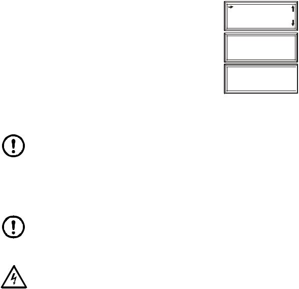
Limiting access by requiring a password: Selecting On/ Standby will display the Operate: On/Standby screen. The second line on the screen is Limit Access: Yes/No. Select Yes to require a password in order to stop or start the unit. When the curser is on Operate: On/Standby and the ENTER key is pressed, the screen will display Enter Password. The password must then be entered in order to continue. If Limit Access: No is selected, a password is not required.
To start the cooling unit, change the setting to On by pressing the ENTER key to toggle from Standby to On. At that point, the fans will start or Unit startup in progress will appear if the Start-Up Delay option is set to restart multiple cooling units sequentially.
The cooling unit will run according to the configured settings.
 Operate: On/Standby
Limit Access: Yes
Enter Password
********************

 na2969a
Note: On/Standby only affects the local cooling unit. You must set the On/Standby option for each cooling unit in the cooling group.
Note: To toggle between On and Standby from the scrolling status screens, press the ENTER key three times in rapid succession. This operation can only be done if Limit Access: Yes/No is set to No.
Stop the cooling unit
Path: Main Menu > On/Standby
Note: The Limit Access: Yes/No information provided above is also applicable for shutting down the unit.
Press the ENTER key to change the setting to Standby. The cooling unit will enter the standby mode
Electrical Hazard: The Standby option does not remove power from the cooling unit. You must disconnect power at the mains to remove power from the cooling unit.
10 |
InRow SC Operation |
Loading...