


 Loading...
Installation and
Configuration
Dry Contact I/O
SmartSlot Card
AP9613

This manual is available in English on the enclosed CD.

Contents
Safety Overview 1
Important Safety Information . . . . . . . . . . . . . . . . . . . . . . . . . . . . 1
Product Overview 2
Introduction. . . . . . . . . . . . . . . . . . . . . . . . . . . . . . . . . . . . . . . . . . . 2
Product description 2
Hardware and software requirements and tools needed 3
Showing the product detail . . . . . . . . . . . . . . . . . . . . . . . . . . . . . . 4
Itemizing the features of the Dry Contact I/O SmartSlot Card 4 Itemizing the input contact and output relay terminal blocks 6
Configuring the Dip Switches 7
Location of dip switches . . . . . . . . . . . . . . . . . . . . . . . . . . . . . . . . 7
Dip switches: input and outputs. . . . . . . . . . . . . . . . . . . . . . . . . . 8
Installing 9
Planning your installation . . . . . . . . . . . . . . . . . . . . . . . . . . . . . . . 9
Operating considerations 9 Connection strategies 11
Installation steps . . . . . . . . . . . . . . . . . . . . . . . . . . . . . . . . . . . . . 12
Connecting to the configuration utility . . . . . . . . . . . . . . . . . . . 14
Specifications 16
Electrical, physical, environmental, and approval specifications 16
Ratings for input contacts and output relays 17
Warranty 18
Two-Year Factory Warranty. . . . . . . . . . . . . . . . . . . . . . . . . . . . . 18
Terms of warranty 18 Non-transferable warranty 18 Exclusions 18
Warranty claims 19
Dry Contact I/O SmartSlot Card |
i |
Disclaimer 20
APC Worldwide Customer Support 32
ii |
Dry Contact I/O SmartSlot Card |
Safety Overview
Important Safety Information
Follow all applicable electrical codes for your installation area.
Read the instructions carefully to become familiar with the equipment before trying to install, operate, service or maintain it. The following special messages may appear throughout this manual or on the equipment to warn of potential hazards or to call attention to information that clarifies or simplifies a procedure.
The addition of this symbol to a Danger or Warning safety label indicates that an electrical hazard exists which will result in personal injury if the instructions are not followed.
This is the safety alert symbol. It is used to alert you to potential personal injury hazards. Obey all safety messages that follow this symbol to avoid possible injury or death.
 DANGER
DANGER indicates an imminently hazardous situation which, if not avoided, will result in death or serious injury.
 WARNING
WARNING indicates a potentially hazardous situation which, if not avoided, can result in death or serious injury.
 CAUTION
CAUTION indicates a potentially hazardous situation which, if not avoided, can result in minor or moderate injury.
NOTICE
NOTICE addresses practices not related to physical injury including certain environmental hazards, potential damage or loss of data.
Dry Contact I/O SmartSlot Card |
1 |

Product Overview
Introduction
The Schneider Electric™ Dry Contact I/O SmartSlot Card (AP9613) is a management product that provides the following features:
•UPS status information presented through 6 fully isolated output relays. This is expandable to 8 using universal input/output ports and optional Dry Contact I/O Accessory (AP9810)
•UPS control and testing by using 4 opto-isolated input contacts. An additional 4 input contacts (non opto-isolated) may be added using universal input/output ports and an optional Dry Contact I/O Accessory (AP9810)
•UPS control and testing based on environmental conditions using universal input/output ports and an optional Environmental Sensor (AP9335T or AP9335TH)
•screw terminal connectors for easy integration into various management systems
•a Configuration Utility user interface to customize your setup, see “Connecting to the configuration utility” on page 14
For more details, see “Showing the product detail” on page 4, “Configuring the Dip Switches” on page 7, “Installing” on page 9, “Specifications” on page 16.
Product description
The Schneider Electric Dry Contact I/O SmartSlot Card consists of a printed circuit board assembly. It installs in the SmartSlot of the UPS host device. The product contents are:
•the Dry Contact I/O SmartSlot Card
•the USB A to Mini B cable (to access the Configuration Utility, see “Connecting to the configuration utility” )
•this printed manual
2 |
Dry Contact I/O SmartSlot Card |
Hardware and software requirements and tools needed
The Dry Contact I/O SmartSlot Card works with most APC by Schneider Electric UPS devices with an output rated less than or equal to 160kVA and an available SmartSlot.
While most devices meet this requirement; verify the compatibility of your device by locating it on the APC website, www.apc.com, and checking for compatible accessories.
You need the following tools:
•#1 Phillips screwdriver for screw terminals
•#2 Phillips screwdriver for SmartSlot screws
•a wrench of size 1" or 25.4 mm, or adjustable, to tighten the grommet
For the Configuration Utility, you need: Windows (XP, 2003, 2008, Vista, or 7) and Internet Explorer browser v7 or higher.
Dry Contact I/O SmartSlot Card |
3 |
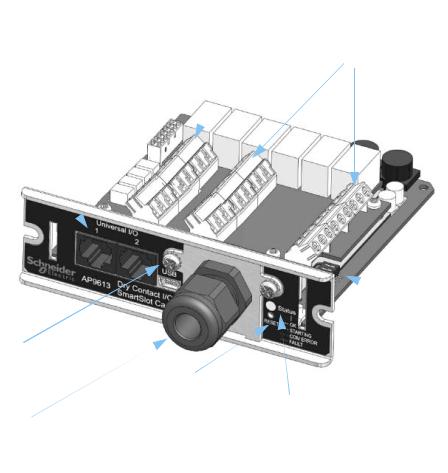
Showing the product detail
Itemizing the features of the Dry Contact I/O SmartSlot Card

4 |
Dry Contact I/O SmartSlot Card |
Item |
Name |
Description |
Universal I/O |
These support the AP9335T/ TH and AP9810 dry |
|
ports 1 and 2 |
contact accessories |
|
USB cable |
Connecting this to your PC enables usage of the |
|
connector |
Configuration Utility. |
|
Reset button |
Use an appropriately sized, non-metallic tool to |
|
|
press the Reset button. |
|
|
Holding the button for 5 seconds reboots the Card. |
|
|
Holding the button for 25 seconds resets the Card to |
|
|
the factory defaults. (The status light flashes green |
|
|
when you do this). |
|
Status indicator |
• |
SOLID GREEN indicates communications and |
|
• |
operations are fine |
|
FLASHING GREEN indicates the Card is |
|
|
• |
initializing |
|
FLASHING RED indicates a communication fault |
|
|
• |
SOLID RED indicates a non-operational fault |
Dip switches |
These are located near the back of the front panel on |
|
|
the right-hand side. See the “Location of dip |
|
switches” and “Configuring the Dip Switches” sections.
|
Output relay |
Connections for alarm outputs. |
|
terminals |
See “Itemizing the input contact and output relay |
|
|
terminal blocks” and “Ratings for input contacts and |
|
|
output relays” . |
|
Input contact |
Connections for control inputs. |
|
terminals |
See “Itemizing the input contact and output relay |
|
|
terminal blocks” and “Ratings for input contacts and |
|
|
output relays” . |
|
Cord grip |
Supports the cabling that is used to control external |
|
|
devices, or to connect up external switches. The |
|
|
bare wires connect to the terminal blocks on the |
|
|
Card. |
|
|
The cord grip is plastic and can secure a single cord |
|
|
with a diameter range of 5.8 – 10mm. This limits the |
|
|
number of conductors (inside the cord) and the |
|
|
power ratings. |
Dry Contact I/O SmartSlot Card |
5 |

Itemizing the input contact and output relay terminal blocks
Number of positions on each terminal block |
9 |
Tightening torque |
0.35 N.m |
Tightening torque max |
0.4 N.m |
Wire stripping length |
5 mm |
Minimum wire gauge |
0.14 mm2 (26 AWG) |
Maximum wire gauge |
2.5 mm2 (14 AWG) |
6 |
Dry Contact I/O SmartSlot Card |
Loading...