


APC KVM Switch
AP9268
AP9278
For use in the United States: English
Thank You!
Thank you for selecting the APC KVM Switch. The APC KVM Switch has been designed for many years of reliable, maintenance free service. APC is dedicated to the development of high-performance electrical power conversion and control products and we hope that you will find this product a valuable, convenient addition to your computing system.
Please read this manual! It provides important safety, installation and operating instructions that will help you get the most from your switch.
Save this manual! It includes instructions for obtaining factory service should the proper operation of the APC KVM Switch come into question.
Radio Frequency Interference
WARNING: Changes or modifications to this unit not expressly approved by the party responsible for compliance could void the user’s authority to operate this equipment.
FCC Statement
NOTE: This equipment has been tested and found to comply with the limits for a Class A digital device, pursuant to Part 15 of the FCC Rules. These limits are designed to provide reasonable protection against harmful interference when the equipment is operated in a commercial environment. This equipment generates, uses and can radiate radio frequency energy and, if not installed and used in accordance with the instruction manual, may cause harmful interference to radio communications. Operation of this equipment in a residential area is likely to cause harmful interference in which case
the user will be required to correct the interference at his own expense.
Canadian Department of Communications Statement
This digital apparatus does not exceed the Class A limits for radio noise emissions from digital apparatus set out in the Radio Interference Regulations of the Canadian Department of Communications.
Le présent appareil numérique n'émet pas de bruits radioélectriques les limites applicables aux appareils numériques de la class A prescrites dans le Règlement sur le brouillage radioélectrique édicté par le Ministère des Communications du Canada.

Rack Mount Safety Considerations
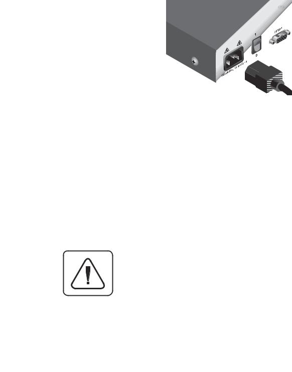
Note: The AC inlet is the main disconnect.
•Elevated Ambient Temperature: If installed in a closed rack assembly, the operation temperature of the rack environment may be greater than room ambient. Use care not to exceed the rated maximum ambient temperature of the unit.
•Reduced Air Flow: Installation of the equipment in a rack should be such that the amount of air flow required for safe operation of the equipment is not compromised.
•Mechanical Loading: Mounting of the equipment in the rack should be such that a hazardous condition is not achieved due to uneven mechanical loading.
•Circuit Overloading: Consideration should be given to the connection of the equipment to the supply circuit and the effect that overloading of circuits might have on overcurrent protection and supply wiring. Consider equipment nameplate ratings for maximum current.
•Reliable Earthing: Reliable earthing of rack mounted equipment should be maintained. Pay particular attention to supply connections other than direct connections to the branch circuit (e.g. use of power strips).

APC KVM Switch Installer/User Guide
INSTRUCTIONS: The exclamation point within an equilateral triangle is intended to alert the user to the presence of important operating and maintenance (servicing) instructions in the literature accompanying the appliance.
DANGEROUS VOLTAGE: The lightning flash with arrowhead symbol, within an equilateral triangle, is intended to alert the user to the presence of uninsulated “dangerous voltage” within the product's enclosure that may be of sufficient magnitude to constitute a risk of electric shock to persons.
PROTECTIVE GROUNDINGTERMINAL: Aterminalwhichmust be connected to earth ground prior to making any other connections to the equipment.
POWER ON: This symbol indicates the principal on/off switch is in the on position.
POWER OFF: This symbol indicates the principal on/off switch is in the off position.

Table of Contents |
|
|
Chapter 1 - Product Overview |
|
|
1.1 Feature Overview .......................................................................................................... |
1 |
|
1.2 Compatibility........................................................................................................................... |
3 |
|
Chapter 2 - Installation |
|
|
2.1 |
Basic Install ....................................................................................................................... |
4 |
2.2 Advanced Install ............................................................................................................ |
9 |
|
Chapter 3 - Basic Operations |
|
|
3.1 |
Overview........................................................................................................................ |
10 |
3.2 Keyboard Control ........................................................................................................ |
11 |
|
3.3 |
Keyboard Switching .......................................................................................................... |
12 |
3.4 |
System Control and Maintenance ............................................................................... |
13 |
Chapter 4 - On-Screen Display Operations |
|
|
4.1 |
Activating OSD ............................................................................................................ |
14 |
4.2 The OSD Window...................................................................................................... |
15 |
|
4.3 The Command Menu ............................................................................................... |
16 |
|
4.4 Basic Channel Maintenance .................................................................................. |
17 |
|
4.5 The ID Window .......................................................................................................... |
19 |
|
4.6 Administrator Functions .......................................................................................... |
21 |
|
Chapter 5 - Advanced Operation |
|
|
5.1 Multiuser Operations......................................................................................................... |
24 |
|
5.2 |
Multi Chassis Operation.................................................................................................. |
25 |
5.3 |
Keyboard Translation ........................................................................................................ |
27 |
Chapter 6 - Channel Scanning |
|
|
6.1 Choosing a Scanning Method .............................................................................. |
29 |
|
6.2 Turning Scanning On and Off .............................................................................. |
30 |
|
6.3 |
Scanning by List .................................................................................................................. |
31 |
Chapter 7 - Appendices |
|
|
7.1 Specifications: APC KVM Switch ............................................................................ |
32 |
|
7.2 Specifications for Remote User Receiver ............................................................ |
33 |
|
7.3 FLASH Upgrading ...................................................................................................... |
34 |
|
7.4 Troubleshooting ................................................................................................................. |
36 |
|
7.5 If Problems Persist ............................................................................................................... |
41 |
|
Entire contents copyright 2001 American Power Corporation.
All rights reserved; reproduction in whole or in part without permission is prohibited.

Product Overview
1.1 Product Overview - Feature Overview
The APC KVM Switch allows you to control up to 64 PC, Sun or USB computers with one keyboard, monitor and mouse. The APC KVM Switch works with Sun Workstations, USB computers, IBM PC/AT (with adapter separately available from APC), and PS/2 systems and 100% compatible machines with support for VGA, SVGA, XGA and XGA-II video. Sun and PS/2 keyboard and mouse peripherals are supported through the rear of the unit.
Multiplatform
The APC KVM Switch adds multiplatform capabilities to your switching system by simultaneously supporting any combination of PS/2, Sun or USB computers in the same system. Switch easily across platforms with APC KVM Switch’s On-Screen Menu system.
Multiuser/Remote Access Capability
The APC KVM Switch supports two simultaneous users in the system. This second user may be placed up to 500 feet away from the Switch system. Built-in extension lets you place your second keyboard, monitor and mouse wherever you need them most. Within the base unit, APC KVM Switch performs as a complete 2 x 8 matrix switch with both users independently accessing any of the eight attached PCs at the same time.
On-screen display (OSD) capability
Configure and control your APC KVM Switch with on-screen menuing! Name your computer channels anything you wish, then select the desired computer from an easy-to-use menu. Secondary menus let you configure and initiate channel scanning and other system features.
Advanced security for total control over system access
Use the advanced multi-level security feature to configure and control server access for every type of user in the system. The administrator has full access privileges, while individual users can have viewing or viewing/editing capability for each attached server.
FLASH upgrade capability
The APC KVM Switch is FLASH upgradable. This allows you to update your firmware at any time through a simple serial connection to insure that your APC KVM Switch is always running at its best. FLASH upgrades are available for download from www.apc.com.
The APC KVM Switch offers support for numerous PS/2 mice including: IBM ScrollPoint, Logitech MouseMan Wheel, Logitech Trackman Marble Wheel, Logitech
1
APC KVM Switch Installer/User Guide
Trackman Marble FX, Kensington 4 Button Mouse, Microsoft Explorer Mouse and the Microsoft IntelliMouse family.
Plug and play
The APC KVM Switch supports Plug and Play video and is compliant with the VESA DDC2B standard.
Mouse translation
For added compatibility with your current equipment, APC KVM Switch features mouse translation capability. Operated through the APC KVM Switch, your mouse will work with any attached computerregardless of whether the computer is Sun, USB, serial or PS/2 mouse compatible!
Expansion for up to 64 computers
An APC KVM Switch unit will support from one to eight attached computers, or channels. If more than eight channels are needed, multiple units can be cascaded together for expansion. Up to two tiers of units can be connected for a total of 64 attached computers in one system.
“Keep Alive” feature
APC KVM Switch’s “Keep Alive” feature allows attached servers to power the unit in the event of an APC KVM Switch power failure. This prevents attached computers from locking up and keeps you from losing time and data.
OSD Configuration Utility
The OSD Configuration Utility allows the administrator to easily configure and download a channel list with defined users and access privileges to the entire system. This utility will also read and save your current configuration for extra security.
AutoBoot Technology
The AutoBoot feature boots all attached servers during initial power-up or after a power failure. Computers are booted transparently without operator intervention, and may be powered-up one-at-a-time or all at once. When the power stabilizes, a channel may be selected.
Built-in scanning capabilities
A built-in scanning feature allows you to automatically monitor, or scan, connected computers without intervention. When keyboard activity is detected, scanning is suspended until all activity stops. Scanning then resumes with the next channel in sequence.
2
Push-button & keyboard switching
In addition to using the on-screen menus, you can switch computer channels in one of three easy ways: via the APC KVM Switch channel push-buttons, with the Scan button or with a simple keyboard sequence.
Status indicator LEDs
Indicator LEDs give you constant readings on the status of your APC KVM Switch unit. Status, scanning and channel LEDs take the guesswork out of system operation and diagnostics.
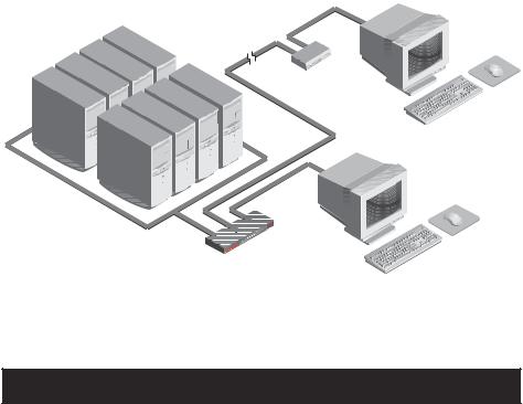
A typical APC KVM Switch configuration is shown below.
1.2 Compatibility
XGA/XGA-II support
If you wish to use XGA or XGA-II video, you will need to purchase an adapter available from your local reseller.
3
APC KVM Switch Installer/User Guide
2.1Basic Installation
1.Power down all computers that will be part of your APC KVM Switch system.
Connecting your Local Peripherals
2.Locate your keyboard, video monitor and mouse.
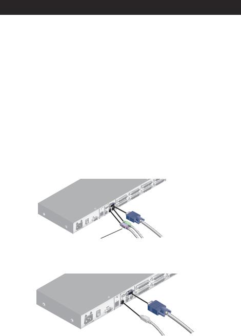
3.Plug your VGA monitor cable into the port labeled  on the back of your APC KVM Switch or plug your 13W3 monitor cable into the included adapter. Either plug your Sun connector into the port labeled “SUN” or
plug your PS/2 keyboard cable and your PS/2 mouse cable into the ports labeled  and
and  respectively.
Note: A PS/2 keyboard will not function if a Sun keyboard is attached.
However, you may use a PS/2 mouse with a Sun keyboard.
VGA MONITOR CABLE
PS/2 MOUSE CABLE
PS/2 KEYBOARD CABLE
Attaching your PS/2 keyboard and mouse
VGA MONITOR CABLE
SUN KEYBOARD CABLE
Attaching your SUN connector
4
Basic Installation
Connecting your Remote Peripherals
4.Plug a standard Category 5 Unshielded Twisted Pair cable (up to 500 feet) into the RJ-45 style modular jack on the rear of the APC KVM Switch. APC C5T or APC P5T cable is strongly recommended to achieve best performance and maximum distance. If you use a different Category 5 cable, make sure it is terminated to the EIA (TIA) 568 B standard, commonly used for 10BaseT Ethernet.
5.Route the Category 5 cable to the location where you intend to place the secondary monitor, keyboard and mouse.
6.If you are using Remote PS/2 peripherals
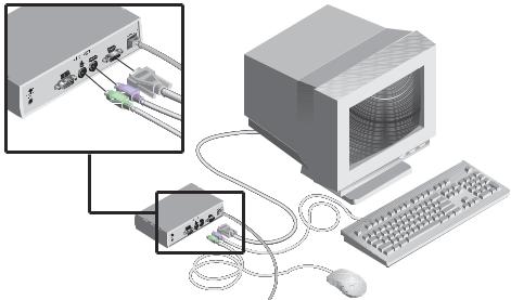
Place the Remote User Receiver near the monitor and connect your monitor, keyboard and mouse to the connectors on the rear of the Remote User Receiver (AP9279) just as you would connect them to your computer. Make sure you
connect your monitor’s power supply to appropriate electrical outlets. (Please note that the  connector on the rear of the Remote User Receiver is not
used in an APC KVM Switch configuration. Do not connect anything to the  connector on the rear of the Remote User Receiver.)
5
APC KVM Switch Installer/User Guide
7.Connect the Category 5 cable to the modular jack on the rear of the Remote User Receiver.
8.Connect the circular power plug from the wall mount power supply to the power port on the Remote User Receiver. Then plug the power supply into a convenient electrical outlet. Verify that the Remote User Receiver’s POWER light is now lit.
Cable |
Description |
Length |
|
|
|
|
|
AP9850 |
PS/2 VGA cable |
10 ft. |
|
AP9851 |
PS/2 VGA cable |
25 ft. |
|
|
|
|
|
AP9855 |
USB VGA cable |
12 ft. |
|
|
|
|
|
AP9854 |
SUN 13W3 cable |
15 ft. |
|
|
|
|
|
AP9853 |
SUN VGA cable |
15 ft. |
|
|
|
|
|
6
Basic Installation
Connecting Computers to the APC KVM Switch
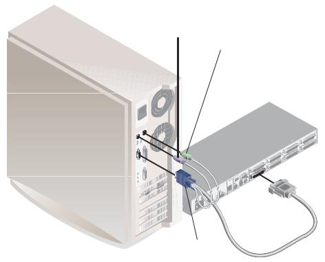
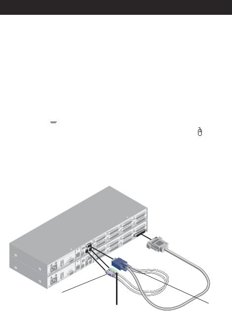
9.Locate the input cable appropriate to the computer you are connecting. (APC KVM Switch cable types are identified on page 6.) Plug this cable into any numbered channel port on the rear of theAPC KVM Switch. The other end of the input cable will have up to three connectors depending on type. The PS/2 mouse connector is designated by a mouse icon.
Use only the keyboard and mouse connectors that are appropriate for your machine, and leave the others unconnected.
Plug these connectors into the matching ports on your computer.
PS/2 KEYBOARD CABLE
PS/2 MOUSE CABLE
VGA MONITOR CABLE
AP9850 CABLE SHOWN
10.Locate your next input cable. Repeat step 10 until all computers are properly attached to the APC KVM Switch.
7
APC KVM Switch Installer/User Guide
11.Locate the proper power cord and plug it into the IEC power connector on the APC KVM Switch. Make sure that the power switch is off, then plug the other end of the power cord into an appropriate AC wall outlet. This outlet must be near the equipment and easily accessible to allow for unplugging prior to any servicing of the unit.
12.Power-up your APC KVM Switch unit first, then power up all attached computers.
13.If your remote user location utilizes Sun peripherals you will need to set the APC KVM Switch to recognize them before they can be used. To do this:
a.Activate the on-screen display (OSD) by pressing either of the keyboard Control keys twice within one second.
b.Press the Control keys twice more to access Administrator Commands.
c.Use your arrow keys to highlight “Administrator Functions” and press Enter.
d.Highlight and select the “Remote User” menu selection. Use the space bar to cycle through peripheral types and select the ones appropriate to your system. Press Enter to select.
The APC KVM Switch and all attached computers should be powereddown before servicing the unit. Always disconnect the power cord from the wall outlet.
8
Basic Installation
2.2 Advanced Install
Attaching Multiple Switch Units
(Please note that cascading can only be done with AP9850, AP9851 or AP9853 cables)
1.Follow steps 1-8 of the Basic Install section for each cascaded unit.
2.Plug the 25-pin “D” connector of your input cable into any available channel port on the rear of your base Switch unit.
3.Plug the 15-pin video connector on the other end of the cable into the
port labeled 


 on your first cascading Switch unit. Plug the PS/2 mouse connector, designated by a yellow band or mouse icon, into the port. Plug the remaining 6-pin miniDIN keyboard connector into the
  port.
port.
4. Follow steps 9-11 for each attached computer.
CASCADING
UNIT
BASE UNIT
PS/2 KEYBOARD CABLE
PS/2 MOUSE CABLE
5.Repeat steps 2-3 for every cascaded Switch unit in your system.
6.Power-up your Switch unit(s) first, then all attached computers.
VGA MONITOR CABLE
9

APC KVM Switch Installer/User Guide
3.1 Basic OperationsOverview
Your APC KVM Switch may be operated in a non-secure (no password required) or secure (password required) mode. All units ship defaulted to the non-secure mode.Forinformationonimplementingpasswordsecurity,seethe“Administrator Functions” section of chapter 4.
Computers may be powered-up one-at-a-time or all at once. No operator intervention is required during booting. As the system stabilizes, the green LED over each channel will light, indicating that the attached computer is powered on. A computer may now be selected via the on-screen display menu or, if you are in non-secure mode, channel push-buttons, the Scan button or keyboard hot-key sequence. The amber LED will light at the active computer.
The Scan push-button has one LED over it. Press the button momentarily to switch to the next computer in sequence. The LED will turn amber briefly during the channel switch. Press and hold the button for one second to initiate channel scanning. The LED will turn green while you are in scan mode.
There is one status LED. The LED lights red if an internal failure occurs. The LED will blink green for several seconds during power-up while the system performs a self-diagnostic. After initialization, the LED remains green during normal operation and blinks only when you are in Command Mode.
10
 Loading...