


MasterSwitch
Power Distribution Unit
AP9211
AP9212
AP9217
AP9218
User’s Guide

 MasterSwitch Power Distribution Unit
Contents
Introduction . . . . . . . . . . . . . . . . . . . . . . . . . . . . . . . . . 1
Product Description . . . . . . . . . . . . . . . . . . . . . . . . . . . . . 1
Front panel 1
LEDs 2
Rear panel 3
Initial Setup . . . . . . . . . . . . . . . . . . . . . . . . . . . . . . . . . . . 4
Configuring TCP/IP settings 4
Customizing your configuration 4
Auto-configuration 4
Managing the MasterSwitch PDU. . . . . . . . . . . . . . . . . . 5
Management Interfaces . . . . . . . . . . . . . . . . . . . . . . . . . . 5
Management Options 5
Web interface 5
Control Console interface 6
WAP Interface 8
Password-Protected Accounts . . . . . . . . . . . . . . . . . . . . . . 9
Menu Items . . . . . . . . . . . . . . . . . . . . . . . . . . . . . . . . . 10
Introduction . . . . . . . . . . . . . . . . . . . . . . . . . . . . . . . . . 10
Outlets . . . . . . . . . . . . . . . . . . . . . . . . . . . . . . . . . . . . . . 11
MasterSwitch . . . . . . . . . . . . . . . . . . . . . . . . . . . . . . . . . 12
Event Log. . . . . . . . . . . . . . . . . . . . . . . . . . . . . . . . . . . . 13
Retrieving the Event Log by using FTP 13 |
|
||
Using a spreadsheet to view the Event Log |
14 |
||
Deleting the Event Log in the FTP interface |
14 |
||
Network . . . . . . |
. . . . |
. . . . . . . . . . . . . . . . . . . . . . |
. . . . . 15 |
TFTP/FTP |
15 |
|
|
Telnet/Web |
16 |
|
|
SNMP |
16 |
|
|
System . . . . . . . |
. . . . |
. . . . . . . . . . . . . . . . . . . . . . |
. . . . . 18 |
Outlet User Management 20 |
|
||
Identification |
21 |
|
|
Date/Time |
21 |
|
|
File Transfer |
22 |
|
|
Links |
23 |
|
|
MasterSwitch Power Distribution Unit User’s Guide |
ii |

Contents
Help . . . . . . . . . . . . . . . . . . . . . . . . . . . . . . . . . . . . . . . . 24
Accessing and Navigating the Online Help 24
APC Interactive Assistant 24
About Card 24
Configuring and Using E-mail Notification . . . . . . . . . . 25
Configuring E-mail Recipients . . . . . . . . . . . . . . . . . . . . 25
Settings 25
Configuring the local SMTP server 25 Testing E-mail 25
Configuring SMTP and DNS Settings . . . . . . . . . . . . . . . . 26
DNS server 26 SMTP settings 26
Event-Related Menus and Options . . . . . . . . . . . . . . . . 27
Event Log . . . . . . . . . . . . . . . . . . . . . . . . . . . . . . . . . . . 27 Actions Option (Web Interface only). . . . . . . . . . . . . . . . 29
Severity levels of events 29 SNMP Traps action 29 Email action 29
Related topics 29
Recipients Option . . . . . . . . . . . . . . . . . . . . . . . . . . . . . . 30
Email Option . . . . . . . . . . . . . . . . . . . . . . . . . . . . . . . . . 32
DNS server 32
SMTP settings 32
How to Configure Individual Events . . . . . . . . . . . . . . . . 33
Event list access |
33 |
Event list format |
33 |
Management Card and MasterSwitch Events. . . . . . . . . . 36
Security. . . . . . . . . . . . . . . . . . . . . . . . . . . . . . . . . . . . 39
Security Features . . . . . . . . . . . . . . . . . . . . . . . . . . . . . . 39
Planning and implementing security features |
39 |
Port assignments 39 |
|
User names, passwords, community names |
39 |
Authentication . . . . . . . . . . . . . . . . . . . . . . . . . . . . . . . . 40
Authentication versus encryption 40 MD5 authentication (Web interface) 40 Summary of access methods 42
MasterSwitch Power Distribution Unit User’s Guide |
iii |

Contents
Product Information . . . . . . . . . . . . . . . . . . . . . . . . . . 43
Warranty Information . . . . . . . . . . . . . . . . . . . . . . . . . . 43
Obtaining service 43 Warranty exclusions 43
Obtaining Customer Support . . . . . . . . . . . . . . . . . . . . . 44
Life-Support Policy . . . . . . . . . . . . . . . . . . . . . . . . . . . . . 45
General policy 45
Examples of life-support devices 45
Specifications . . . . . . . . . . . . . . . . . . . . . . . . . . . . . . . . . 46
Product specifications for AP9211 |
46 |
Product specifications for AP9212 |
47 |
Index . . . . . . . . . . . . . . . . . . . . . . . . . . . . . . . . . . . . .
APC Worldwide Customer Support . . . . . . . . . . . . . . .
50
53
MasterSwitch Power Distribution Unit User’s Guide |
iv |
 MasterSwitch Power Distribution Unit
Introduction
Product Description
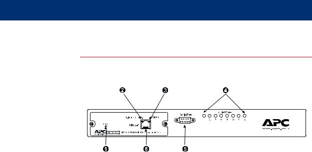
Front panel
.
! |
Reset Button |
Re-initializes the MasterSwitch PDU without affecting the |
|
outlet state. |
|||
|
|
||
|
|
|
|
" |
Status LED |
Indicates the status of the Ethernet LAN connection and |
|
|
|
the state of the management card, as described in LEDs |
|
|
|
||
# |
Link-RX/TX LED |
on page 2. |
|
|
|
|
|
$ |
Eight Outlet |
Indicates whether the associated outlet is on. |
|
Power LEDs |
|||
|
|
||
|
|
|
|
% |
Serial Port |
Connects the MasterSwitch PDU to a terminal emulator |
|
program to access the Control Console. |
|||
|
|
||
|
|
|
|
|
|
Connects the MasterSwitch PDU to an Ethernet LAN |
|
& |
RJ-45 Port |
using the 10Base-T communication cable. This |
|
connection allows configuration of the MasterSwitch PDU |
|||
|
|
||
|
|
through the Web, Telnet, or SNMP. |
|
|
|
|
|
|
|
Continued on next page |
MasterSwitch Power Distribution Unit User’s Guide |
1 |

Introduction
Product Description continued
LEDs |
Each outlet has a corresponding LED that indicates the state of the |
||||
|
outlet, and two LEDs indicate the status of the entire unit. The following |
||||
|
table describes the conditions indicated by the LEDs. |
||||
|
|
|
|
|
|
|
|
LED |
Status |
Description |
|
|
|
|
|
|
|
|
|
Outlet LED |
On |
The Outlet is on. |
|
|
|
|
|
|
|
|
|
Off |
The Outlet is off. |
|
|
|
|
|
|
||
|
|
|
|
|
|
|
|
|
Off |
The MasterSwitch PDU has no power. |
|
|
|
|
|
|
|
|
|
|
Green |
The MasterSwitch PDU has valid network |
|
|
|
|
settings. |
|
|
|
|
|
|
|
|
|
|
|
|
|
|
|
|
|
Flashing |
The MasterSwitch PDU does not have valid |
|
|
|
Status |
Green |
network settings. |
|
|
|
|
|
|
|
|
|
|
Red |
A hardware failure has been detected in the |
|
|
|
|
MasterSwitch PDU. |
|
|
|
|
|
|
|
|
|
|
|
|
|
|
|
|
|
Blinking |
The MasterSwitch PDU is making BOOTP |
|
|
|
|
Red |
requests. |
|
|
|
|
|
|
|
|
|
|
|
The device that connects the MasterSwitch |
|
|
|
|
Off |
PDU to the network (a router, hub, or |
|
|
|
Link-RX/TX |
|
concentrator) is off or is not operating correctly. |
|
|
|
|
|
|
|
|
|
|
Flashing |
The MasterSwitch PDU is receiving data |
|
|
|
|
Green |
packets from the network. |
|
|
|
|
|
|
|
Continued on next page
MasterSwitch Power Distribution Unit User’s Guide |
2 |

Introduction
Product Description continued
Rear panel |
The following table lists the features of the MasterSwitch rear panel |
|||
|
shown in the figures on this page. |
|||
|
|
|
|
|
|
|
! |
Power Cord/ IEC Inlet |
|
|
|
|
|
|
|
|
" |
Outlets |
|
|
|
|
|
|
|
|
# |
Outlet Label |
|
|
|
|
|
|
|
|
$ |
Circuit Breaker |
|
|
|
|
|
|
The following figure shows the MasterSwitch (AP9211/AP9217) rear panel with NEMA 5-15 outlets.
The following figure shows the MasterSwitch (AP9212/ AP9218) rear panel with IEC-320 C13 outlets.
|
|
|
|
MasterSwitch Power Distribution Unit User’s Guide |
3 |
||

Introduction
Initial Setup
Required network |
You must configure the following network settings of the MasterSwitch |
settings |
PDU before it can operate on a network: |
|
• IP address of the unit |
|
• Subnet Mask |
|
• IP address of the default gateway |
|
Note: If a default gateway is not present, enter an IP address |
|
of a computer that is on the same subnet and that is |
|
always active. |
Configuring TCP/IP |
To configure TCP/IP settings, see TCP/IP on page 15 and see the |
settings |
MasterSwitch Installation and Quick Start Manual, included in printed |
|
form with the MasterSwitch PDU and in Portable Document Format |
|
(Install.pdf) on this CD-ROM. |
Customizing your |
After you configure MasterSwitch network settings, no further |
configuration |
configuration is required. The remaining MasterSwitch properties are |
|
pre-configured to default settings at the factory. However, you may want |
|
to customize these properties for your application. For more information, |
|
see Managing the MasterSwitch PDU on page 5. |
Auto-configuration |
The management card within the MasterSwitch PDU supports an auto- |
|
configuration utility that you can use to create a configuration file, which |
|
you can then download to other MasterSwitch PDUs, either to individual |
|
units one at a time or to multiple units at the same time. For more |
|
information, see the Management Card Addendum (addendum.pdf |
|
on the MasterSwitch CD-ROM). |
MasterSwitch Power Distribution Unit User’s Guide |
4 |

 MasterSwitch Power Distribution Unit
Managing the MasterSwitch PDU
Management Interfaces
Management |
After you configure a MasterSwitch PDU with the proper network |
Options |
settings, you can manage the unit remotely through its Web, Telnet |
|
Control Console, SNMP, and WAP interfaces. |
|
You can also use the Control Console to manage a MasterSwitch PDU |
|
locally through a serial connection. |
|
Only one user at a time can access a MasterSwitch PDU. Serial |
|
interface users (using a terminal emulator) have precedence over Telnet |
|
users, and Telnet users have precedence over Web and WAP users. |
Web interface To access and log on to the Web interface of the MasterSwitch PDU:
1.In the URL Location field of the Web browser, do one of the following:
•If the Web port of the MasterSwitch PDU is set to the default value of 80, enter http:// followed by the unit’s IP address. The following example shows a typical IP address:
http://170.241.17.51
•If the Web port of the MasterSwitch PDU is set to a value other than the default of 80, enter the System IP address (the IP address of the unit) followed by a colon and the configured Web port value (8000 in the following example).
http://170.241.17.51:8000
•If there is a DNS server entry for the MasterSwitch PDU, you can choose to enter the DNS name to access the unit.
Continued on next page
MasterSwitch Power Distribution Unit User’s Guide |
5 |

Managing the MasterSwitch PDU
Management Interfaces continued
Web interface, |
2. Respond to the user name and password prompts. The default for |
continued |
both the Administrator user name and the Administrator password is |
|
apc (lowercase). After you log on, you can change the user name, |
|
password, and time-out values through the System menu. See User |
|
Manager on page 18. |
|
Note: Some Web interface features (data verification, Assistant |
|
Online, and MD5 authentication) require that you enable |
|
JavaScript or Java on your web browser, and MD5 |
|
authentication also requires that you have cookies enabled. |
Control Console In addition to or instead of using the Web interface, you can use the interface Control Console to manage the MasterSwitch PDU by one of the
following modes of access:
•Telnet, for remote management.
•A serial interface, for local management.
Telnet. To access the unit’s Control Console:
1.Choose Connect, then Remote Server.
2.Type the IP address of the MasterSwitch PDU.
3.Click the Connect button.
Continued on next page
MasterSwitch Power Distribution Unit User’s Guide |
6 |
Managing the MasterSwitch PDU
Management Interfaces continued
Control Console |
Serial Interface. To access the unit’s Control Console, use the supplied |
|||
interface, |
null-modem cable to connect the serial port of the computer to the serial |
|||
continued |
port on the MasterSwitch PDU, and set the terminal port to the following |
|||
|
communication settings: |
|
|
|
|
|
|
|
|
|
|
Baud Rate |
2400 |
|
|
|
|
|
|
|
|
Data Bits |
8 |
|
|
|
|
|
|
|
|
Stop Bits |
1 |
|
|
|
|
|
|
|
|
Parity |
None |
|
|
|
|
|
|
|
|
Handshaking |
None |
|
|
|
|
|
|
|
|
Local Echo |
Off |
|
|
|
|
|
|
|
|
Terminal Type |
ANSI (VT100) |
|
|
|
|
|
|
Logging on. To log on to the Control Console using either Telnet or a serial interface, respond to the user name and password prompts.The default for both the Administrator user name and the Administrator password is apc (lowercase).
Note: You can change the user name, password, and time-out values through the System menu. See User Manager on page 18.
Using menu items. All menus of the Control Console list items by number and name.
•To select an item, type the number, and press ENTER.
•For menus that configure value, always use the Accept Changes option to save any changes that you make.
SNMP interface MasterSwitch fully supports SNMP—all unit and outlet properties are configurable through SNMP. For instructions on how to use SNMP to manage MasterSwitch, see the Mibguide.pdf and the NMS.pdf files in the Snmp folder on the CD.
Continued on next page
MasterSwitch Power Distribution Unit User’s Guide |
7 |

Managing the MasterSwitch PDU
Management Interfaces continued
WAP Interface To access and log on to the WAP (Wireless Application Protocol) interface of the MasterSwitch PDU:
1.In the URL Location field of the Micro browser:
Enter the unit’s IP address followed by wap.wml. The following example shows a typical address:
123.456.78.9/wap.wml
2.Respond to the user name and password prompts. If it has not been changed since purchase, the default for both the Administrator user name and the Administrator password is apc (lowercase).
Depending on the level of access (Administrator, Device Manager or Outlet User), the WAP interface will display outlets assigned to the user who logged on and will offer the following control options for the MasterSwitch unit:
•immediate on
•immediate off
•reboot
•master control of all outlets (All).
Note: The character preceding each outlet indicates whether the outlet is on (+) or off (–).
MasterSwitch Power Distribution Unit User’s Guide |
8 |

Managing the MasterSwitch PDU
Password-Protected Accounts
Account access There are up to 16 Outlet User accounts, one Administrator account, and one Device Manager account. Each type of account provides a different level of access to the management menus.
•Each Outlet User account has access only to the outlets assigned to it.
•The Administrator and Device Manager accounts have access to all outlets.
•The Administrator account can configure and manage all other accounts.
|
|
Account Type |
|
|
Menu Items |
|
|
|
|
Administrator |
Device Manager |
Outlet User |
||
|
||||
|
|
|
|
|
Outlets |
Yes |
Yes |
Yes |
|
|
|
|
|
|
MasterSwitch |
Yes |
Yes |
No |
|
|
|
|
|
|
Event Log |
Yes |
Yes |
No |
|
|
|
|
|
|
Network |
Yes |
No |
No |
|
|
|
|
|
|
System |
Yes |
No |
No |
|
|
|
|
|
|
Logout |
Yes |
Yes |
Yes |
|
|
|
|
|
|
Help |
Yes |
Yes |
Yes |
|
|
|
|
|
|
Links |
Yes |
Yes |
Yes |
|
|
|
|
|
For instructions on configuring Device Manager and Outlet User accounts, see User Manager on page 18.
MasterSwitch Power Distribution Unit User’s Guide |
9 |

 MasterSwitch Power Distribution Unit
Menu Items
Introduction
Management |
Both the Web and Control Console interfaces provide the capabilities |
Options |
that this section describes for managing the MasterSwitch PDU, but the |
|
information in this section is based on the Web interface. If you are |
|
using Telnet or a serial interface to access the MasterSwitch PDU, |
|
terminology may differ from what is used here. |
|
Menu access depends on which type of account has logged on. See |
|
Password-Protected Accounts on page 9 for more information on |
|
accounts. |
|
Note: SNMP information appears in a separate document, |
|
Mibguide.pdf, on this CD-ROM. |
MasterSwitch Power Distribution Unit User’s Guide |
10 |

Menu Items
Outlets
Outlet Control You can perform the following Outlet Control Actions on individual Actions outlets or on all accessible outlets as a group (by Master Outlet Control).
You can apply a Control Action only to an outlet that is not executing a command.
Item |
Definition |
|
|
|
|
Immediate On |
The outlet turns on. |
|
|
|
|
Immediate Off |
The outlet turns off. |
|
|
|
|
Immediate Reboot |
The outlet turns off immediately, waits the outlet’s Reboot |
|
Duration time, and turns on. |
||
|
||
|
|
|
Delayed On |
The outlet turns on according to its Power On Delay. |
|
|
|
|
Delayed Off |
The outlet turns off according to its Power Off Delay. |
|
|
|
|
|
All outlets in the group assigned to the outlet user |
|
Sequenced Reboot |
immediately turn off. Each outlet then waits the longest |
|
Reboot Duration (in seconds) of any outlet in the group, |
||
|
||
|
waits its own Power On Delay, and turns on. |
|
|
|
|
Delayed Reboot |
The outlet turns off after its Power Off Delay, waits its own |
|
Reboot Duration, and turns on. |
||
|
||
|
|
|
|
Each outlet in the group of accessible outlets does the |
|
|
following: |
|
Delayed Sequenced |
1. Waits its own Power Off Delay. |
|
2. Turns off. |
||
Reboot |
3. Waits the longest Reboot Duration time (in seconds) of |
|
|
any outlet in the group. |
|
|
4. Waits its own Power On Delay. |
|
|
5. Turns on. |
|
|
|
|
|
All pending commands are canceled for the outlet(s). |
|
Cancel Pending |
Note: The Outlet State appears in orange with an asterisk |
|
Commands |
(*), indicating that a command is pending for the |
|
|
outlet(s). |
|
|
|
MasterSwitch Power Distribution Unit User’s Guide |
11 |
Menu Items
MasterSwitch |
|
|
Configure Device |
|
|
Settings |
Item |
Definition |
|
||
|
|
|
|
Unit Name |
The name of the MasterSwitch PDU. |
|
Maximum: 23 characters. |
|
|
|
|
|
|
|
|
Coldstart Delay |
The time that the MasterSwitch PDU waits before applying |
|
power to outlets after AC power is applied to the unit. |
|
|
|
|
|
|
|
|
|
The longest reboot duration of any outlet in the group of |
|
|
accessible outlets. You can change this value only by |
|
Reboot Duration |
modifying the Reboot Duration of individual accessible |
|
|
outlets. Sequenced Reboot and Delayed Sequenced Reboot |
|
|
use this value. |
Outlet |
|
|
|
|
|
Configuration |
Item |
Definition |
|
||
|
|
|
|
Outlet Name |
The name that identifies the outlet. |
|
Maximum: 23 characters. |
|
|
|
|
|
|
|
|
|
The time that the outlet waits before turning on after the |
|
Power On Delay |
command is issued. Delayed On, Sequenced Reboot, and |
|
|
Delayed Sequenced Reboot use this value. |
|
|
|
|
|
The time that the outlet waits before turning off after the |
|
Power Off Delay |
command is issued. Delayed Off, Delayed Reboot, and |
|
|
Delayed Sequenced Reboot use this value. |
|
|
|
|
Reboot Duration |
The time that the outlet will remain off during a reboot. |
|
Immediate Reboot and Delayed Reboot use this value. |
|
|
|
|
|
|
|
|
URL Links |
Defines HTTP links to relevant Web pages. |
|
|
|
MasterSwitch Power Distribution Unit User’s Guide |
12 |

Menu Items
Event Log
Displaying the |
To display the Event Log, select the Event Log menu in the Web |
|||
Event Log |
interface or press CTRL + L in the Control Console interface. |
|||
|
The Event Log displays the following information for the most recent 300 |
|||
|
events for the MasterSwitch PDU. |
|||
|
|
|
|
|
|
|
Item |
Description |
|
|
|
|
|
|
|
|
Date |
The date on which the event occurred (DD/MM/YYYY) |
|
|
|
|
|
|
|
|
Time |
The time at which the event occurred (HH:MM:SS) |
|
|
|
|
|
|
|
|
Event |
Description of the event. |
|
|
|
|
|
|
Retrieving the Event Log by using FTP
To retrieve the Event Log using client-side FTP:
1.From an MS-DOS prompt, type ftp card-ip, where card-ip is the IP address of your MasterSwitch PDU.
2.After you log into the unit's FTP server, type dir. The screen displays information similar to the following:
ftp>dir
200 Command okay.
150 Opening data connection for /.
--wx-wx-wx 1 apc apc 262144 Jul 5 2000 aos253.bin --wx-wx-wx 1 apc apc 458752 Jul 5 2000 msp202.bin -r--r--r-- 1 apc apc 4096 Jul 5 2000 event.txt 226 Closing data connection.
ftp: 194 bytes received in 0.00Seconds 194000.00Kbytes/sec.
ftp>
Continued on next page
MasterSwitch Power Distribution Unit User’s Guide |
13 |

Menu Items
Event Log continued
Retrieving the |
3. Type get event.txt. The MasterSwitch PDU transmits the Event |
|
Event Log by using |
Log, containing at least the last 300 events, to your specified drive. |
|
FTP, continued |
The screen displays information similar to the following. |
|
|
|
ftp>get event.txt |
|
|
200 Command okay. |
|
|
150 Opening data connection for event.txt |
|
|
226 Closing data connection. |
|
|
ftp: 3694 bytes received in 0.11Seconds |
|
|
33.58Kbytes/sec. |
|
|
ftp> |
Using a |
To view the event.txt file after you obtain it, use a spreadsheet |
|
spreadsheet to |
application. The file is TAB-delimited for automatic formatting of |
|
view the Event Log |
columns. |
|
|
Note: |
When you import the event.txt file into a spreadsheet, the |
|
|
spreadsheet may display the year in the date fields as only two |
|
|
digits instead of the four digits logged and displayed by the |
|
|
MasterSwitch PDU. To display the year as four digits, select a |
|
|
four-digit date format in the spreadsheet. |
|
The event.txt file also includes the following information that is not |
|
|
shown in the Web and Control Console Event Log screens: |
|
|
• |
The version of the event.txt file format (first field). |
|
• |
The date and time at which the event.txt file was retrieved. |
|
• |
The Name, Contact, Location, and IP address for the unit’s |
|
|
Management Card. |
|
• |
A unique Event Code for every type of event. |
Deleting the Event |
To delete the Event Log, type del event.txt. You are not prompted |
|
Log in the FTP |
to confirm the deletion. The screen displays information similar to the |
|
interface |
following: |
|
ftp>del event.txt
250 Requested file action okay, completed. ftp>
A new event.txt file is created immediately in response to the Deleted
Log event.
MasterSwitch Power Distribution Unit User’s Guide |
14 |
 Loading...