


 Loading...
Installation and
Quick Start
Rack Automatic
Transfer Switch

This manual is available in English on the enclosed CD.
Dieses Handbuch ist in Deutsch auf der beiliegenden CD-ROM verfügbar. Este manual está disponible en español en el CD-ROM adjunto.
Ce manuel est disponible en français sur le CD-ROM ci-inclus.
Questo manuale è disponibile in italiano nel CD-ROM allegato.
CD-ROM
Instrukcja Obsługi w jezyku polskim jest dostepna na CD.
O manual em Português está disponível no CD-ROM em anexo.
Данное руководство на русском языке имеется на прилагаемом компакт-диске.
Bu kullanim kilavuzunun Türkçe'sä, äläxäkte gönderälen CD äçeräsände mevcuttur.
CD

Contents
Preliminary Information.................................................. |
1 |
Overview. . . . . . . . . . . . . . . . . . . . . . . . . . . . . . . . . . . . . . . . . . . . . . . . 1
Additional documentation . . . . . . . . . . . . . . . . . . . . . . . . . . . . . . . . . 1
Receiving inspection . . . . . . . . . . . . . . . . . . . . . . . . . . . . . . . . . . . . . . 1
Please recycle . . . . . . . . . . . . . . . . . . . . . . . . . . . . . . . . . . . . . . . . . . . 1
Product inventory . . . . . . . . . . . . . . . . . . . . . . . . . . . . . . . . . . . . . . . . 2
Additional options . . . . . . . . . . . . . . . . . . . . . . . . . . . . . . . . . . . . . . . . 2
Overview .......................................................................... |
3 |
Front panel . . . . . . . . . . . . . . . . . . . . . . . . . . . . . . . . . . . . . . . . . . . . . . |
3 |
Installation ....................................................................... |
5 |
Mounting options. . . . . . . . . . . . . . . . . . . . . . . . . . . . . . . . . . . . . . . . . |
5 |
Quick Configuration........................................................ |
6 |
Overview . . . . . . . . . . . . . . . . . . . . . . . . . . . . . . . . . . . . . . . . . . . . . . . . 6 TCP/IP configuration methods. . . . . . . . . . . . . . . . . . . . . . . . . . . . . . . 6
Device IP Configuration Wizard . . . . . . . . . . . . . . . . . . . . . . . . . . . . . 6
BOOTP & DHCP configuration . . . . . . . . . . . . . . . . . . . . . . . . . . . . . . 7
Local access to the control console . . . . . . . . . . . . . . . . . . . . . . . . . 8
Remote access to the control console . . . . . . . . . . . . . . . . . . . . . . . 8
Control console . . . . . . . . . . . . . . . . . . . . . . . . . . . . . . . . . . . . . . . . . . 9
How to Access the Rack ATS Interfaces .................... |
10 |
Overview. . . . . . . . . . . . . . . . . . . . . . . . . . . . . . . . . . . . . . . . . . . . . . . 10
Web interface . . . . . . . . . . . . . . . . . . . . . . . . . . . . . . . . . . . . . . . . . . . 10
Telnet and SSH . . . . . . . . . . . . . . . . . . . . . . . . . . . . . . . . . . . . . . . . . 10
SNMP . . . . . . . . . . . . . . . . . . . . . . . . . . . . . . . . . . . . . . . . . . . . . . . . . 11
FTP and SCP . . . . . . . . . . . . . . . . . . . . . . . . . . . . . . . . . . . . . . . . . . . 12
Managing the security of your system . . . . . . . . . . . . . . . . . . . . . . 12
Automatic Transfer Switch—Installation and Quick Start |
i |
Configuring the Rack ATS............................................ |
13 |
Configuring sensitivity. . . . . . . . . . . . . . . . . . . . . . . . . . . . . . . . . . . . |
13 |
Configuring voltage transfer range. . . . . . . . . . . . . . . . . . . . . . . . . . |
13 |
Recovering From A Lost Password............................. |
14 |
Warranty......................................................................... |
15 |
Terms of warranty . . . . . . . . . . . . . . . . . . . . . . . . . . . . . . . . . . . . . . . 15
Non-transferable warranty. . . . . . . . . . . . . . . . . . . . . . . . . . . . . . . . . 15
Exclusions. . . . . . . . . . . . . . . . . . . . . . . . . . . . . . . . . . . . . . . . . . . . . . 15
Warranty claims . . . . . . . . . . . . . . . . . . . . . . . . . . . . . . . . . . . . . . . . . 16
Life-Support Policy........................................................ |
17 |
General policy. . . . . . . . . . . . . . . . . . . . . . . . . . . . . . . . . . . . . . . . . . . 17
Examples of life-support devices . . . . . . . . . . . . . . . . . . . . . . . . . . . 17
ii |
Automatic Transfer Switch—Installation and Quick Start |

Preliminary Information
Overview
The American Power Conversion (APC®) Rack Automatic Transfer Switch (ATS) is a high-availability switch that provides redundant power to connected equipment and has two input power cords, one for each AC line. The Rack ATS supplies power to the connected load from a primary AC source. If that primary source becomes unavailable, the Rack ATS automatically begins sourcing power from the secondary source. The transfer time from one source to the other is seamless to the connected equipment, as the switching occurs safely between the two input sources regardless of any phase differences. The units have built-in network connectivity, which allows for remote management through the Web, SNMP, or Telnet interfaces.
Additional documentation
This Installation and Quick Start manual and the online User’s Guide are available on the supplied CD or on the APC Web site, www.apc.com. The online User’s Guide contains additional information about the following topics related to the Rack ATS:
•Management interfaces
•User accounts
•Customizing setup
•Security
Receiving inspection
Inspect the package and contents for shipping damage, and make sure that all parts were sent. Report any shipping damage immediately to the shipping agent, and report missing contents, damage, or other problems immediately to APC or your APC reseller.
Please recycle
The shipping materials are recyclable. Please save them for later use, or dispose of them appropriately.
Automatic Transfer Switch—Installation and Quick Start |
1 |
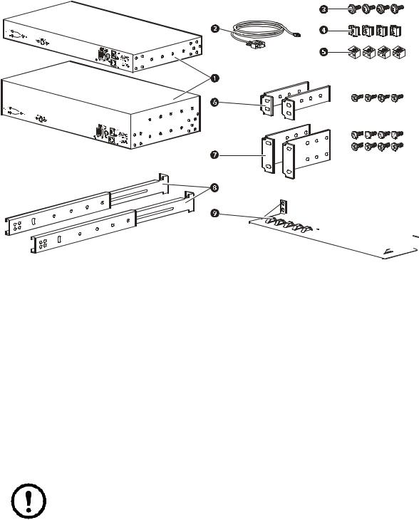
Product inventory


 pdu0393a
Rack Automatic Transfer Switch (1 U or 2 U)
Communication cable - RJ12 to female DB-9
Screw
Cage nut
Clip-on retainer
1-U rack-mount bracket kit (provided with 1-U Rack ATS)
2-U rack-mount bracket kit (provided with 2-U Rack ATS)
Additional options
Front and rear rail segments AP7768 (not provided)
Cord retention bracket AP7769 (not provided)
Note: Install the Rack ATS with front and rear rail segments for increased stability. The front/rear rail segments and cord retention bracket are available on the APC Web site, www.apc.com.
2 |
Automatic Transfer Switch—Installation and Quick Start |
Overview
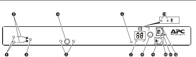
Front panel
Input |
A |
Output |
Preference |
|
|||
|
B |
||
|
B |
A |
|
|
|
|
B1 |
|
B2 |
- OK |
TOTA L |
- Warning |
||
|
|
- Overload |
|
|
|
|
- OK |
Link - Rx/Tx |
|
- Warning |
10/100 |
|
- Overload |
|
|
|
Status |
|
Press to |
Automatic |
|
select data |
Transfer Switch |
|
Amps |
||
|
||
Reset |
Serial Port |
pdu0392a
|
Item |
Description |
|
|
|
|
Source A and B LEDs |
Provide information about the input voltage from each source. |
|
|
If the RMS input voltage and the measured frequency are |
|
|
within the selected tolerance range, the corresponding indicator |
|
|
will light. |
|
|
In a normal operating condition (full source redundancy), both |
|
|
LEDs are illuminated. |
|
|
|
|
Connector LEDs |
Indicate which source is being used for the output (only one |
|
|
arrow will be lit at any time). The combination of Source |
|
|
LEDs, Connector LEDs, and Output LED provide a graphical |
|
|
view of the power flow through the ATS. |
|
|
|
|
Output LED |
Shows that voltage is available at the output for the ATS. |
|
|
|
|
Preference key |
Sets the preferred source to supply power to the load |
|
|
equipment. In normal operation, if both sources are available, |
|
|
the ATS will use the preferred source. Press the Preference key |
|
|
to change the preferred source. Press and hold for ten seconds |
|
|
to restart the ATS. The restart occurs without resetting |
|
|
communications and is confirmed when both status LEDs flash |
|
|
off, then on. |
|
|
|
|
Preference A and B |
Indicate which of the two sources is selected as the preferred |
|
LEDs |
source. If both LEDs are off, neither source is selected. If the |
|
|
sources are asynchronous, the LED for the selected source will |
|
|
flash once per second. |
|
|
|
|
Reset switch |
Restarts ATS network and serial communication. |
|
|
|
|
Digital display |
Digital display of the current used by the ATS and attached |
|
|
devices: |
|
|
• Shows the aggregate current for the bank/phase |
|
|
corresponding to the Bank/Phase Indicator LED that is |
|
|
illuminated. |
|
|
• Cycles through the banks/phases in 3-second intervals. |
|
|
|
|
Control key |
• Press to change the bank/phase of the current displayed on the |
|
|
digital display. |
|
|
• Press and hold for five seconds to display the IP address of the |
|
|
ATS. |
|
|
|
Automatic Transfer Switch—Installation and Quick Start |
3 |
|
Item |
Description |
|
|
|
|
Serial port |
Access internal menus by connecting this port (an RJ-11 |
|
|
modular port) to a serial port on your computer, using the |
|
|
supplied communication cable. |
|
|
|
|
Ethernet port |
Connects the ATS to your network using a CAT5 network |
|
|
cable. |
|
|
|
|
Status LED |
Indicates the status of the Ethernet LAN connection and the |
|
|
state of the ATS. |
|
|
• Off–The ATS has no power. |
|
|
• Solid green–The ATS has valid TCP/IP settings. |
|
|
• Flashing green–The ATS does not have valid TCP/IP |
|
|
settings. |
|
|
• Solid orange–A hardware failure has been detected in the |
|
|
ATS. Contact Customer Support at a phone number on the |
|
|
back cover of this manual. |
|
|
• Flashing orange–The ATS is making BOOTP requests. |
|
|
|
|
Link LED |
Indicates whether there is activity on the network. |
|
|
|
|
Bank/phase indicator |
• Indicate the bank/phase corresponding to the current shown in |
|
LEDs |
the digital display. |
|
|
• Indicate normal (green), warning (yellow), or alarm (red) |
|
|
condition. |
|
|
Note: The 2-U Rack ATS indicates which bank is displayed |
|
|
with LEDs for B1 and B2. |
|
|
|
4 |
Automatic Transfer Switch—Installation and Quick Start |
Loading...