


1250
Smart-UPS
®
Models 900,
1250 and 2000
User'sUser's
User'sUser's
User's
ManualManual
ManualManual
Manual
TM

Important safety instructions!
Please read this manual!
Veuillez lire ce manuel!
Bitte lesen Sie dieses Anleitungshandbuch!
¡Se ruega leer este manual de instrucciones!
This manual provides safety, installation and operating instructions that will help you derive
the fullest performance and service life that the UPS has to offer.
PLEASE SAVE THIS MANUAL ! It includes important instructions for the safe use of this UPS
and for obtaining factory service should the proper operation of the UPS come into question.
Down the road, service or storage issues may arise and require reference to this manual.
CONSERVER CES INSTRUCTIONS ! Cette notice contient des instructions importantes
concernant la sécurité.
Radio Frequency Interference
WARNING: Changes or modifications to this unit not expressly approved by the party
responsible for compliance could void the user's authority to operate the equipment.
NOTE: This equipment has been tested and found to comply with the limits for a Class A digital
device pursuant to Part 15 of the FCC Rules. These limits are designed to provide reasonable
protection against harmful interference when the equipment is operated in a commercial
environment. This equipment generates, uses, and can radiate radio frequency energy and, if
not installed and used in accordance with the instruction manual, may cause harmful interfer-
ence to radio communications. Operation of this equipment in a residential area is likely to
cause harmful interference in which case the user will be required to correct the interference at
his own expense.
Shielded signaling cables must be used with this unit to ensure compliance with the Class A
FCC limits.
This digital apparatus does not exceed the Class A limits for radio noise emissions from digital
apparatus set out in the Radio Interference Regulations of the Canadian Department of
Communications.
Le présent appareil numérique n'emet pas de bruits radioélectriques dépassant les limites
applicables aux appareils numériques de la Class A prescrites dans le Règlement sur le
brouillage radioélectrique édicte par le ministère dès Communications du Canada.
Hiermit wird bescheinigt, dass der
Smart-UPS 900, 1250, 2000 Ununterbrechbare Stromver-
sorgungs-Gerät in Unereinstimmung mit den Bestimmungen der Vfg 1046/1984 funk-entstort
ist. Der Deutschen Bundespost wurde das Inverkehrbringen diese Gerates angezeigt und die
Berechtigung zur Uberprufung der Serie auf Einhaltung der Bestimmungen eingeraumt.
VCCI-1*

Page 1
Table of contents
1.0 Introduction...................................................................... 2
2.0 Safety! .............................................................................. 4
Sécurité! (Français) ............................................................................................... 5
Sicherheit! (Deutsch) ............................................................................................ 6
¡Seguridad! (Español)........................................................................................... 7
3.0 Presentation ..................................................................... 8
900VA and 1250VA models.................................................................................. 8
2000VA models.................................................................................................... 10
4.0 Installation ..................................................................... 14
5.0 Operation ....................................................................... 18
6.0 UPS monitoring ..............................................................26
7.0 Difficulty ......................................................................... 28
Difficulté (Français) ............................................................................................ 29
Schwierigkeit (Deutsch)..................................................................................... 30
Dificultad (Español) ........................................................................................... 31
8.0 Storing the UPS .............................................................. 35
9.0 Specifications .................................................................. 36
Typical run time versus load ............................................................................. 38
Page 2
1.0 Introduction
1.1 Overview
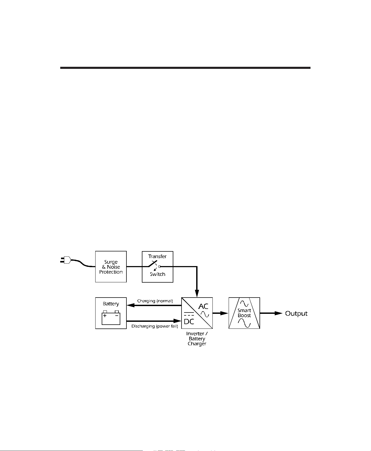
This equipment is a high performance line interactive uninterruptible power source
(UPS) designed to provide clean, reliable AC power to computer loads. The UPS's line
interactive circuit topology, illustrated below, of fers excellent efficiency , on-line voltage
regulation and fast utility fault response.
The UPS’s DC-to-AC inverter is always connected to the output and when operating on-
line, a portion of the inverter circuitry is put to work “in reverse” to continuously
maintain optimum float charge on the battery . The inverter cir cuitry also acts to protect
the load from surges and EMI/RFI noise as part of an advanced hybrid sur ge suppres-
sion and filtering network. A unique mode of operation, named SmartBoost, serves to
regulate the load voltage by compensating for brownouts or sags. This is accomplished
without the need to draw power from the UPS’s battery . In anticipation of utility failur e,
the UPS continuously monitors the line and prepares the inverter frequency for
synchronous transfer of the load. Upon occurrence of utility voltage failure such as a
blackout, severe brownout or an overvoltage condition, the UPS transfers the load to
power derived from the battery. Transfer to the "on-battery" mode of operation takes
place typically within 2 milliseconds. The inverter's output voltage waveshape is a low
distortion sine wave. Resynchronization and retransfer to on-line operation is auto-
matic upon recovery of the line voltage to within normal limits.
Line interactive UPS block diagram

Page 3
1.0 Introduction
1.2 SmartBoost
SmartBoost allows continuous on-line operation during extended brownouts or low
line voltage conditions. The UPS compensates for the reduced line voltage by boosting
the load voltage to a value 12% above the input. Reliability is enhanced because the
limited battery capacity is saved for complete utility failures.
1.3 Battery replacement indicators and test
The UPS provides both visual and audible Replace Battery indications. The indications
are based on the result of an actual load test on the battery. By exercising the UPS’s
battery during a startup test, the UPS is able to detect a weak battery before it is put into
service. In applications where the UPS is not turned off daily, or where the UPS is
purposely left operating unattended, the UPS automatically conducts this self test
every 14 days.
1.4 Remote interfaces
The UPS provides a remote computer interface capable of full bidirectional RS-232
communications. When combined with PowerDoctor UPS monitoring software and a
serially connected local DOS PC, power quality related events can be logged. Power-
Chute plus offers all the features of PowerDoctor , plus the ability to control orderly and
unattended network or multi-user computer system shutdown during an extended
power outage. Also available for the UPS is the SNMP (Simple Network Management
Protocol) Adapter to provide load type independent remote monitoring and manage-
ment across Ethernet or Token Ring based LANs or WANs capable of routing IP
messages. Using any standard Network Management System (NMS) and the SNMP
Adapter , the UPS becomes manageable through a single familiar interface - from across
your building to across the world.
1.5 Extended capabilities
Via the UPS's remote interface, the user can access advanced monitoring, power
management and operation customizing functions. Monitored parameters include
available run time, line voltage, line frequency, output power, output voltage, battery
capacity, battery voltage and internal temperature. Power management functions
include scheduled shutdown, power failure simulation, and remote turn off. UPS
functions that can be customized include the automatic self test and low battery
warning intervals; shut down, turn-off and turn-on delay intervals; transfer voltage;
utility fault sensitivity; and activation of the audible alarm.

Page 4
2.0 Safety !
Caution!
CAUTION !
■ T o reduce the risk of electric shock, disconnect the Uninterruptible Power Source from
the mains before installing computer interface signal cable (when used). Reconnect the
power cord only after all signalling interconnections have been made.
■ Connect the Uninterruptible Power Source to a two-pole, three-wire grounding
mains receptacle. The receptacle must be connected to appropriate branch protection
(fuse or circuit breaker). Connection to any other type of r eceptacle may result in a shock
hazard and may violate local electrical codes.
■ This Uninterruptible Power Source has an internal energy source (the battery) that
cannot be de-energized by the user . The output may be energized when the unit is not
connected to a mains supply.
■ T o properly deener gize the Uninterruptible Power Source in an emergency, move the
rear panel I/O switch to the O (off) position and disconnect the power cord from the
mains.
■ Avoid installing the Uninterruptible Power Source in locations where ther e is water
or excessive humidity.
■ Do not allow water or any foreign object to get inside the Uninterruptible Power
Source. Do not put objects containing liquid on or near the unit.
■ T o r educe the risk of overheating the Uninterruptible Power Source, avoid exposing
the unit to the direct rays of the sun. Avoid installing the unit near heat emitting
appliances such as a room heater or stove.
ENGLISH

Page 5
2.0 Sécurité !
Attention!
ATTENTION!
■ Pour réduire le risque d’électrocution, débranchez la prise principale de la source
d’alimentation permanente (Uninterruptible Power Source), avant d’installer le câble
d’interface allant à l’ordinateur (si utilisé). Ne rebranchez le bloc d’alimentation
qu’après avoir effectué toutes les connections.
■ Branchez la source d’alimentation permanente (UPS) dans une prise de courant à 3
dérivations (deux pôles et la terre). Cette prise doit être munie d’une protection
adéquate (fusible ou coupe-circuit). Le branchement dans tout autre genre de prise
pourrait entraîner un risque d’électrocution et peut constituer une infraction à la
réglementation locale concernant les installations électriques.
■ Cette source d’alimentation permanente (UPS) est munie d’une source d’énergie
interne (accumulateur) qui ne peut pas être désactivée par l’utilisateur. La prise de
sortie peut donc être sous tension même lorsque l’appareil n’est pas branché.
■ En cas d’urgence, pour désactiver corr ectement la source d’alimentation permanente
(UPS), poussez l’interrupteur du panneau arrière sur la position O (Of f) et débranchez
le cordon d’alimentation principal.
■ Ne pas installer la source d’alimentation permanente (UPS) dans un endroit où il y
a de l’eau ou une humidité excessive.
■ Ne pas laisser de l’eau ou tout objet pénétrer dans la source d’alimentation
permanente (UPS). Ne pas placer de récipients contenant un liquide sur cet appareil, ni
à proximité de celui-ci.
■ Pour éviter une surchauf fe de la source d’alimentation permanente (UPS), conservez-
la à l’abri du soleil. Ne pas installer à proximité d’appareils dégageant de la chaleur tels
que radiateurs ou appareils de chauffage.
FRANÇAIS

Page 6
2.0 Sicherheit !
Vorsicht!
VORSICHT!
■ Um die Gefahr eines elektrischen Schlages auf ein Minimum zu reduzieren, die
unterbrechungsfreie Stromversorgung vom Stromnetz trennen, bevor ggf. ein Com-
puter-Schnittstellensignalkabel angeschlossen wird. Das Netzkabel erst nach Herstellung
aller Signalverbindungen wieder einstecken.
■ Die unterbrechungsfr eie Stromversorgung an eine geer dete zweipolige Dreiphasen-
Netzsteckdose anschließen. Die Steckdose muß mit einem geeigneten Abzweigschutz
(Sicherung oder Leistungsschalter) verbunden sein. Der Anschluß der
unterbrechungsfreien Stromversorgung an einen anderen Steckdosentyp kann zu
Stromschlägen führen und gegen die örtlichen Vorschriften verstoßen.
■ Diese unterbrechungsfreie Stromversorgung besitzt eine interne Energiequelle
(Batterie), die vom Benutzer nicht abgeschaltet werden kann. Der Ausgang kann
eingeschaltet werden, wenn das Gerät nicht an das Stromnetz angeschlossen ist.
■ Um die unterbrechungsfreie Stromversorgung im Notfall ordnungsgemäß
abzuschalten, den I/O-Schalter an der Rückseite auf O (Aus) stellen und das Netzkabel
aus der Steckdose ziehen.
■ Die unterbrechungsfr eie Stromversorgung nicht an einem Ort aufstellen, an dem sie
mit Wasser oder übermäßig hoher Luftfeuchtigkeit in Berührung kommen könnte.
■ Darauf achten, daß weder Wasser noch Fremdkörper in das Innere der
unterbrechungsfreien Stromversorgung eindringen. Keine Objekte, die Flüssigkeit
enthalten, auf oder neben die unterbrechungsfreie Stromversorgung stellen.
■ Um ein Überhitzen der unterbr echungsfr eien Stromversorgung zu verhindern, das
Gerät vor direkter Sonneneinstrahlung fernhalten und nicht in der Nähe von
wärmeabstrahlenden Haushaltsgeräten (z.B. Heizgerät oder Herd) aufstellen.
DEUTSCH

Page 7
ESPAÑOL
2.0 ¡ Seguridad !
¡Atencion!
¡ATENCION!
■ Para reducir el riesgo de descarga eléctrica, desconecte de la r ed la Fuente de energía
ininterrumpible antes de instalar el cable de señalización de interfaz de la computadora
(si se usa). Vuelva a conectar el conductor flexible de alimentación solamente una vez
efectuadas todas las interconexiones de señalización.
■ Conecte la Fuente de energía ininterrumpible a un tomacorriente bipolar y trifilar con
neutro de puesta a tierra. El tomacorriente debe estar conectado a la protección de
derivación apropiada (ya sea un fusible o un disyuntor). La conexión a cualquier otro
tipo de tomacorriente puede constituir peligro de descar ga eléctrica y violar los códigos
eléctricos locales.
■ Esta Fuente de energía ininterrumpible tiene una fuente de energía interna (la batería)
que no puede ser desactivada por el usuario. La salida puede tener corriente aun
cuando la unidad no se encuentre conectada al suministro de red.
■ Para desactivar correctamente la Fuente de energía ininterr umpible en una situación
de emergencia, coloque el interruptor I/O del panel posterior en la posición O (Off -
desconectado) y desconecte de la red el conductor flexible de alimentación.
■ No instale la Fuente de energía ininterrumpible en lugares donde haya agua o
humedad excesiva.
■ No deje que en la Fuente de energía ininterrumpible entre agua ni ningún objeto
extraño. No ponga objetos con líquidos encima de la unidad ni cerca de ella.
■ Para reducir el riesgo de sobrecalentamiento, no exponga la unidad a los rayos
directos del sol ni la instale cer ca de artefactos que emiten calor , como estufas o cocinas.
Page 8
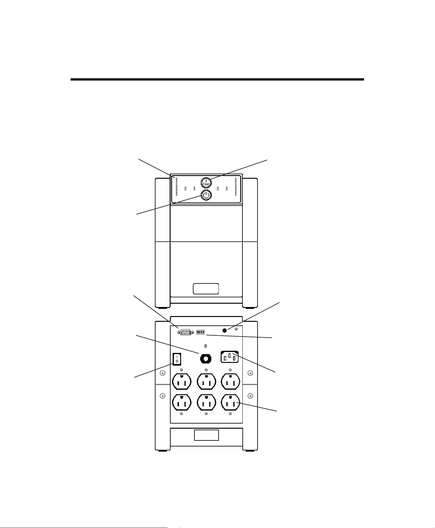
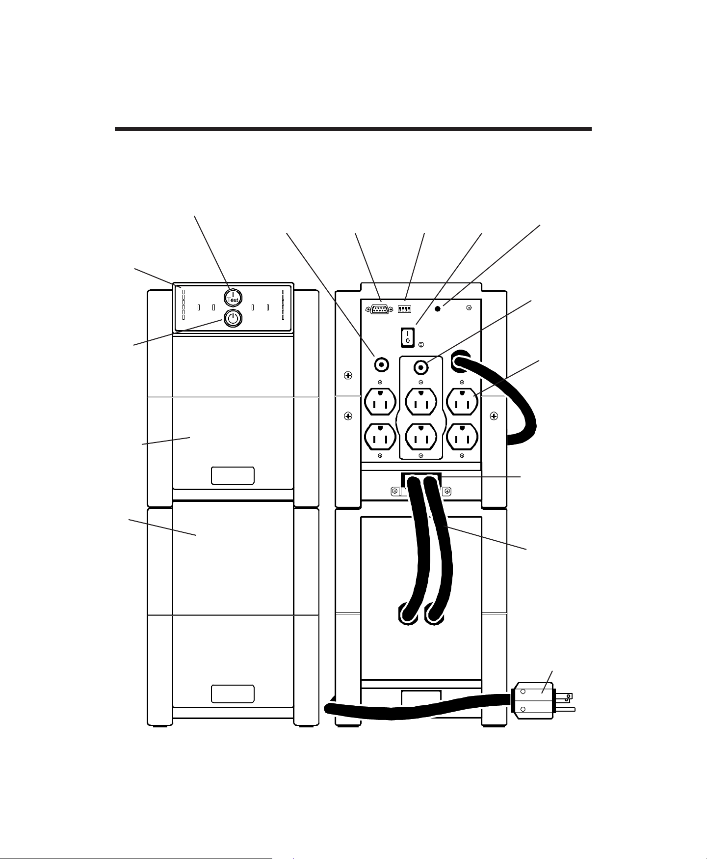
3.0 Presentation
3.1 900VA and 1250VA models - 100, 120 Vac versions
Rear view
Front view
Site wiring
fault light
See section
4.6.
UPS
enable
switch
See section
4.4.
Circuit
breaker
NEMA
5-15R
receptacles
On / Test /
Alarm disable
pushbutton
See section 5.1.
Display
features
See section
5.0.
Power
standby
pushbutton
See section
5.1.
Computer
interface
port
See section
6.0.
Option
switches
See section
5.6.
IEC 320
inlet
Page 9
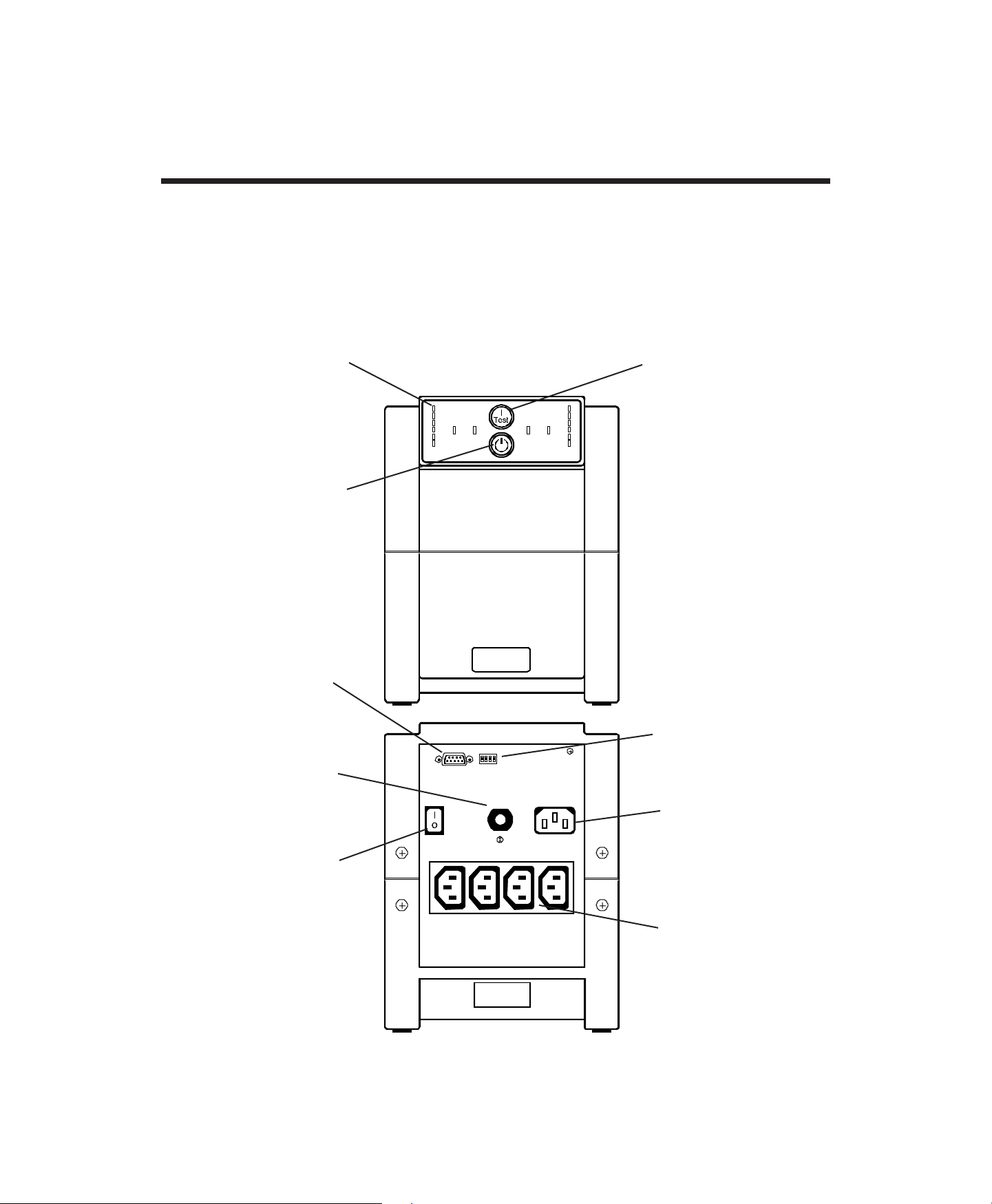
3.0 Presentation
3.2 900VA and 1250VA models - 220/230/240 Vac version
Rear view
Front view
On / Test /
Alarm disable
pushbutton
See section 5.1.
Display
features
See section
5.0.
Power
standby
pushbutton
See section
5.1.
IEC 320
output
couplers
All couplers
are
protected
by the UPS.
IEC 320
inlet
Computer
interface
port
See section
6.0.
Option
switches
See section
5.6.
Circuit
breaker
UPS
enable
switch
See section
4.4.
Page 10
3.0 Presentation
3.3 2000VA model - 100, 120 Vac versions
Front view Rear view
Power
standby
pushbutton
See section
5.1.
On / Test / Alarm
disable pushbutton
See section 5.1.
Battery
pack
Electronics
enclosure
15Amp
circuit
breaker
protects
center
receptacles
NEMA
5-15R
receptacles
Battery
pack cables
Display
features
See
section
5.0.
Computer
interface port
See section 6.0.
15Amp circuit
breaker
protects side
receptacles
Site wiring
fault light
See section
4.6.
UPS enable
switch
See section
4.4.
Option
switches
See section
5.6.
Battery pack
coupler and
UPS locking
plate
See section
4.3.
NEMA 5-15P plug
NEMA L5-30P, 5-20P
rewireable plugs
supplied as alternate.
Page 11
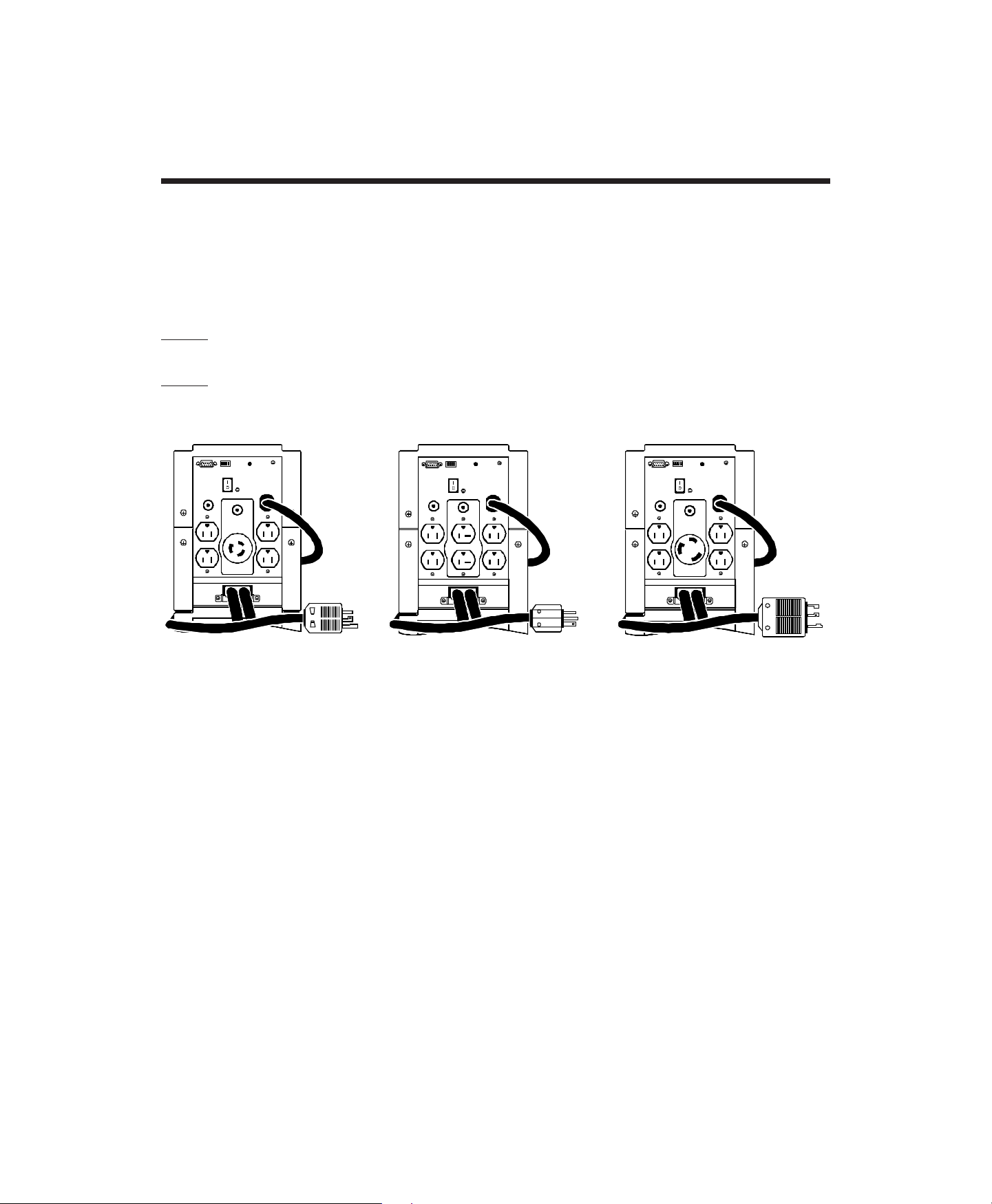
3.0 Presentation
3.4 2000VA model - 120 Vac versions options
The -1, -2 and -4 wiring device options for the 120 Vac version 2000VA model UPS are
shown below for refer ence. These options allow simple plug-in installation of the UPS
where special service or load wiring devices are used.
Note: Option -3 has been replaced by an improved standard version - it is no longer
offered.
Note: Due to the difference in available capacity of the UPS and the maximum usable
current ratings of the wiring devices, UPSs furnished with -1 and -2 wiring device
options are derated to 1850 VA.
Option -1 Option -2 Option -4
3.4.1 Option -1 UPSs have the following wiring devices:
(1) NEMA L5-20R twist lock receptacle,
(2) NEMA 5-15R duplex receptacles,
(1) NEMA L5-20P twist lock input plug.
3.4.2 Option -2 UPSs have the following wiring devices:
(1) 5-20R duplex receptacle,
(2) NEMA 5-15R duplex receptacles,
(1) NEMA 5-20P input plug.
3.4.3 Option -4 UPSs have the following wiring devices:
(1) NEMA L5-30R twist lock receptacle,
(2) NEMA 5-15R duplex receptacles,
(1) NEMA L5-30P twist lock input plug.
Page 12
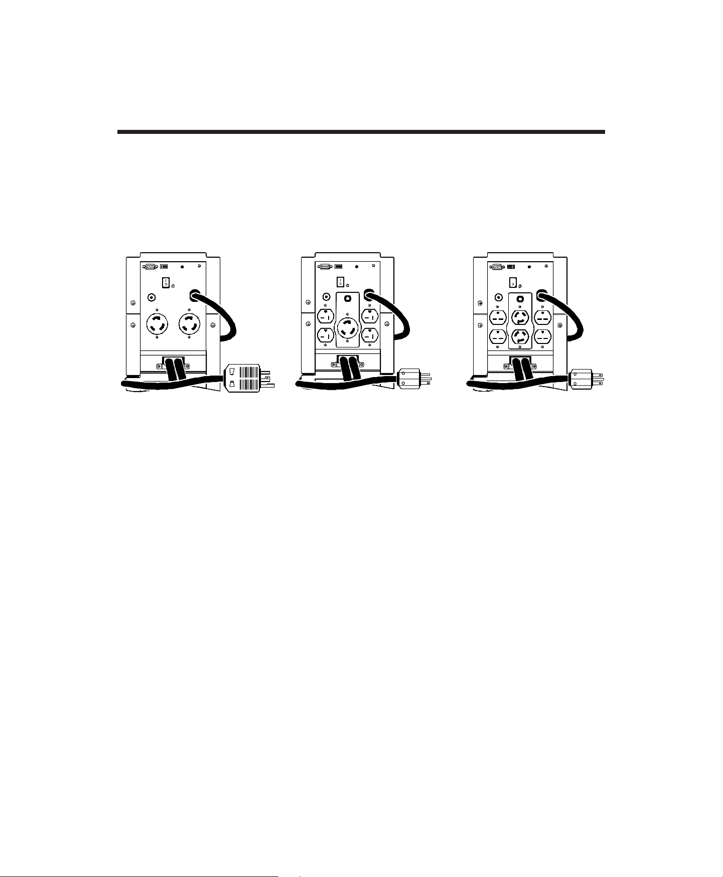
3.0 Presentation
3.5 2000VA model - 208 Vac version and options
The standard 208 Vac version 2000VA model UPS and its wiring device options are
shown below for refer ence. These options allow simple plug-in installation of the UPS
where special service or load wiring devices are used.
Standard Option -1 Option -2
3.5.1 Standard 208 Vac version UPSs have the following wiring devices:
(2) NEMA L6-30R twist lock receptacles,
(1) NEMA L6-30P twist lock input plug.
3.5.2 Option -1 208 Vac version UPSs have the following wiring devices:
(1) NEMA L6-20R twist lock receptacle,
(2) NEMA 6-20R duplex receptacles,
(1) NEMA 6-20P input plug - a NEMA L6-20P rewireable twist lock plug is provided as
an alternate.
3.5.3 Option -2 208 Vac version UPSs have the following wiring devices:
(1) NEMA L6-15R twist lock duplex receptacle,
(2) NEMA 6-15R duplex receptacles,
(1) NEMA 6-15P input plug - a NEMA L6-15P rewireable twist lock plug is provided as
an alternate.
 Loading...