


 Loading...
Installation and
Operation
J Type Power Conditioner
and Battery Backup
J25B
J35B
120 V
1440 VA/865 W
General Information........................................................ |
1 |
Overview . . . . . . . . . . . . . . . . . . . . . . . . . . . . . . . . . . . . . . . . . . . . . . . . 1
Inventory . . . . . . . . . . . . . . . . . . . . . . . . . . . . . . . . . . . . . . . . . . . . . . . . 1
Safety . . . . . . . . . . . . . . . . . . . . . . . . . . . . . . . . . . . . . . . . . . . . . . . . . . . 1
Product Overview . . . . . . . . . . . . . . . . . . . . . . . . . . . . . . . . . . . . . . . . . 2
Installation ....................................................................... |
3 |
Connect Battery . . . . . . . . . . . . . . . . . . . . . . . . . . . . . . . . . . . . . . . . . . 3
Connect Input Power . . . . . . . . . . . . . . . . . . . . . . . . . . . . . . . . . . . . . . 3
Connect Equipment . . . . . . . . . . . . . . . . . . . . . . . . . . . . . . . . . . . . . . . 3
Operation ......................................................................... |
5 |
Display Interface Menus. . . . . . . . . . . . . . . . . . . . . . . . . . . . . . . . . . . . |
5 |
Troubleshooting.............................................................. |
9 |
Specifications................................................................ |
10 |
Español .......................................................................... |
13 |
Français (Canada)......................................................... |
25 |
APC A/V J-Type Power Conditioner and Battery Backup |
i |
General Information
Overview
The APC by Schneider Electric J Type Power Conditioner protects audio-video systems from power spikes and surges. The J Type has noise filter banks, which reduce electromagnetic interference to ensure the best picture and sound quality. The unit also provides clean and safe power to connected equipment in the event of a power outage.
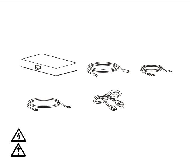
Inventory
Safety
Electrical Hazard: For indoor use only.
•Risk of electric shock. Do not plug into another relocatable power tap.
•Overloading. Do not overload the wall outlet where this device is being connected. Do not overload this device. Ensure the total load to this device does not exceed that which is listed in the Specifications section of this manual.
•Power. Ensure this device is connected to a properly grounded utility power source. Further ensure the device is plugged into a source providing the required 120 Vac. Do not use a plug adapter that defeats the ground pin on the utility power plug.
•Placement. Do not install this device on any unsteady surface. Do not install this device on any heat source.
•Water and Moisture. Do not use this product near any source of water, or in an environment where the relative humidity may exceed 95% (non-condensing)
•Polarization. This device has a polarized utility line plug having one grounding pin. This plug will only fit into the wall outlet in one orientation. This is a safety feature. Do not remove the round grounding pin.
•System Ground Terminal. The unit provides for the connection of grounding wires from all of your equipment to a central terminal lug. This ground connection eliminates ground loop problems; tie all component grounds to this screw to break any possible ground loops that can cause an audible noise.
•Servicing. There are no user-serviceable components within this device. Removal of the rear cover of this device may present a shock hazard, and/or void the warranty.
•Damage Requiring Service. If any type of damage occurs to this device, immediately disconnect it from the wall outlet. Notify APC Technical Support or Customer Service at once.
A/V J Type Power Conditioner and Battery Backup |
1 |
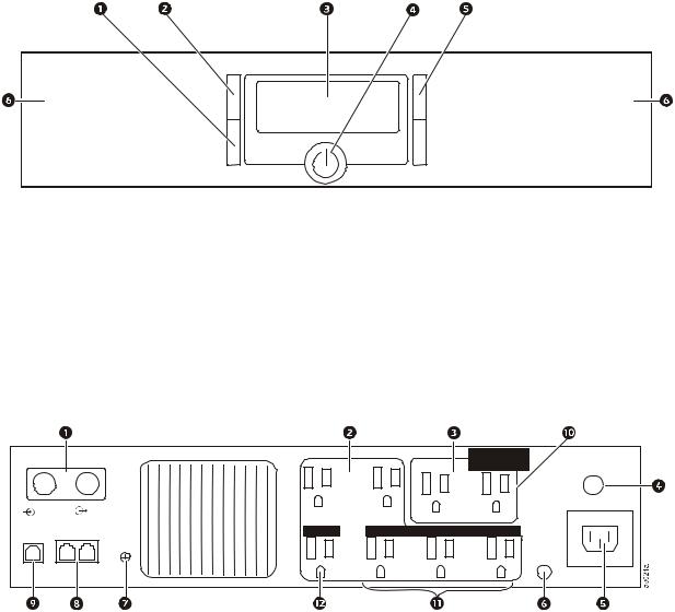
Product Overview
Front panel
av022a
1SETUP button - Push to scroll through the Setup menu screens. Press and hold for three seconds to save the current screen as the default screen.
2STATUS button - Push to scroll through the menu screens. Press and hold for 10 seconds to view the Diagnostic menu screens.
3 LCD Display
4ON/OFF button - Push this button to apply power to the outlets. The unit will continue to provide surge protection when the unit is turned on or off.
5 UP/DOWN buttons - Use the up and down buttons to scroll through options on the menu screens.
6 Removable front bezel - The front bezel can be removed to connect the battery, or to replace the battery.
Rear panel
|
|
|
|
|
CONTROLLED |
Circuit Breaker |
|
|
|
|
|
BY MASTER |
|
|
|
|
|
|
Push to Reset |
|
|
|
|
|
|
|
|
Cable |
|
Cable |
|
Battery Backup |
Surge Only |
Input 120 V- |
In |
|
Out |
|
|
|
|
USB Tel/DVR/SAT/DSL |
TVSS |
MASTER |
CONTROLLED BY MASTER |
|
||
|
|
|
||||
|
|
|
GND |
|
|
Building |
Data Port |
In |
To |
|
|
|
Wiring Fault |
|
|
|
|
|||
|
|
Equipment |
|
|
|
|
1 Coaxial surge protected, input and output connectors
2 Battery Backup outlets with noise filtering; voltage regulation is available on the J35B model 3 Surge Protection outlets with noise filtering
4 Circuit breaker reset button
5 120 Vac input outlet, use with the supplied input power cord 6 Building wiring fault LED See “Troubleshooting” on page 9.
7TVSS ground screw. Use a wire to connect any ungrounded component to this screw. Connecting to the TVSS screw will prevent sound or video interference from ungrounded equipment.
8 Telephone line surge protection, input and output connectors
9USB port for use with optional PowerChute® Personal Edition software, available as a free download at www.apc.com. In the event of a power outage, this software will save files and gracefully shut down the computer. Use the supplied USB cable to connect the UPS to the home computer.
: Surge Protection, Controlled by Master outlet, J35B models only.
; Controlled by Master outlets with Battery Backup, J35B models only. < Master outlet, J35B models only.
2 |
A/V J Type Power Conditioner and Battery Backup |
Installation
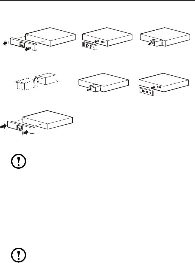
Connect Battery
1 |
2 |
|
3 |
|
av023a |
av025a |
av025a |
4 |
5 |
|
6 |
|
bu059a |
av026a |
av027a |
7 |
|
|
|
|
av028a |
|
|
Connect Input Power
Note: If the unit is connected to input power and is OFF, it will still provide protection from power surges and spikes.
Use the input power cord to connect the unit to input power. If the unit is functioning properly, the display will illuminate. Connect the other end to a grounded, 120 Vac receptacle.
Connect Equipment
Battery Backup outlets
Connect equipment to the outlets on the rear panel of the unit.
•Battery backup outlets—connect equipment that requires power during a power outage to these outlets, such as a computer or DVR.
•Surge Protection only outlets—connect noncritical equipment to these outlets, as these outlets will not have power during a power outage. The outlets continue to provide surge protection, even if the unit if OFF.
Note: The number of components plugged into the battery backup outlets will determine the battery run time. The more components that draw power from the battery backup outlets during a power outage, the less battery backup time the unit will be able to provide.
A/V J Type Power Conditioner and Battery Backup |
3 |
Power-Saving Master and Controlled outlets (J35 models only)
When the power-saving feature is enabled, the J35B reduces power consumption by automatically disconnecting utility power to devices that are not in use.
When the device connected to the Master outlet goes into sleep or standby mode, the J35B will disconnect power to components connected to the Controlled by Master outlets, conserving energy.
For example, if a desktop computer is connected to the Master outlet, when the computer goes into sleep mode, the J35B will disconnect power to peripheral devices such as a monitor, printer, and speakers that are connected to the Controlled by Master outlets.
Before connecting components to the unit, determine which components will utilize the Master and Controlled by Master outlets.
•Connect a master device such as a TV to the Master outlet.
•Connect peripheral devices such as amplifiers, DVD players, or sub-woofers to the Controlled by Master outlets.
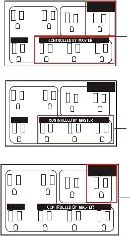
The Controlled by Master outlets can be enabled in three ways. This provides multiple outlet configuration options.
On A configuration enables all of the Controlled by the Master outlets.
CONTROLLED
BY MASTER
Battery Backup |
Surge Only |
On A
MASTER
av042a
On B configuration enables the Battery Backup outlets to be controlled by the Master outlet.
CONTROLLED
BY MASTER
Battery Backup |
Surge Only |
MASTER
On B
av043a
On S configuration enables the Surge Only outlets to be controlled by the Master outlet.
CONTROLLED
BY MASTER
Battery Backup |
Surge Only |
On S |
|
|
MASTER
av041a
Connect components to the outlets on the rear panel of the unit.
4 |
A/V J Type Power Conditioner and Battery Backup |
Operation
Display Interface Menus
Start up menu screens
At initial start up, the LCD screen will scroll through several menu screens and perform a self test.
APC - Legendary
Reliability
J35 PWR CONDITNR
WITH BATT BACKUP
SELF TEST ON....
ON-LINE TEST
SELF TEST ON....
ON-BATTERY TEST
SELF TEST RSLT:
TEST HAS PASSED
Status menu
The Status menu shows the overall status of the unit and of each outlet on the unit. Push the STATUS button to move to the next screen. Use the arrow keys to scroll up and down.
Note: The menus shown in this manual are for reference only. Information displayed on the unit may be different than shown here.
Source of output power and estimated available run time on battery.
SOURCE: UTILITY
EST RUN T: 4MIN
The possible Source options include:
•Utility—Input power is safe and steady
•Battery—Utility input power is not available or is at an unsafe level, the unit is supplying power from the batteries
•Vac Boost—Utility input power is too low, the unit is increasing power to a safe level (J35B models only)
•Vac Trim—Utility input power is too high, the unit is decreasing power to a safe level (J35B models only)
A/V J Type Power Conditioner and Battery Backup |
5 |
Estimate run time and current battery charge. As the battery charge increases, the battery run time will also increase.
EST RUN T: 4 MIN 50%
System load. The system load indicates how much power is being used by the connect equipment. The percentage indicates the amount of the unit capacity currently being used.
SYS LOAD: 900W 90%
Input and output voltage.
INPUT VOLT: 120V
OUTPUT VOLT: 120V
INPUT Hz: 60Hz
OUTPUT Hz: 60Hz
Model number and firmware.
MDL#: J35B AV UPS
FW VER: 874.P0.D
Serial number.
SN#:
JB02008004444
Service contact information.
SERVICE TEL#: 1-888-882-7228
Web support information.
WEB:WWW.APC.COM/
SUPPORT
Setup menu
Use the Setup menus to configure the unit. There are nine setup menus. Push the SETUP button to move to the next screen. Use the arrow keys to scroll up and down.
Note: The menus shown in this manual are for reference only. Information displayed on the unit may be different than shown here.
6 |
A/V J Type Power Conditioner and Battery Backup |
Audio alarm. Change the alarm setting to on or off. The unit will emit an audible beep if there is a fault or if the unit changes to operate on battery, has a low battery condition, or is overloaded.
AUDIO ALARM: OFF
PRESS 
 TO CHNG
Sensitivity. Select Low, Medium, or High to determine how often the until will switch to battery power. If the sensitivity it set to Low, the unit will tolerate more fluctuations in power, and will switch to battery less often. If the sensitivity is set to High, the unit will switch to battery power more often.
SENSITIVITY: MED
PRESS
 TO CHNG
Display dimmer. Change the brightness of the LCD display. Select Off for the display to completely darken when not in use. Push any button on the unit to illuminate the display.
DISPLAY DIM: ON
PRESS
 TO CHNG
Voltage transfer point. Set the value of the input utility voltage at which the unit will switch to battery power.
TO BAT IF < 88V
PRESS
 TO CHNG
Green function. Enable or disable the power-saving Master and Controlled outlets. See “Power-Saving Master and Controlled outlets (J35 models only)” on page 4.
GREEN FUNC: ON A
PRESS
 TO CHNG
GREEN FUNC: ON B
PRESS
 TO CHNG
GREEN FUNC: ON S
PRESS
 TO CHNG
A/V J Type Power Conditioner and Battery Backup |
7 |

Green function - transfer threshold. Configure the master outlet to recognize when the master device has gone into sleep or standby mode. Configure the delay between when the Master unit turns off and the peripheral units turn off.
MASTER THRES: 25W
PRESS
 TO CHNG
CON ONDLY: 4 SEC
PRESS
 TO CHNG
CON OFFDLY: 4 SEC-
PRESS
 TO CHNG
Low battery warning. Set the time at which the unit will provide an audible warning that it almost exhausted battery power.
LOWBATTWARN: 2MIN
PRESS
 TO CHNG
Suggested battery replacement date. The Repdate shows the date on which the battery was last replaced. Update this date if a new battery pack is installed.
REPDATE: 3/04/12
PRESS 
 TO CHNG
Self-test. Select yes to initiate a self-test of the unit. If the test fails, contact APC technical support.
DO SELFTEST: NO
PRESS 
 TO CHNG
Runtime calibration. Perform a runtime calibration test to completely discharge the batteries, and recharge them. This allows the unit to accurately predict runtime capacity. This test should be run once a year, after the unit has been in service for at least one year.
RUNTIME CAL: NO
PRESS 
 TO CHNG
LED and audible alarms test. Perform this test to test the LEDs and the audible alarms on the unit.
DSPLY-BP TEST: NO
PRESS 
 TO CHNG
Screen saver. Turn the screen saver on or off.
SCREEN SAVER: ON
PRESS 
 TO CHNG
Reset to factory defaults. Reset all settings to the factory default.
RESET->DEFLT: NO
PRESS 
 TO CHNG
8 |
A/V J Type Power Conditioner and Battery Backup |

Troubleshooting
Problem |
Possible Cause |
Corrective Action |
|
|
|
The unit will not turn on. |
The unit is not connected to utility power. |
Ensure that the unit is securely connected to |
|
|
a utility power outlet. |
|
|
|
|
The internal battery is not connected. |
Connect the battery. |
The unit does not provide |
Ensure that essential equipment is not |
Disconnect equipment from the SURGE |
power during a utility power |
plugged into a SURGE ONLY outlet. |
ONLY outlet and re-connect to a Battery |
outage. |
|
Backup outlet. |
|
|
|
The unit is operating on |
The plug has partially pulled out of the |
Ensure that the plug is fully inserted into |
battery power, while connected |
wall outlet, the wall outlet is no longer |
the wall outlet. Ensure that the wall outlet is |
to utility power. |
receiving utility power, or the circuit |
receiving utility power by checking it with |
|
breaker has been tripped. |
another device. |
|
|
|
|
The unit is performing an automatic self |
No action is necessary. |
|
test. |
|
The utility input voltage is out of range, the frequency is out of range, or the waveform is distorted.
Adjust the transfer voltage and sensitivity range.
The circuit breaker has been tripped.
Disconnect non-essential equipment from the unit. Reset the circuit breaker. Reconnect equipment one item at a time. If the circuit breaker is tripped again, disconnect the device that caused the trip.
The unit does not provide the expected amount of backup time.
Battery Backup outlets may be fully or |
Disconnect non-essential equipment from |
improperly loaded. |
the Battery Backup outlets and connect the |
|
equipment to SURGE ONLY outlets. |
|
|
The battery was recently discharged due |
Charge the battery cartridge for 16 hours. |
to a power outage and has not fully |
|
recharged. |
|
|
|
The battery has reached the end of its |
Replace the battery. |
useful life. |
|
Power is not supplied to some outlets.
Power to the Controlled outlets has intentionally been turned off.
Confirm that the correct peripherals are connected to Controlled outlets. If this feature is not desired, disable the PowerSaving Master and Controlled outlets.
The Controlled outlets are not supplying power, even though the Master device is not in sleep mode.
The Master Outlet threshold may be incorrectly set.
Adjust the threshold when the Master outlet signals the Controlled outlets to shut down.
A/V J Type Power Conditioner and Battery Backup |
9 |
Loading...