


 Loading...
DOC. NO.: MX4LS-OL-E0208B
1
Online Manual
|
Overview |
|
|
|
|
Installation |
Hardware |
|
|
|
|
& Drivers Utilities |
|
|
|
|
|
AWARD Setup BIOS |
|
|
|
|
|
|
Glossary |
|
|
|
|
Support Technical |
& Troubleshooting |
|
|

|
Online Manual |
What’s in this manual |
|
MX4LS ............................................................................................................................................. |
1 |
What’s in this manual ...................................................................................................................................................... |
2 |
You Must Notice .............................................................................................................................................................. |
8 |
Before You Start .............................................................................................................................................................. |
9 |
Overview ....................................................................................................................................................................... |
10 |
Feature Highlight........................................................................................................................................................... |
11 |
Quick Installation Procedure ......................................................................................................................................... |
15 |
Motherboard Map .......................................................................................................................................................... |
16 |
Block Diagram............................................................................................................................................................... |
17 |
Hardware Installation.................................................................................................................. |
18 |
About “User Upgrade Optional” and “Manufacture Upgrade Optional”… ....................................................................... |
19 |
JP14 Clear CMOS Data ................................................................................................................................................ |
20 |
CPU Installation ............................................................................................................................................................ |
21 |
CPU Jumper-less Design .............................................................................................................................................. |
24 |
Full-range Adjustable CPU Core Voltage....................................................................................................................... |
26 |
CPU and System Fan Connector (with H/W Monitoring) ............................................................................................... |
28 |
JP28 Keyboard/Mouse Wake-up Enable/Disable Jumper.............................................................................................. |
29 |
2

|
Online Manual |
DIMM Sockets support PC100/133................................................................................................................................ |
30 |
Front Panel Connector .................................................................................................................................................. |
32 |
ATX Power Connector ................................................................................................................................................... |
33 |
AC Power Auto Recovery .............................................................................................................................................. |
34 |
STBY LED and BOOT LED ........................................................................................................................................... |
35 |
IDE and Floppy Connector ............................................................................................................................................ |
36 |
IrDA Connector ............................................................................................................................................................. |
38 |
S/PDIF (Sony/Philips Digital Interface) Connector......................................................................................................... |
39 |
ADD (AGP Digital Display) Slot ..................................................................................................................................... |
40 |
CNR (Communication and Network Riser) Expansion Slot............................................................................................ |
41 |
PC99 Color Coded Back Panel ..................................................................................................................................... |
42 |
Support 10/100 Mbps LAN Onboard.............................................................................................................................. |
43 |
Support 2nd and 3rd USB2.0 Ports.................................................................................................................................. |
44 |
Case Open Connector................................................................................................................................................... |
45 |
WOL (Wake on LAN)..................................................................................................................................................... |
46 |
CD Audio Connector ..................................................................................................................................................... |
47 |
AUX-IN Connector ........................................................................................................................................................ |
48 |
Front Audio Connector .................................................................................................................................................. |
49 |
COM2 Connector .......................................................................................................................................................... |
50 |
3

|
Online Manual |
Battery-less and Long Life Design ................................................................................................................................ |
51 |
CPU Over-current Protection......................................................................................................................................... |
52 |
Hardware Monitoring ..................................................................................................................................................... |
53 |
Resetable Fuse ............................................................................................................................................................. |
54 |
3300µF Low ESR Capacitor .......................................................................................................................................... |
55 |
Enlarged Aluminum Heatsink ........................................................................................................................................ |
56 |
Open JukeBox Player.................................................................................................................................................... |
57 |
Vivid BIOS technology................................................................................................................................................... |
61 |
Driver and Utility ......................................................................................................................... |
62 |
Auto-run Menu from Bonus CD ..................................................................................................................................... |
63 |
Installing Intel® Chipset Software Installation Utility...................................................................................................... |
64 |
Installing Intel 845GL VGA driver .................................................................................................................................. |
65 |
Installing Intel IAA Driver............................................................................................................................................... |
66 |
Installing Onboard Audio Driver..................................................................................................................................... |
67 |
Installing LAN Driver ..................................................................................................................................................... |
68 |
Installing USB2.0 Driver ................................................................................................................................................ |
69 |
AOConfig Utility............................................................................................................................................................. |
72 |
Installing Hardware Monitoring Utility ............................................................................................................................ |
74 |
Phoenix-AWARD BIOS.................................................................................................................. |
75 |
4

|
Online Manual |
About BIOS Function Description… .............................................................................................................................. |
76 |
How To Use Award™ BIOS Setup Program .................................................................................................................. |
77 |
How To Enter BIOS Setup ............................................................................................................................................. |
79 |
BIOS Upgrade under Windows environment ................................................................................................................. |
80 |
Glossary ....................................................................................................................................... |
82 |
AC97 ............................................................................................................................................................................. |
82 |
ACPI (Advanced Configuration & Power Interface) ....................................................................................................... |
82 |
AGP (Accelerated Graphic Port) ................................................................................................................................... |
82 |
AMR (Audio/Modem Riser)............................................................................................................................................ |
83 |
AOpen Bonus Pack CD ................................................................................................................................................. |
83 |
APM (Advanced Power Management)........................................................................................................................... |
83 |
ATA (AT Attachment) ..................................................................................................................................................... |
83 |
ATA/66 .......................................................................................................................................................................... |
83 |
ATA/100 ........................................................................................................................................................................ |
84 |
ATA/133 ........................................................................................................................................................................ |
84 |
BIOS (Basic Input/Output System) ................................................................................................................................ |
84 |
Bus Master IDE (DMA mode) ........................................................................................................................................ |
85 |
CNR (Communication and Networking Riser)................................................................................................................ |
85 |
CODEC (Coding and Decoding).................................................................................................................................... |
85 |
5

|
Online Manual |
DDR (Double Data Rated) SDRAM ............................................................................................................................... |
85 |
DIMM (Dual In Line Memory Module) ............................................................................................................................ |
86 |
DMA (Direct Memory Access)........................................................................................................................................ |
86 |
ECC (Error Checking and Correction) ........................................................................................................................... |
86 |
EDO (Extended Data Output) Memory .......................................................................................................................... |
86 |
EEPROM (Electronic Erasable Programmable ROM).................................................................................................... |
87 |
EPROM (Erasable Programmable ROM) ...................................................................................................................... |
87 |
EV6 Bus ........................................................................................................................................................................ |
87 |
FCC DoC (Declaration of Conformity) ........................................................................................................................... |
87 |
FC-PGA (Flip Chip-Pin Grid Array)................................................................................................................................ |
88 |
Flash ROM .................................................................................................................................................................... |
88 |
FSB (Front Side Bus) Clock .......................................................................................................................................... |
88 |
I2C Bus.......................................................................................................................................................................... |
88 |
IEEE 1394..................................................................................................................................................................... |
89 |
Parity Bit ....................................................................................................................................................................... |
89 |
PBSRAM (Pipelined Burst SRAM)................................................................................................................................. |
89 |
PC-100 DIMM ............................................................................................................................................................... |
90 |
PC-133 DIMM ............................................................................................................................................................... |
90 |
PC-1600 or PC-2100 DDR DRAM ................................................................................................................................. |
90 |
6

|
Online Manual |
PCI (Peripheral Component Interface) Bus |
................................................................................................................... 90 |
PDF Format................................................................................................................................................................... |
90 |
PnP (Plug and Play) ...................................................................................................................................................... |
91 |
POST (Power-On Self Test) .......................................................................................................................................... |
91 |
RDRAM (Rambus DRAM) ............................................................................................................................................. |
91 |
RIMM (Rambus Inline Memory Module) ........................................................................................................................ |
91 |
SDRAM (Synchronous DRAM) ...................................................................................................................................... |
92 |
Shadow E2PROM .......................................................................................................................................................... |
92 |
SIMM (Single In Line Memory Module) ......................................................................................................................... |
92 |
SMBus (System Management Bus)............................................................................................................................... |
92 |
SPD (Serial Presence Detect) ....................................................................................................................................... |
93 |
Ultra DMA ..................................................................................................................................................................... |
93 |
USB (Universal Serial Bus) ........................................................................................................................................... |
93 |
VCM (Virtual Channel Memory)..................................................................................................................................... |
94 |
ZIP file........................................................................................................................................................................... |
94 |
Troubleshooting........................................................................................................................... |
95 |
Technical Support ....................................................................................................................... |
99 |
Product Registration ................................................................................................................. |
102 |
How to Contact Us .................................................................................................................... |
103 |
7

Online Manual
You Must Notice
Adobe, the Adobe logo, Acrobat is trademarks of Adobe Systems Incorporated.
AMD, the AMD logo, Athlon and Duron are trademarks of Advanced Micro Devices, Inc.
Intel, the Intel logo, Intel Celeron, Pentium II, Pentium III and Pentium 4 are trademarks of Intel Corporation.
Microsoft, Windows, and Windows logo are either registered trademarks or trademarks of Microsoft Corporation in the United States and/or other countries.
All product and brand names used on this manual are used for identification purposes only and may be the registered trademarks of their respective owners.
All of the specifications and information contained in this manual are subject to change without notice. AOpen reserves the right to revise this publication and to make reasonable changes. AOpen assumes no responsibility for any errors or inaccuracies that may appear in this manual, including the products and software described in it.
This documentation is protected by copyright law. All rights are reserved.
No part of this document may be used or reproduced in any form or by any means, or stored in a database or retrieval system without prior written permission from AOpen Corporation.
Copyright© 1996-2002, AOpen Inc. All Rights Reserved.
8

Online Manual
Before You Start
This Online Manual will introduce to the user how this product is installed. All useful information will be described in later chapters. Please keep this manual carefully for future upgrades or system configuration changes. This Online Manual is saved in PDF format, we recommend using Adobe Acrobat Reader 4.0 for online viewing, it is included in Bonus CD or you can get free download from Adobe web site.
Although this Online Manual is optimized for screen viewing, it is still capable for hardcopy printing, you can print it by A4 paper size and set 2 pages per A4 sheet on your printer. To do so, choose File > Page Setup and follow the instruction of your printer driver.
Thanks for the help of saving our earth.
9
Online Manual
Overview
Thank you for choosing AOpen MX4LS motherboard. MX4LS is Intel® Socket 478 motherboard (M/B) based on the Micro-ATX form factor featuring the Intel® 845GL(Brookdale) chipset. As high performance chipset built in the M/B, MX4LS motherboard support Intel® Socket 478 Pentium® 4 (Brookdale) and 400 MHz Front Side Bus (FSB) clock. On the strength of Intel 845GL chipset, this motherboard multiplexes the AGP signal interface with two Intel DVO ports that are capable of supporting a variety of digital display devices such as TV-Out encoders. According to different customer’s requirements, the Intel 845GL chipset memory interface supports PC100/133 SDRAM devices with densities of 64, 128, 256, 512MB or 1GB SDRAM DIMM modules and the maximum memory size can be up to 2 GB. The onboard IDE controller supports Ultra DMA 33/66/100 mode and the transfer rate up to 100MB/s. Further flexibility can be achieved by taking
advantage of the Communication and Network Riser (CNR) card option that allows audio and modem configuration on a single baseboard design. Besides, the MX4LS has an AC97 CODEC  chipset onboard, providing high performance and magic
  surround stereo sound to let people enjoy working with it. Now,
let’s enjoy all features from AOpen MX4LS motherboard.
10
Online Manual
Feature Highlight
CPU
Supports Intel® Socket 478 Pentium® 4 (Brookdale) 1.4GHz~2.4GHz+ with 400MHz Front Side Bus (FSB) designed for Socket 478 technology.
Chipset
With Intel® 845GL (Brookdale) chipset, Intel delivers a discrete graphics solution with all the performance, innovative features and proven reliability of the Intel® 845GL chipset. With its highly scalable design, the new 845GL chipset offers an ideal, multiplexed Intel DVO Port for Intel® Pentium® 4 processor platforms. And the smart integration in the Intel 845GL chipset's I/O Controller Hub (ICH4) features USB controllers supporting six USB2.0 ports. With support for AC’97 audio and the ability to make the most of soft audio/modem technology, the 845GL chipset delivers an ideal solution for innovative new form factors.
Expansion Slots
Including three 32-bit/33MHz PCI, one CNR and one multiplexed Intel DVO Port. The PCI local bus throughput can be up to 132MB/s. The Communication & Nectworking Riser (CNR) slot provided from MX4LS support CNR interface for a Modem/Audio card. The multiplexed Intel DVO Port specification provides a new level of video display sophistication and speed which supports DVI/TV-Out add-on card. Of three PCI slots provided, all of them are master PCI slots with arbitration and decoding for all integrated functions and LPC bus.
11

Online Manual
Memory
Provides two 168-pin SDRAM DIMM sockets that support up to 2GB of PC-100/133 compliant SDRAM (Synchronous Dynamic Random Access Memory). You may install 64, 128, 256, 512MB or 1GB SDRAM DIMM modules into each socket.
Ultra DMA 33/66/100 Bus Master IDE
Comes with an on-board PCI Bus Master IDE controller with two connectors that supports four IDE devices in two channels, supports Ultra DMA 33/66/100, PIO Modes 3 and 4 and Bus Master IDE DMA Mode 5, and supports Enhanced IDE devices.
On-board AC’97 Sound
MX4LS uses the AC97 sound chip. This on-board audio includes a complete audio recording and playback system.
1MHz Stepping Frequency Adjustment
Provides “1MHz Stepping Frequency Adjustment” function in the BIOS. This magic function allows you to adjust FSB frequency from 100~248 by 1MHz stepping adjustment, and helps your system get maximum performance.
Watch Dog Timer
Includes AOpen “Watch Dog Timer” function that can auto-reset default settings in 4.8 seconds when you fail system overclocking.
12

Online Manual
S/PDIF Connectors
S/PDIF (Sony/Philips Digital Interface) is the newest audio transfer file format, which provides impressive quality through optical fiber and allows you to enjoy digital audio instead of analog audio.
Six USB2.0 Connectors
Provides three ports, six USB connectors for USB interface devices, such as mouse, keyboard, modem, scanner, etc.
Power Management/Plug and Play
Supports the power management function that confirms to the power-saving standards of the U.S. Environmental Protection Agency (EPA) Energy Star program. It also offers Plug-and-Play, which helps save users from configuration problems, thus making the system much user-friendlier.
Hardware Monitoring Management
Supports CPU or system fans status, temperature and voltage monitoring and alert, through the on-board hardware monitor module.
Enhanced ACPI
Fully implement the ACPI standard for Windows® 98/ME/2000 series compatibility, and supports Soft-Off, STR (Suspend to RAM, S3), STD (Suspend to Disk, S4) features.
13

Online Manual
Super Multi-I/O
Provides two high-speed UART compatible serial ports and one parallel port with EPP and ECP capabilities. UART can also be directed from COM1 to the Infrared Module for the wireless connections.
14

Online Manual
Quick Installation Procedure
This page gives you a quick procedure on how to install your system. Follow each step accordingly.
1.Installing CPU and Fan
2.Installing System Memory (DIMM)
3.Connecting Front Panel Cable
4.Connecting IDE and Floppy Cable
5.Connecting ATX Power Cable
6.Connecting Back Panel Cable
7.Power-on and Load BIOS Setup Default
8.Setting CPU Frequency
9.Reboot
10.Installing Operating System (such as Windows 98)
11.Installing Driver and Utility
15

Online Manual
Motherboard Map
|
CD-IN Connector |
|
|
|
|
|
|
|
|
|
|
|
|
|
|
|
|
|
|
|
|
|
|
|
|
|
|
|
|
|
|
||||||
|
SPDIF Connector |
|
|
|
|
|
|
|
|
|
|
|
|
|
|
|
|
|
|
|
|
|
|
|
|
|
PC99 Colored Back Panel |
||||||||||
|
Onboard AC’97 CODEC |
|
|
|
|
|
|
|
|
|
|
|
|
|
|
|
|
|
|
|
|
|
|
|
|
|
|
|
|
|
|
|
|
|
|||
|
|
|
|
|
|
|
|
|
|
|
|
|
|
|
|
|
|
|
|
|
|
|
|
|
|
|
|
|
|
|
|
|
|
||||
|
|
|
|
|
|
|
|
|
|
|
|
|
|
|
|
|
|
|
|
|
|
|
|
|
|
|
|
||||||||||
|
|
|
|
|
|
|
|
|
|
|
|
|
|
|
|
|
|
|
|
|
|
|
|
|
|
|
|||||||||||
|
AUX-IN Connector |
|
|
|
|
|
|
|
|
|
|
|
|
|
|
|
|
|
|
|
|
|
|
|
|
|
COM2 Connector |
||||||||||
|
|
|
|
|
|
|
|
|
|
|
|
|
|
|
|
|
|
|
|
|
|
|
|
||||||||||||||
|
|
|
|
|
|
|
|
|
|
|
|
|
|
|
|
|
|
|
|
|
|
|
|
|
|
||||||||||||
|
|
|
|
|
|
|
|
|
|
|
|
|
|
|
|
|
|
|
|
|
|
|
|
|
|
|
|
|
|
|
|
|
|
|
|
||
|
CNR Expansion Slot |
|
|
|
|
|
|
|
|
|
|
|
|
|
|
|
|
|
|
|
|
|
|
|
|
|
|
|
|
|
|
|
JP28 Mouse/Keyboard Wakeup |
||||
|
|
|
|
|
|
|
|
|
|
|
|
|
|
|
|
|
|
|
|
|
|
|
|
|
|
|
|
|
|||||||||
|
|
|
|
|
|
|
|
|
|
|
|
|
|
|
|
|
|
|
|
|
|
|
|
|
|||||||||||||
|
|
|
|
|
|
|
|
|
|
|
|
|
|
|
|
|
|
|
|
|
|
|
|
|
|
|
|
|
|
|
|
|
|
|
|
Jumper |
|
|
|
|
|
|
|
|
|
|
|
|
|
|
|
|
|
|
|
|
|
|
|
|
|
|
|
|
|
|
|
|
|
|
|
|
|
4-pin 12V. ATX Power Connector |
|
|
|
|
|
|
|
|
|
|
|
|
|
|
|
|
|
|
|
|
|
|
|
|
|
|
|
|
|
|
|
|
|
|
|
|
|
||
|
|
|
|
|
|
|
|
|
|
|
|
|
|
|
|
|
|
|
|
|
|
|
|
|
|
|
|
|
|
|
|
|
|
|
|
||
|
|
|
|
|
|
|
|
|
|
|
|
|
|
|
|
|
|
|
|
|
|
|
|
|
|
|
|
|
|
|
|
|
|
|
|
3300μF Low ESR Capacitors |
|
32-bit PCI Expansion Slot x3 |
|
|
|
|
|
|
|
|
|
|
|
|
|
|
|
|
|
|
|
|
|
|
|
|
ADD Slot (for ADD card only) |
||||||||||||
|
Case Open Connector |
|
|
|
|
|
|
|
|
|
|
|
|
|
|
|
|
|
|
|
|
|
|
|
|
|
|
|
|
|
|
|
|
|
|
478-pin CPU socket with Voltage |
|
|
|
|
|
|
|
|
|
|
|
|
|
|
|
|
|
|
|
|
|
|
|
|
|
|
|
|
|
|
|||||||||
|
WOL Connector |
|
|
|
|
|
|
|
|
|
|
|
|
|
|
|
|
|
|
|
|
|
|
|
|
|
|
|
and Frequency Auto-detection that |
||||||||
|
|
|
|
|
|
|
|
|
|
|
|
|
|
|
|
|
|
|
|
|
|
|
|
|
|
|
|
|
|
|
|
|
|
|
|
supports Intel® Pentium® 4 |
|
|
|
|
|
|
|
|
|
|
|
|
|
|
|
|
|
|
|
|
|
|
|
|
|
|
|
|
|
|
|
|
|
|
|
|
|||
|
|
|
|
|
|
|
|
|
|
|
|
|
|
|
|
|
|
|
|
|
|
|
|
|
|
|
|
|
|
|
|
|
|
|
|
1.4~2.4GHz+ CPU |
|
|
Front Audio Connector |
|
|
|
|
|
|
|
|
|
|
|
|
|
|
|
|
|
|
|
|
|
|
|
|
|
|
|
|
Intel 845GL chipset |
|||||||
|
|
|
|
|
|
|
|
|
|
|
|
|
|
|
|
|
|
|
|
|
|
|
|
|
|
|
|
||||||||||
|
2nd & 3rd USB Connector |
|
|
|
|
|
|
|
|
|
|
|
|
|
|
|
|
|
|
|
|
|
|
|
|
|
|
SYSFAN2 Connector |
|||||||||
|
|
|
|
|
|
|
|
|
|
|
|
|
|
|
|
|
|
|
|
|
|
|
|
|
|
||||||||||||
|
|
|
|
|
|
|
|
|
|
|
|
|
|
|
|
|
|
|
|
|
|
|
|
168-pin DIMMx2 supports |
|||||||||||||
|
|
|
|
|
|
|
|
|
|
|
|
|
|
|
|
|
|
|
|
|
|
|
|
|
|
|
|
|
|
|
|
|
|
|
|
||
|
IrDA Connector |
|
|
|
|
|
|
|
|
|
|
|
|
|
|
|
|
|
|
|
|
|
|
||||||||||||||
|
|
|
|
|
|
|
|
|
|
|
|
|
|
|
|
|
|
|
|
|
|
|
|
PC100/133 SDRAM (Max. |
|||||||||||||
|
SYSFAN3 Connector |
|
|
|
|
|
|
|
|
|
|
|
|
|
|
|
|
|
|
|
|
|
|
|
|||||||||||||
JP14 CMOS Clear Jumper |
|
|
|
|
|
|
|
|
|
|
|
|
|
|
|
|
|
|
|
|
|
|
|
to 2GB) |
|||||||||||||
|
|
|
|
|
|
|
|
|
|
|
|
|
|
|
|
|
|
|
|
||||||||||||||||||
|
Front Panel Connector |
|
|
|
|
|
|
|
|
|
|
|
|
|
|
|
|
|
|
|
|
|
|
|
CPUFan1 Connector |
||||||||||||
|
|
|
|
|
|
|
|
|
|
|
|
|
|
|
|
|
|
|
|
|
|
|
|||||||||||||||
|
|
|
|
|
|
|
|
|
|
|
|
|
|
|
|
|
|
|
|
|
|
|
|
|
|
||||||||||||
|
4Mbit Flash ROM BIOS |
|
|
|
|
|
|
|
|
|
|
|
|
|
|
|
|
|
|
|
|
|
|
|
|
|
|
ATX Power Connector |
|||||||||
|
|
|
|
|
|
|
|
|
|
|
|
|
|
|
|
|
|
|
|
|
|
|
|
|
|
||||||||||||
|
|
|
|
|
|
|
|
|
|
|
|
|
|
|
|
|
|
|
|
|
|
|
|
|
|
|
|
|
|
|
|
|
|
|
|||
|
|
|
|
|
|
|
|
|
|
|
|
|
|
|
|
|
|
|
|
|
|
|
|
|
|
|
|
|
|
|
|
|
|
|
|
FDD Connector |
|
|
|
|
|
|
|
|
|
|
|
|
|
|
|
|
|
|
|
|
|
|
|
|
|
|
|
|
|
|
|
|
|
|
|
|
|
||
|
|
|
|
|
|
|
|
|
|
|
|
|
|
|
|
|
|
|
|
|
|
|
|
|
|
|
|
|
|
|
|
|
|
|
|
||
|
|
|
|
|
|
|
|
|
|
|
|
|
|
|
|
|
|
|
|
|
|
|
|
|
|
|
|
|
|
|
|
|
|
|
|
ATA/33/66/100 |
|
|
|
|
|
|
|
|
|
|
|
|
|
|
16 |
|
|
|
|
|
|
|
|
|
|
|
IDE Connector x2 |
|
|||||||||||
|
|
|
|
|
|
|
|
|
|
|
|
|
|
|
|
|
|
|
|
|
|
|
|
|
|
||||||||||||
Online Manual
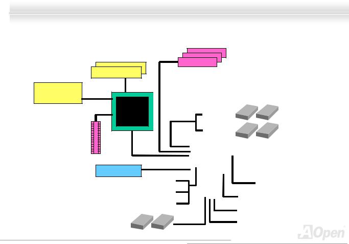
Block Diagram
Socket 478
Intel
Pentium 4
CPU
ADD Slot
PC-100/133 DDR
SDRAM Up to 2GB
DIMM Socket x2
400MHz System
Bus
Intel 845GL
GMCH
LAN connect Component
USB2.0 Port x6
Floppy Disk Drive x2
32-bit PCI Slot x3
|
PCI Bus |
|
|
|
|
|
|
|
|
|
|
|
|
|
|
|
|
|||
|
|
|
ATA |
|
|
Primary |
|
|
|
|
|
|
|
|
|
|
|
|
||
|
33/66/100 |
|
|
Channel |
|
|
|
|
|
|
|
|
IDE Drive x4 |
|||||||
|
|
|
|
|
|
|
|
|
|
|
|
|
|
|
|
|
|
|||
|
|
|
|
|
|
|
Secondary |
|
|
|
|
|
|
|
|
|
|
|
||
|
|
|
|
|
|
|
Channel |
|
|
|
|
|
|
|
|
|
|
|
||
|
|
|
|
|
|
|
|
|
|
|
|
|
|
|
|
|
|
|
|
|
|
|
|
|
|
|
|
|
|
|
|
|
|
|
|
|
|
|
|
|
|
|
|
|
|
|
|
|
|
|
|
|
|
|
|
|
||||||
|
|
|
|
|
Intel ICH4 |
|
|
|
|
AC97 |
|
|||||||||
|
|
|
|
|
|
|
|
CODEC |
|
|||||||||||
|
|
|
|
|
|
|
|
|
|
|
|
|
|
|
|
|
|
|
|
|
|
|
|
|
|
|
|
|
|
|
|
|
|
|
|
|
|
|
|
|
|
|
|
|
|
|
|
|
|
|
|
|
|
|
|
AC Link |
||||||
|
|
|
|
|
|
|
|
|
|
|
|
|
|
|||||||
|
|
|
|
|
|
|
|
|
|
|||||||||||
|
|
|
|
|
|
|
|
|
|
|
|
|
|
|
|
CNR Slot |
|
|||
|
1st USB Port |
|
|
|
|
|
Low Pin |
|
|
Firmware Hub |
|
|||||||||
|
|
|
|
|
|
|
Count |
|
|
|
|
|||||||||
|
|
|
|
|
|
|
|
|
||||||||||||
|
2nd USB Port |
|
|
|
|
|
Super |
|
|
|
|
|
|
|
|
|
|
|
|
|
|
|
|
|
|
|
I/O |
|
|
|
|
|
4Mbit Flash EEPROM |
|
|
||||||
|
|
|
|
|
|
|
|
|
|
|
|
|
|
|
|
|
|
|
||
|
|
|
|
|
|
|
|
|
|
|
|
|
|
|
|
|
|
|
|
|
|
3rd USB Port |
|
|
|
|
|
|
|
|
|
|
|
|
|
|
|
|
|
|
|
|
|
|
|
|
|
|
|
|
|
|
|
|
|
Parallel Port |
|
|
|
|
||
|
|
|
|
|
|
|
|
|
|
|
|
|
|
|
|
|
|
|||
|
|
|
|
|
|
|
|
|
|
|
|
|
|
|
|
|
|
|
|
|
|
|
|
|
|
|
|
|
|
|
|
|
|
|
|
|
|
|
|
|
|
|
|
|
|
|
|
|
|
|
|
|
|
|
|
Serial Port x2 |
|
|
|
|
||
|
|
|
|
|
|
|
|
|
|
|
|
|
|
|
|
|
|
|
|
|
17

Online Manual
Hardware Installation
This chapter describes jumpers, connectors and hardware devices of this motherboard.

 Note: Electrostatic discharge (ESD) can damage your processor, disk drives, expansion boards, and other components. Always observe the following precautions before you install a system component.
1.Do not remove a component from its protective packaging until you are ready to install it.
2.Wear a wrist ground strap and attach it to a metal part of the system unit before handling a component. If a wrist strap is not available, maintain contact with the system unit throughout any procedure requiring ESD protection.
18

Online Manual
About “User Upgrade Optional” and “Manufacture Uppggrraaddee
Optional”…
When you read this online manual and start to assemble your computer system, you may notice that some of the functions are marked as “User Upgrade Optional” or “Manufacture Upgrade Optional”. Although all of AOpen’s motherboards have included many amazing and powerful features, sometimes not every user is familiar with these powerful features. As a result of this we define features that can be upgraded by users as “User Upgrade Optional”. You can upgrade these functions by purchasing additional devices. As for functions that cannot be upgraded by users, we define them as “Manufacture Upgrade Optional”. If need be, you can contact our local distributors or resellers to purchase “Manufacture Upgrade Optional” components, and again you are also welcome to visit our official website at www.aopen.com for detail information.
19
Online Manual
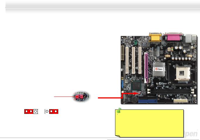
JP14 Clear CMOS Data
You can clear CMOS to restore system default setting. To clear the CMOS, follow the procedure below.
1.Turn off the system and unplug the AC power.
2.Remove ATX power cable from connector PWR2.
3.Locate JP14 and short pins 2-3 for a few seconds.
4.Return JP14 to its normal setting by shorting pin1 & pin2.
5.Connect ATX power cable back to connector PWR2.
Pin 1
1 1
Normal Clear
(default) CMOS
Tip: When should I Clear CMOS?
1.Boot fail because of overclocking…
2.Forget password…
3.Troubleshooting…
20
Online Manual
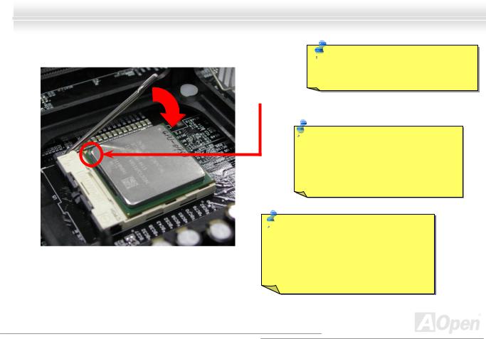
CPU Installation
This motherboard supports Intel® Pentium 4 Socket 478 series CPU (Brookdale). Be careful of CPU orientation when you plug it into CPU socket.
1.Pull up the CPU socket lever and up to 90-degree angle.
2.Locate Pin 1 in the socket and look for a cut edge on the CPU upper interface. Match Pin 1 and cut edge, then insert the CPU into the socket.
CPU socket |
CPU pin 1 and |
Lever |
cut edge |
 CPU cut edge
Note: These pictures are for example only; it may not look exactly the same with the motherboard you purchased.
21
Online Manual
3.Press down the CPU socket lever and finish CPU installation.
CPU cut edge

 Note: If you do not match the CPU socket Pin 1 and CPU cut edge well, it may damage the CPU.
Note: This socket supports Micro-FC-PGA2 package CPU, which is the latest CPU package developed by Intel. Other forms of CPU package are impossible to be fitted in.
 Note: P4 CPU tends to produce higher temperature; for better heat dissipation, we recommend you to install this motherboard with a bigger housing. Besides, by doing so you can prevent components from colliding.
Note: These pictures are for example only; it may not look exactly the same with the motherboard you purchased.
22
Online Manual
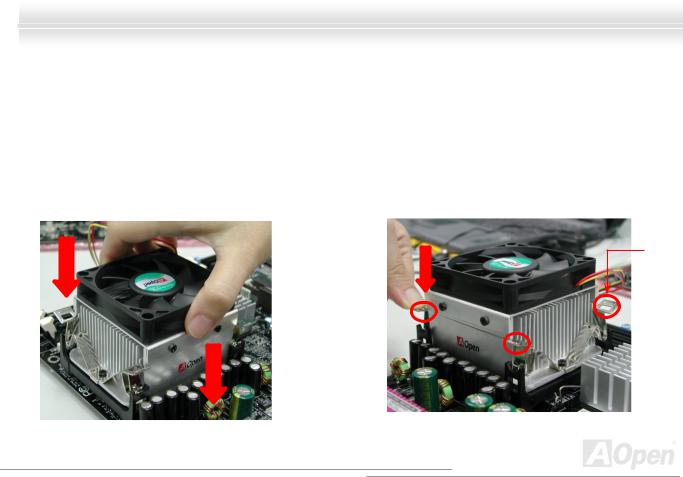
CPU Fan Installation
This motherboard comes with a retention module attached on the CPU socket when shipped, we strongly recommend you to install AOpen special designed CPU Fan as shown below on the retention module for better heat dissipation. Please install the
CPU Fan correctly as the following pictures shown.
1. Gently put the CPU Fan down on the retention module with clips aligning correctly to the four corners.
2.Pressing down the four clips with force one by one on the retention module.
Clip
23
Online Manual
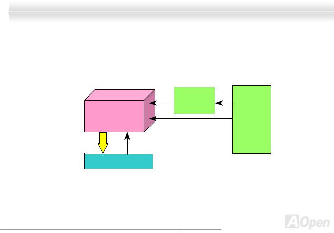
CPU Jumper-less Design
CPU VID signal and SMbus clock generator provide CPU voltage auto-detection and allows the user to set the CPU frequency through the BIOS setup, therefore no jumpers or switches are used. The disadvantages of the Pentium based jumper-less designs are eliminated. There will be no worry of wrong CPU voltage detection.
|
Clock |
|
Intel® Socket 478 |
Generator |
BIOS |
Pentium 4 CPU |
|
Controlled |
|
CPU Freq. Ratio |
Circuit |
CPU VID signal |
CPU voltage |
|
Power Regulator |
|
|
(Automatically generates CPU voltage) |
|
|
24
Online Manual
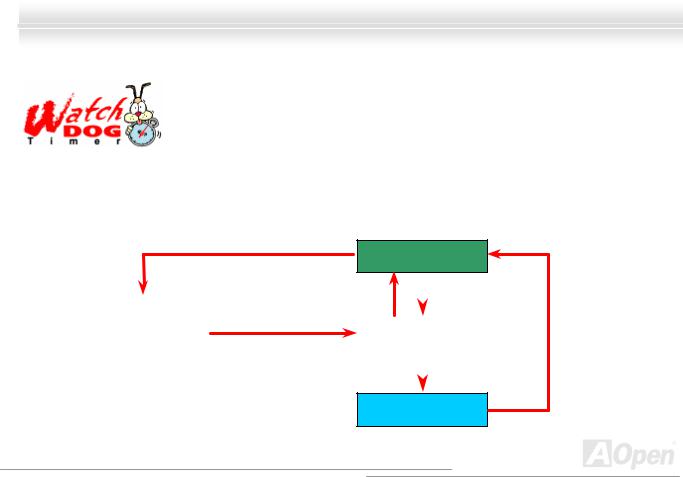
AOpen “Watch Dog Timer”
AOpen provides a special and useful feature on this motherboard for overclockers. When you power-on the system, BIOS will check last system POST status. If it succeeds, the BIOS will enable “Watch Dog Timer” function immediately, and set the CPU FSB frequency according to user’s settings stored in BIOS. If system fails in BIOS POST, then “Watch Dog Timer” will reset
the system to reboot in five seconds. BIOS will detect the CPU’s default frequency and POST again. With this special feature, you can easily overclock your system to get a higher system performance without removing the system housing and save the hassle from setting the jumper to clear CMOS data when system hangs.
Enable/Disable Signal
from BIOS
BIOS
|
Reset Signal |
|
|
|
AOpen |
|
CPU ID Signal |
||
|
|
|
||
|
Clock Generator |
|||
Watch Dog |
|
|||
Timer |
Countdown about |
|
|
|
|
|
|
||
|
5 seconds if fails |
|
|
|
|
|
|
||
|
in POST |
|
|
|
CPU
25
Online Manual
Full-range Adjustable CPU Core Voltage
This function is dedicated to overclockers and supports Adjustable CPU Core Voltage from 1.10V to 1.85V. But this motherboard can also automatically detects CPU VID signal and generates proper CPU core voltage.
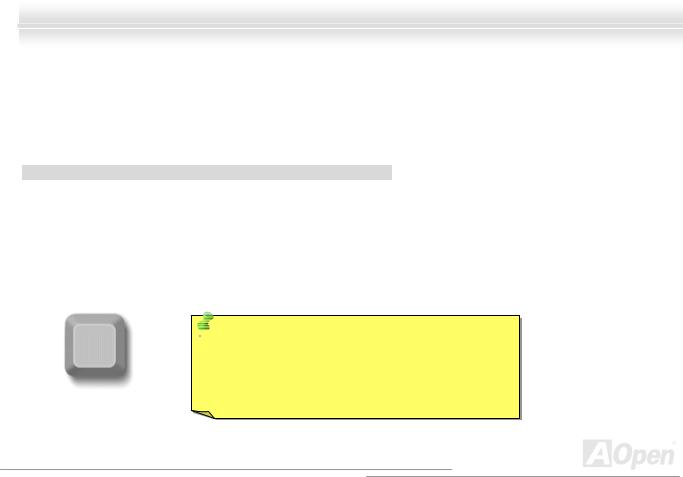
Setting CPU Frequency
BIOS Setup > Frequency/Voltage Control > CPU Clock Setting
This motherboard is CPU jumper-less design, you can set CPU frequency through the BIOS setup, and no jumpers or switches are needed.
|
CPU Ratio |
|
|
8x, 9x, 10x,…22x, 23x, 24x |
|
|
|
|
|
|
|
|
CPU FSB |
|
|
100~248MHz |
|
|
|
|
|
|
|
 Tip: If your system hangs or fails to boot because of Home overclocking, simply use <Home> key to restore the default setting or you can wait the AOpen “Watch Dog Timer” reset the system after five seconds and system
will auto-detect hardware again.
26
Online Manual
Core Frequency = CPU FSB Clock * CPU Ratio
PCI Clock = CPU FSB Clock / Clock Ratio
AGP Clock = PCI Clock x 2
|
|
|
|
|
|
|
|
|
|
|
|
|
|
|
|
|
|
|
|
|
|
|
|
|
|
|
|
|
|
|
CPU Core |
|
|
|
|
|
|
|
|
|
|
|
|
|
|
|
|
|
|
|
|
|
Northwood CPU |
FSB Clock |
|
|
|
System |
Bus |
|
|
|
Ratio |
|
|
|
|||||||||||
|
|
|
Frequency |
|
|
|
|
|
|
|
|
|
|
|
|||||||||||
|
|
|
|
|
|
|
|
|
|
|
|
|
|
|
|
|
|
|
|
|
|
|
|
|
|
|
|
|
|
|
|
|
|
|
|
|
|
|
|
|
|
|
|
|
|
|
|||||
|
Pentium 4 |
1.6G |
|
|
1600MHz |
|
|
|
100MHz |
|
|
|
|
|
400MHz |
|
|
|
|
16x |
|
|
|
||
|
|
|
|
|
|
|
|
|
|
|
|
|
|
|
|
|
|
|
|
|
|||||
|
Pentium 4 |
1.8G |
|
|
1800MHz |
|
|
|
100MHz |
|
|
|
|
|
400MHz |
|
|
|
|
18x |
|
|
|
||
|
|
|
|
|
|
|
|
|
|
|
|
|
|
|
|
|
|
|
|
|
|||||
|
Pentium 4 |
2.0G |
|
|
2000MHz |
|
|
|
100MHz |
|
|
|
|
|
400MHz |
|
|
|
|
20x |
|
|
|
||
|
|
|
|
|
|
|
|
|
|
|
|
|
|
|
|
|
|
|
|
|
|
|
|
|
|
|
Pentium 4 |
2.2G |
|
|
2200MHz |
|
|
|
100MHz |
|
|
|
|
|
400MHz |
|
|
|
|
22x |
|
|
|
||
|
|
|
|
|
|
|
|
|
|
|
|
|
|
|
|
|
|
|
|
|
|||||
|
Pentium 4 |
2.4G |
|
|
2400MHz |
|
|
|
100MHz |
|
|
|
|
|
400MHz |
|
|
|
|
24x |
|
|
|
||
|
|
|
|
|
|
|
|
|
|
|
|
|
|
|
|
|
|
|
|
|
|
|
|
|
|
|
|
|
|
|
CPU Core |
|
|
|
|
|
|
|
|
|
|
|
|
|
|
|
|
|
|
|
|
|
Willamette CPU |
|
|
FSB Clock |
|
|
|
System |
Bus |
|
|
|
Ratio |
|
|
|
|||||||||
|
|
|
Frequency |
|
|
|
|
|
|
|
|
|
|
|
|||||||||||
|
|
|
|
|
|
|
|
|
|
|
|
|
|
|
|
|
|
|
|
|
|
|
|
|
|
|
|
|
|
|
|
|
|
|
|
|
|
|
|
|
|
|
|
|
|
|
|||||
|
Pentium 4 |
1.5G |
|
|
1500MHz |
|
|
|
100MHz |
|
|
|
|
|
400MHz |
|
|
|
|
15x |
|
|
|
||
|
|
|
|
|
|
|
|
|
|
|
|
|
|
|
|
|
|
|
|
|
|||||
|
Pentium 4 |
1.6G |
|
|
1600MHz |
|
|
|
100MHz |
|
|
|
|
|
400MHz |
|
|
|
|
16x |
|
|
|
||
|
|
|
|
|
|
|
|
|
|
|
|
|
|
|
|
|
|
|
|
|
|||||
|
Pentium 4 |
1.7G |
|
|
1700MHz |
|
|
|
100MHz |
|
|
|
|
|
400MHz |
|
|
|
|
17x |
|
|
|
||
|
|
|
|
|
|
|
|
|
|
|
|
|
|
|
|
|
|
|
|
|
|||||
|
Pentium 4 |
1.8G |
|
|
1800MHz |
|
|
|
100MHz |
|
|
|
|
|
400MHz |
|
|
|
|
18x |
|
|
|
||
|
|
|
|
|
|
|
|
|
|
|
|
|
|
|
|
|
|
|
|
|
|||||
|
Pentium 4 |
1.9G |
|
|
1900MHz |
|
|
|
100MHz |
|
|
|
|
|
400MHz |
|
|
|
|
19x |
|
|
|
||
|
|
|
|
|
|
|
|
|
|
|
|
|
|
|
|
|
|
|
|
|
|||||
|
Pentium 4 |
2.0G |
|
|
2000MHz |
|
|
|
100MHz |
|
|
|
|
|
400MHz |
|
|
|
|
20x |
|
|
|
||
|
|
|
|
|
|
|
|
|
|
|
|
|
|
|
|
|
|
|
|
|
|
|
|
|
|
|
|
|
|
|
|
|
|
|
|
|
|
|
|
|
|
|
|
|
|
|
|
|
|
|
|
|
Celeron |
|
|
|
CPU Core |
|
|
|
|
|
|
|
|
|
|
|
|
|
|
|
|
|
|
|
|
|
|
|
|
|
|
FSB Clock |
|
|
|
System Bus |
|
|
|
Ratio |
|
||||||||||
|
CPU |
|
|
|
Frequency |
|
|
|
|
|
|
|
|
|
|||||||||||
|
|
|
|
|
|
|
|
|
|
|
|
|
|
|
|
|
|
|
|
|
|
|
|||
|
|
|
|
|
|
|
|
|
|
|
|
|
|
|
|||||||||||
|
|
|
|
|
|
|
|
|
|
|
|
|
|
|
|
|
|
|
|
|
|
|
|
|
|
|
1.7G |
|
|
|
1700MHz |
|
|
100MHz |
|
|
|
400MHz |
|
|
|
17x |
|
||||||||
|
|
|
|
|
|
|
|
|
|
|
|
|
|
|
|||||||||||
|
|
|
|
|
|
|
|
|
|
|
|
|
|
|
|
|
|
|
|
|
|
|
|
|
|
|
1.8G |
|
|
|
1800MHz |
|
|
100MHz |
|
|
|
400MHz |
|
|
|
18x |
|
||||||||
|
|
|
|
|
|
|
|
|
|
|
|
|
|
|
|
|
|
|
|
|
|
|
|
|
|
Warning: Intel® 845GL chipset supports maximum 400MHz (100MHz*4) system bus and 66MHz AGP clock; higher clock setting may cause serious system damage.
Warning: To avoid possible CPU damage caused by overheating, an automatic shutdown of system had been especially designed on this motherboard. System would be automatically power off when this motherboard with implementation of THERMTRIP circuit detected a CPU temperature above 135 degree.
27
Online Manual
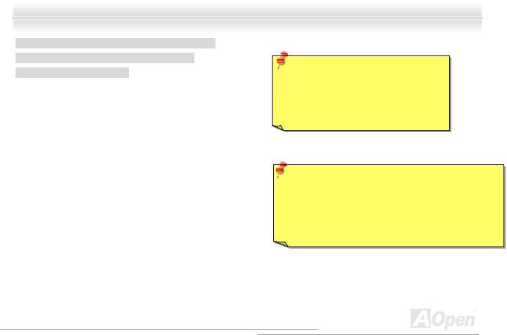
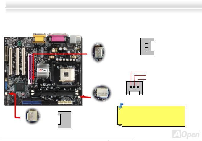
CPU and System Fan Connector (with H/W Monitoringg))
Plug in the CPU fan cable to the 3-pin CPUFAN1 connector. If you have chassis fan, you can also plug it on SYSFAN2 or
SYSFAN3 connector.
SYSFAN2 Connector
CPUFAN1 Connector


 GND
GND


 +12V
+12V


 SENSOR
SYSFAN3 Connector
GND 

 +12V
+12V 

 SENSOR


GND +12V SENSOR
Note: Some CPU fans do not have sensor pin, so that they cannot support hardware monitoring function.
28
Online Manual
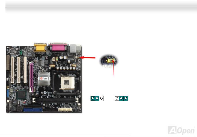
JP28 Keyboard/Mouse Wake-up Enable/Disable Jumpeerr
This motherboard provides keyboard / mouse wake-up function. You can use JP28 to enable or disable this function, which could resume your system from suspend mode with keyboard or mouse. The factory default setting is set to “Enable”(1-2), and you may disable this function by setting the jumper to 2-3.
|
Pin1 |
1 |
1 |
Disable |
Enable |
|
(Default) |
29
Online Manual
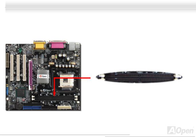
DIMM Sockets support PC100/133
This motherboard has two 168-pin SDRAM DIMM sockets that allow you to install PC100 and PC133 memory up to 2GB.
DIMM1
DIMM2
30
Loading...