


MODELS |
EQ 280 G |
|
EQ 380 G |
INSTALLATIONAND USER
INSTRUCTION
UNITED KINGDOM / IRELAND
WATERSTORAGEHEATERS
Read these installation instructions first before installing the appliance. Carefully read the user instructions before igniting the appliance. Failure to follow these instructions may lead to risk of explosion and/or fire and could cause material damage and/or bodily harm.
Installation and commissioning should be carried out by a qualified competent installer. The type of gas and the value at which the appliance is set standard in the factory are registered on the rating plate. The appliance may only be installed in a room if this room meets the ventilation requirements.
A.O. SMITH ACCEPTS NO RESPONSIBILITY FOR WARRANTY, SERVICE AND/OR PRODUCTLIABILITYINCASEOFUNAUTHORIZEDALTERATIONS,PRODUCT MODIFICATIONSORREPAIR.
2
CONTENTS |
PAGE |
|
1. |
General. ......................................................................................................... |
4 |
1.1 |
- Description of the appliance .......................................................................... |
4 |
1.2 |
- Technical safety equipment ........................................................................... |
6 |
1.3 |
- Technical description ..................................................................................... |
8 |
1.3.1 |
- Dimensions .................................................................................................... |
8 |
1.3.2 |
- Technical data ............................................................................................. |
10 |
2. |
For the installer. ......................................................................................... |
12 |
2.1 |
- Installation instructions ................................................................................ |
12 |
2.1.1 |
- Installation .................................................................................................... |
12 |
2.1.2 |
- Water connection ........................................................................................ |
12 |
2.1.3 |
- Gas connection ........................................................................................... |
13 |
2.1.4 |
- Flue system ................................................................................................. |
14 |
2.1.5 |
- Flue down draught safety device ................................................................ |
14 |
2.2 |
- Commissioning ............................................................................................. |
15 |
2.3 |
- Pilot adjustment ............................................................................................ |
16 |
2.4 |
- Putting out of operation ................................................................................ |
16 |
2.5 |
- Temperature regulation ................................................................................ |
16 |
2.6 |
- Setting the nominal heat input ...................................................................... |
17 |
2.7 |
- Conversion procedure ................................................................................. |
17 |
2.8 |
- Maintenance ................................................................................................ |
19 |
2.8.1 |
- Sacrificial anode .......................................................................................... |
19 |
2.8.2 |
- Cleaning ....................................................................................................... |
19 |
2.8.3 |
- Decalcification ............................................................................................. |
20 |
2.8.4 |
- Spare parts .................................................................................................. |
20 |
2.9 |
- Inlet combination .......................................................................................... |
20 |
2.10 |
- Fault finding ................................................................................................. |
20 |
2.11 |
- Gas smell ..................................................................................................... |
21 |
2.12 |
- Condensation ............................................................................................... |
21 |
2.13 |
- Important warning ........................................................................................ |
21 |
3. |
For the user. ............................................................................................... |
22 |
3.1 |
- Commissioning ............................................................................................. |
22 |
3.2 |
- Use .............................................................................................................. |
22 |
3.3 |
- Putting out of operation ................................................................................ |
22 |
3.4 |
- Fault finding ................................................................................................. |
23 |
4. |
Guarantee. .................................................................................................. |
24 |
3
1.GENERAL
1.1Description of the appliance
Construction of the water heater is in accordance with the European standard for gas heated water storage heaters for sanitary application (EN 89). The appliance thus meets the European Directory for Gas Appliances and is therefore entitled to carry the CEmarking. It is an open flued appliance without ventilator and with a flue gas down draught safeguard (category B11BS). The water heater is suitable for a maximum working pressure of 8 bar. The water-heater tank is manufactured from low carbon sheet steel and is glass-lined on the inside. In addition the tank is fitted with a sacrificial anode as an extra protection against corrosion. A thick PU-insulation layer covered in a steel jacket reduces unnecessary heat loss. When the appliance is filled with water it continuously is under water pressure. As hot water is drained from the tank, cold water is added immediately. Four flue baffles has been placed in the flue tube to improve heat transfer. The flue gasses pass their heat on to the water by means of radiation and convection. The flue gasses are guided to the chimney via the draught diverter. The exhaust of the flue gasses is realized by natural thermal draught (see drawing 1).
Dead legs on a hot water installation are undesireable. Where possible they should be avoided. Where the inclusion on the system of a dead leg is unavoidable the following restrictions should be applied:
-for pipes not exceeding 19 mm. inside diameter; maximum lengh of dead leg permitted 12.0 metres;
-for pipes exceeding 19 mm. but not exceeding 25 mm. inside diameter; maximum length of dead leg 7.5 metres;
-for pipes with an inside diameter
exceeding 25 mm. maximum dead leg 3.0 metres.
4

|
|
Drawing 1 - Cross-section of the |
|
|
|
appliance |
|
1) |
Draught diverter |
8) |
T&P safety connection |
2) |
Hot water outlet |
9) |
Steel jacket |
3) |
Insulation material |
10) |
Flue baffle |
4) |
Flue tube |
11) |
Sacrificial anode |
5) |
Glass lined tank |
12) |
Drain tap |
6) |
Gas control valve |
13) |
Atmospheric burner |
7) |
Cold water inlet pipe |
14) |
Pilot light burner with |
|
|
|
thermocouple |
5
1.2 Technical safety equipment
Gas control block
The water heater has been fitted with a gas control block consisting of a thermo-electrical pilot flame safeguard, pilot flame pressure regulator, burner pressure regulator, a control thermostat (adjustable between 30°C and 71°C) and a safety thermostat (82°C). This gas control block with its simple and secure control respectively switches the gas supply to the main burner on or off.
This gas control block is suitable for gasses from the first, second and third gas family. The maximum inlet pressure is 50 mbar.
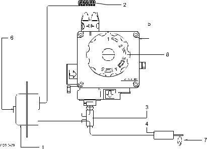
Drawing 2 - Gas control block with T.R.S.
Thermal Reflux Safeguard
The heater is fitted with a flue gas blowback safety device. The functioning of the safety device is based upon the principle of the Thermal Reflux Safeguard – TRS for short – shown in Fig.2.
This TRS can be recognized by the copper coloured spiral that is fitted to the lower edge of the draught diverter. The spiral is connected to a thermostat by means of a capillary tube. The wiring of the thermostat must be connected to the thermocouple circuit.
1)T.R.S. thermostat
2)Sensor T.R.S. thermostat
3)Thermocouple with built-in interrupter
4)Thermocouple
5)Gas control block
6)Reset button
7)Pilot burner
8)Temperature regulator knob
6
It is the aim of the T.R.S. to prevent flue gasses from the water heater entering the room where the water heater has been placed, instead of passing through the flue to outside atmosphere. The thermo-couple circuit is interrupted and the gas supply is disconnected as soon as the T.R.S. is activated by heating of the sensor by the hot gasses.
After the cause of the reentry of flue gasses has been traced the device can be put back into operation again. In case of T.R.S. the RESET button has to be pressed first.
If this failure occurs frequently, this indicates that the flue suffers from down draught conditions. We advice that necessary remedial actions be carried out by a competent person.
Important
If the water heater is put out of operation by a failure, this may be caused by the T.R.S.. If there is a RESET button on the thermostat this is visible because the button rose. The device can be put back into operation by pressing the RESET-button.
The T.R.S. should never be put out of operation. Reentry of flue gasses to the building could be harmful and cause poisoning or death.
Attention:
Instruction addition for installer.
Fitting the Thermal Reflux Safeguard:
1.Remove the two screws from the lid;
2.Position the support (with preassembled TRS) onto the lid;
3.Secure the support, using both screws;
4.Interconnect the male and female connectors on the lid.
7

1.3Technical description
1.3.1Dimensions
These water heaters are only suitable for a flue tube with minimal the announced diameter (dimension G).
Dim. |
EQ 280 |
EQ 380 |
(zie fig.3) |
|
|
A |
1585 |
1780 |
B |
1450 |
1640 |
D |
645 |
675 |
F |
730 |
765 |
G |
130 |
130 |
K |
390 |
390 |
L |
375 |
385 |
M |
1505 |
1685 |
N |
1505 |
1685 |
R |
285 |
275 |
S |
1280 |
1460 |
V |
410 |
410 |
1 |
Cold water inlet |
|
2 |
Warm water outlet |
|
3 |
Gas control block |
|
4 |
Drain tap |
|
5 |
T&P relief valve tapping |
|
All dimensions are given in mm. (rounded off on 5 mm).
8
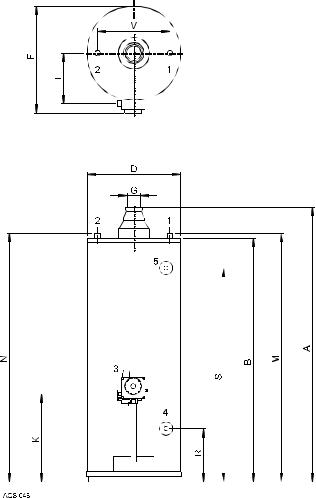
Drawing 3 - Dimensions
9
 Loading...