


28
30
50
60
Installation
User and
Service Manual
XTRA HIGH EFFICIENCY
WATER PRODUCTS
COMPANY
A DIVISION OF A. O. SMITH CORPORATION

www.aosmithinternational.com
your installer

|
|
|
gis |
|
|
Read this manual carefully |
|
|
Warning |
|
|
|
|
|
|
Read this manual carefully before starting up the water heater. Failure to |
|
|
read this manual and to follow the instructions in this manual may lead to |
|
|
accidents, personal injury, and damage to the appliance. |
|
|
|
|
|
Copyright © 2008 A.O. Smith water Products Company |
|
|
All rights reserved. |
|
|
Nothing from this publication may be copied, reproduced and/or published by |
|
|
means of printing, photocopying or by whatsoever means, without the prior |
|
|
written approval of A.O. Smith water Products Company. |
|
|
A.O. Smith water Products Company reserves the right to modify specifications |
|
|
stated in this manual. |
|
Trademarks |
Any brand names mentioned in this manual are registered trademarks of their |
|
|
respective owners. |
|
Liability |
A.O. Smith water Products Company accepts no liability for claims from third |
|
|
parties arising from improper use other than that stated in this manual and in |
|
|
accordance with the General Conditions registered at the Eindhoven Chamber |
|
|
of Commerce. |
|
|
Refer further to the General Conditions. These are available on request, free of |
|
|
charge. |
|
|
Although considerable care has been taken to ensure a correct and suitably |
|
|
comprehensive description of all relevant components, the manual may |
|
|
nonetheless contain errors and inaccuracies. |
|
|
Should you detect any errors or inaccuracies in the manual, we would be |
|
|
grateful if you would inform us. This helps us to further improve our |
|
|
documentation. |
|
More information |
If you have any comments or queries concerning any aspect related to the |
|
|
appliance, then please do not hesitate to contact: |
|
|
A.O. Smith water Products Company |
|
|
PO Box 70 |
|
|
5500 AB Veldhoven |
|
|
Netherlands |
|
|
Telephone: |
(free) 0870 - AOSMITH |
|
|
0870 - 267 64 84 |
|
General: |
+31 40 294 25 00 |
|
Fax: |
+31 40 294 25 39 |
|
E-mail : |
info@aosmith.nl |
|
Website: |
www.aosmithinternational.com |
In the event of problems with connecting to the gas, electricity or water supply, please contact your installation's supplier/installation engineer .
Instruction manual BFC |
3 |

gis
4 |
Instruction manual BFC |

gis
Table of contents
1 |
Introduction - - |
- |
- |
- |
- |
- |
- |
- |
|
- |
- |
- |
- |
- |
- |
- |
|
- |
- |
- |
- |
- |
- |
- |
- |
- |
|
- |
- 9 |
1.1 |
About the appliance |
- |
- |
- |
- |
- |
- |
- |
- |
- |
- |
- |
- |
- |
- |
- |
- |
- |
- |
- |
- |
- |
- |
- |
- |
- |
- |
- |
- 9 |
1.2 |
What to do if you smell gas- |
- |
- |
- |
- |
- |
- |
- |
- |
- |
- |
- |
- |
- |
- |
- |
- |
- |
- |
- |
- |
- |
- |
- |
- 9 |
||||
1.3 |
Regulations - - - - - - - - - - - |
- |
- |
- |
- |
- |
- |
- |
- |
- |
- |
- |
- |
- |
- |
- |
- |
- |
- |
- |
- |
- 9 |
|||||||
1.4 |
Target groups - - - - - - - - - - |
- |
- |
- |
- |
- |
- |
- |
- |
- |
- |
- |
- |
- |
- |
- |
- |
- |
- |
- |
- |
10 |
|||||||
1.5 |
Maintenance - - - - - - - - - - - |
- |
- |
- |
- |
- |
- |
- |
- |
- |
- |
- |
- |
- |
- |
- |
- |
- |
- |
- |
- |
10 |
|||||||
1.6 |
Forms of notation - |
- |
- |
- |
- |
- |
- |
- |
- |
- |
- |
- |
- |
- |
- |
- |
- |
- |
- |
- |
- |
- |
- |
- |
- |
- |
- |
- |
11 |
1.7 |
Overview of this document - |
- |
- |
- |
- |
- |
- |
- |
- |
- |
- |
- |
- |
- |
- |
- |
- |
- |
- |
- |
- |
- |
- |
- |
12 |
||||
2 |
Working principle of the appliance- - - - - - - - - - - - - - - |
|
13 |
||||||||||||||||||||||
2.1 |
Introduction - - - - - - - - - |
- - - - - - |
- |
- |
- |
- |
- |
- |
- |
- |
- |
- |
- |
- |
- |
- |
- |
- |
13 |
||||||
2.2 |
General working principle of the appliance |
- |
- |
- |
- |
- |
- |
- |
- |
- |
- |
- |
- |
- |
- |
- |
- |
13 |
|||||||
2.3 |
The appliance's heating cycle |
- |
- |
- |
- |
- |
- |
- |
- |
- |
- |
- |
- |
- |
- |
- |
- |
- |
- |
- |
- |
- |
- |
14 |
|
2.4 |
Protection for the appliance |
- |
- |
- |
- |
- |
- |
- |
- |
- |
- |
- |
- |
- |
- |
- |
- |
- |
- |
- |
- |
- |
- |
- |
14 |
2.5 |
Safety of the installation - - |
- |
- |
- |
- |
- |
- |
- |
- |
- |
- |
- |
- |
- |
- |
- |
- |
- |
- |
- |
- |
- |
- |
- |
16 |
3 |
Installation - - - - - - - - - - - - - - - - - - - - |
- |
- |
- |
- |
- |
- |
|
- |
17 |
||||||||||||||||||||
3.1 |
Introduction - - - - - - - - - - - - |
- - - - - |
- |
- |
- |
- |
- |
- |
- - - - - - |
- |
- |
17 |
||||||||||||||||||
3.2 |
Packaging - - - - - - - - - - - - - - - - - - - - - - - - - - - - - - - - |
17 |
||||||||||||||||||||||||||||
3.3 |
Environmental conditions- - - - - - - - - - - - - - - - - |
- |
- |
- |
- |
- |
- |
- |
- |
17 |
||||||||||||||||||||
3.4 |
Technical specifications |
- |
- |
- |
- |
- |
- |
- |
- |
- |
- |
- |
- |
- |
- |
- |
- |
- |
- |
- |
- |
- |
- |
- |
- |
- |
20 |
|||
3.5 |
Installation diagram |
- |
- |
- |
- |
- |
- |
- |
- |
- |
- |
- |
- |
- |
- |
- |
- |
- |
- |
- |
- |
- |
- |
- |
- |
- |
- |
- |
23 |
|
3.6 |
Water connections, Unvented |
- |
- |
- |
- |
- |
- |
- |
- |
- |
- |
- |
- |
- |
- |
- |
- |
- |
- |
- |
- |
- |
- |
24 |
||||||
3.7 |
Water connections, Vented- |
- |
- |
- |
- |
- |
- |
- |
- |
- |
- |
- |
- |
- |
- |
- |
- |
- |
- |
- |
- |
- |
- |
- |
25 |
|||||
3.8 |
Gas connection - |
- |
- |
- |
- |
- |
- |
- |
- |
- |
- - - - - |
- |
- |
- |
- |
- |
- |
- |
- |
- |
- |
- |
- |
- |
- |
26 |
||||
3.9 |
Air supply and flue - - - - - - - - - - - - - - - - - |
- |
- |
- |
- |
- |
- |
- |
- |
- |
- |
- |
26 |
|||||||||||||||||
3.10 |
Electrical connection - - - - - - - - - - - - - - - - |
- |
- |
- |
- |
- |
- |
- |
- |
- |
- |
- |
32 |
|||||||||||||||||
3.11 |
Checking the supply pressure and burner pressure - |
- |
- |
- |
- |
- |
- |
- |
- |
- |
- |
- |
36 |
|||||||||||||||||
4 |
Conversion to a different gas category |
- |
- |
- |
|
- |
- |
- |
- |
- |
- |
- |
- |
|
- |
39 |
||||||||||||||
5 |
Filling - - - - - - - - - - - - - |
- - - - - |
- |
- |
- |
|
- |
- |
- |
- |
- |
- |
- |
- |
|
- |
43 |
|||||||||||||
5.1 |
Filling the appliance - - - - - - - - - - - - - - - - |
- |
- |
- |
- |
- |
- |
- |
- |
- |
- |
- |
44 |
|||||||||||||||||
6 |
Draining - - - |
- |
- |
- |
- |
- |
- |
|
- |
- |
- - - - - |
- |
- |
- |
|
- |
- |
- |
- |
- |
- |
- |
- |
|
- |
45 |
||||
6.1 |
Draining unvented installations - - - - - - - - - - - - - - |
- |
- |
- |
- |
- |
- |
- |
- |
46 |
||||||||||||||||||||
6.2 |
Draining vented installations |
- |
- |
- |
- |
- - - - - |
- |
- |
- |
- |
- |
- |
- |
- |
- |
- |
- |
- |
- |
- |
46 |
|||||||||
7 |
The control panel- - - - - - - - - - - - - - - - - |
- |
- |
- |
- |
- |
- |
|
- |
49 |
||||||||||||||||||||
7.1 |
Introduction - - - - - - - - - - - - |
- - - - - |
- |
- |
- |
- |
- |
- |
- |
- |
- |
- |
- |
- |
- |
- |
49 |
|||||||||||||
7.2 |
Controls - - - - - - - - - - - - - - - - - - - |
- |
- |
- |
- |
- |
- |
- |
- |
- |
- |
- |
- |
- |
- |
49 |
||||||||||||||
7.3 |
Meaning of icons- - - - - - - - - - - - - - - - - - |
- |
- |
- |
- |
- |
- |
- |
- |
- |
- |
- |
49 |
|||||||||||||||||
7.4 |
Electronic controller ON/OFF switch |
- |
- |
- |
- |
- |
- |
- |
- |
- |
- |
- |
- |
- |
- |
- |
- |
- |
- |
- |
49 |
|||||||||
7.5 |
Navigation buttons - - - - - - |
- |
- |
- |
- |
- |
- |
- |
- |
- |
- |
- |
- |
- |
- |
- |
- |
- |
- |
- |
- |
- |
- |
49 |
||||||
7.6 |
PC connection - - - - - - - - - - - |
- - - - - |
- |
- |
- |
- |
- |
- |
- - - - - - |
- |
- |
50 |
||||||||||||||||||
8 |
Status of the appliance - - - - - - - - - - - - - - - - - - - - |
|
- |
51 |
||||||||||||||||||||||||||
8.1 |
Introduction - - - - - - - - - - - - |
- |
- |
- |
- |
- |
- |
- |
- |
- |
- |
- |
- |
- |
- |
- |
- |
- |
- |
- |
51 |
|||||||||
8.2 |
Operating modes |
- |
- |
- |
- |
- |
- |
- |
- |
- |
- |
- |
- |
- |
- |
- |
- |
- |
- |
- |
- |
- |
- |
- |
- |
- |
- |
- |
- |
51 |
8.3 |
Error conditions - |
- |
- |
- |
- |
- |
- |
- |
- |
- |
- |
- |
- |
- |
- |
- |
- |
- |
- |
- |
- |
- |
- |
- |
- |
- |
- |
- |
- |
52 |
8.4 |
Service condition- |
- |
- |
- |
- |
- |
- |
- |
- |
- |
- |
- |
- |
- |
- |
- |
- |
- |
- |
- |
- |
- |
- |
- |
- |
- |
- |
- |
- |
53 |
Instruction manual BFC |
5 |

Table of contents
9 |
Starting and running - - |
- |
- |
- |
- |
|
- |
- |
|
- |
- |
- |
- |
- |
- |
- |
|
- |
- |
- |
- |
- |
- |
- |
55 |
||
9.1 |
Introduction - - - - - |
- |
- - - |
- |
- |
- |
- |
- |
|
- |
- |
- |
- |
- |
- |
- |
- |
- |
- |
- |
- |
- |
- |
- |
- |
- |
- 55 |
9.2 |
Starting and running- |
- |
- - - |
- - - |
- |
- |
- |
- |
- |
- |
- |
- |
- |
- |
- |
- |
- |
- |
- |
- |
- |
- |
- |
- 55 |
|||
9.3 |
The appliance's heating cycle - |
- |
- |
- |
- |
- |
- |
- |
- |
- |
- |
- |
- |
- |
- |
- |
- |
- |
- |
- |
- |
- |
- 55 |
||||
10 |
Shutting down - - - - - - - - |
- |
- |
- |
|
- |
- |
- |
- |
- |
- |
|
- |
- |
- |
- |
- |
- |
- |
- |
57 |
10.1 |
Introduction - - - - - - - - - - - - |
- |
- |
- |
- |
- |
- |
- |
- |
- |
- |
- |
- |
- |
- |
- |
- |
- |
- |
- |
- 57 |
10.2 |
Shut the appliance down for a brief period ("OFF mode")- |
- |
- |
- |
- |
- |
- |
- |
- |
- 57 |
|||||||||||
10.3 |
Electrically isolating the appliance - |
- |
- |
- |
- |
- |
- |
- |
- - |
- |
- - - |
- |
- |
- |
- |
- |
- |
- 57 |
|||
10.4 |
Shutting the appliance down for a long period |
- |
- |
- |
- |
- |
- |
- |
- |
- |
- |
- |
- |
- |
- |
- 57 |
|||||
11 |
Main menu - - - - - - - |
- - |
- |
- |
- |
- |
- - - - |
- |
- |
- |
|
- |
- |
- |
- |
- |
- |
- |
59 |
|
11.1 |
Introduction - - - - - - - - - - |
- |
- |
- - - - - - - - |
- |
- |
- |
- |
- |
- |
- |
- |
- |
- |
- |
- 59 |
||||
11.2 |
Notational convention for menu-related instructions |
- |
- |
- |
- |
- |
- |
- |
- |
- |
- |
- |
- 59 |
|||||||
11.3 |
Switching on the "ON mode" |
- |
- |
- |
- |
- |
- |
- - - - - |
- |
- |
- |
- |
- |
- |
- |
- |
- |
- |
- |
- 59 |
11.4 |
Setting the water temperature - |
- |
- |
- |
- - - - - - - |
- |
- |
- |
- |
- |
- |
- |
- |
- |
- |
- |
- 59 |
|||
11.5 |
Week program - - - - - - - |
- |
- |
- |
- |
- |
- |
- - - - - |
- |
- |
- |
- |
- |
- |
- |
- |
- |
- |
- |
- 60 |
11.6 |
Starting and stopping the week program - |
- - - - - |
- |
- |
- |
- |
- |
- |
- |
- |
- |
- |
- |
- 60 |
||||||
11.7 |
Changing the appliance's standard week program - |
- |
- |
- |
- |
- |
- |
- |
- |
- |
- |
- |
- 60 |
|||||||
11.8 |
Adding times to a week program- |
- |
- |
- |
- |
- - - - - |
- |
- |
- |
- |
- |
- |
- |
- |
- |
- |
- |
- 62 |
||
11.9 |
Deleting times from a week program- |
- |
- |
- - - - - |
- |
- |
- |
- |
- |
- |
- |
- |
- |
- |
- |
- 63 |
||||
11.10 |
Extra period- - - - - - - - - - |
- |
- |
- |
- - - - - - - |
- |
- |
- |
- |
- |
- |
- |
- |
- |
- |
- |
- 63 |
|||
11.11 |
Programming an extra period |
- |
- |
- |
- |
- - - - - - - |
- |
- |
- |
- |
- |
- |
- |
- |
- |
- |
- |
- 64 |
||
11.12 |
Settings- - - - - - - - - - - |
- |
- |
- |
- |
- |
- |
- - - - - |
- |
- |
- |
- |
- |
- |
- |
- |
- |
- |
- |
- 65 |
12 |
Service program - - - |
- |
- |
- |
- |
- |
|
- - |
|
- |
- |
- |
- |
- |
- |
- |
|
- - |
|
- |
- |
- |
- |
- |
67 |
12.1 |
Introduction - - - - - - - - - - - |
- |
- |
- |
- |
- |
- |
- |
- |
- |
- |
- |
- |
- |
- |
- |
- |
- |
- |
- |
- |
- 67 |
|||
12.2 |
Setting the hysteresis - - - |
- |
- |
- |
- |
- |
- |
- |
- |
- |
- |
- |
- |
- |
- |
- |
- |
- |
- |
- |
- |
- |
- |
- |
- 67 |
12.3 |
Displaying the error history |
- |
- |
- |
- |
- |
- |
- |
- |
- |
- |
- |
- |
- |
- |
- |
- |
- |
- |
- |
- |
- |
- |
- |
- 67 |
12.4 |
Displaying the appliance history - |
- |
- |
- |
- |
- |
- |
- |
- |
- |
- |
- |
- |
- |
- |
- |
- |
- |
- |
- |
- |
- 68 |
|||
12.5 |
Display the selected appliance |
- |
- |
- |
- |
- |
- |
- |
- |
- |
- |
- |
- |
- |
- |
- |
- |
- |
- |
- |
- |
- |
- 68 |
||
12.6 |
Switching the pump on or off |
- |
- |
- |
- |
- |
- |
- |
- |
- |
- |
- |
- |
- |
- |
- |
- |
- |
- |
- |
- |
- |
- |
- 68 |
|
12.7 |
Setting the service interval |
- |
- |
- |
- |
- |
- |
- |
- |
- |
- |
- |
- |
- |
- |
- |
- |
- |
- |
- |
- |
- |
- |
- |
- 68 |
12.8 |
Setting the display contrast |
- |
- |
- |
- |
- |
- |
- |
- |
- |
- |
- |
- |
- |
- |
- |
- |
- |
- |
- |
- |
- |
- |
- |
- 68 |
12.9 |
Setting the display backlight time |
- |
- |
- |
- |
- |
- |
- |
- |
- |
- |
- |
- |
- |
- |
- |
- |
- |
- |
- |
- |
- 68 |
|||
12.10 |
Setting the display scroll speed |
- |
- |
- |
- |
- |
- |
- |
- |
- |
- |
- |
- |
- |
- |
- |
- |
- |
- |
- |
- |
- |
- 68 |
||
13 |
Troubleshooting - - - - - - - - - - - - - - - - - - - - - - - - 69 |
||||||
13.1 |
Introduction - - - - - - - - - - - - - - - - - - - - |
- |
- |
- |
- - - - - - - |
- |
- 69 |
13.2 |
Troubleshooting table for general errors - - - - - - - - - - - - - - - - - - 70 |
||||||
13.3 |
Troubleshooting table for displayed errors - - - - - |
- |
- |
- |
- - - - - - - |
- |
- 72 |
14 |
Maintenance frequency - |
- |
- |
- |
- |
- |
- |
|
- |
- |
- |
- |
- |
- |
- |
|
- |
- |
- |
- |
- |
- |
- |
83 |
|||
14.1 |
Introduction - - - - - - - |
- - |
- |
- |
- |
- |
- |
- |
- |
- |
- |
- |
- |
- |
- |
- |
- |
- |
- |
- |
- |
- |
- |
- |
- 83 |
||
14.2 |
Determining service interval - |
- - |
- |
- |
- |
- - |
- - - |
- - |
- - |
- |
- - |
- - |
- - - - 83 |
||||||||||||||
15 |
Performing maintenance - - - - - - - - - - - - - - - - - - - - |
85 |
|||||||||||||||||||||||||
15.1 |
Introduction - - - - - - - |
- - |
- |
- |
- |
- |
- |
- |
- |
- |
- |
- |
- |
- |
- |
- |
- |
- |
- |
- |
- |
- |
- |
- |
- 85 |
||
15.2 |
Preparation for maintenance |
- |
- |
- |
- |
- |
- |
- |
- |
- |
- |
- |
- |
- |
- |
- |
- |
- |
- |
- |
- |
- |
- |
- 85 |
|||
15.3 |
Water-side maintenance |
- |
- |
- |
- |
- |
- |
- |
- |
- |
- |
- |
- |
- |
- |
- |
- |
- |
- |
- |
- |
- |
- |
- |
- |
- 87 |
|
15.4 |
Gas-side maintenance |
- |
- |
- |
- |
- |
- |
- |
- |
- |
- |
- |
- |
- |
- |
- |
- |
- |
- |
- |
- |
- |
- |
- |
- |
- |
- 88 |
15.5 |
Finalizing maintenance |
- |
- |
- |
- |
- |
- |
- |
- |
- |
- |
- |
- |
- |
- |
- |
- |
- |
- |
- |
- |
- |
- |
- |
- |
- |
- 88 |
16 |
Warranty (certificate) - |
- |
- |
- |
- |
- |
- |
- |
|
- |
- |
- |
- |
- |
- |
- |
|
- |
- |
- |
- |
- |
- |
- |
89 |
||
16.1 |
General warranty - - - |
- |
- |
- |
- |
- |
- |
- |
- |
- |
- |
- |
- |
- |
- |
- |
- |
- |
- |
- |
- |
- |
- |
- |
- |
- |
- 89 |
6 |
Instruction manual BFC |

|
|
|
|
|
|
|
|
|
|
|
|
|
|
|
|
|
|
|
|
|
|
|
|
16.2 |
Tank warranty - - - - - - - - - - |
- |
- |
- |
- |
- |
- |
- |
- |
- |
- |
- |
- |
- |
- |
- |
- |
- |
- |
- |
- |
89 |
|
16.3 |
Conditions for Installation and use |
- |
- |
- |
- |
- |
- |
- |
- |
- |
- |
- |
- |
- |
- |
- |
- |
- |
- |
- |
- |
89 |
|
16.4 |
Exclusions - - - - - - - - - - - - |
- |
- |
- |
- |
- |
- |
- |
- |
- |
- |
- |
- |
- |
- |
- |
- |
- |
- |
- |
- |
90 |
|
16.5 |
Scope of the warranty - - |
- - - - |
- |
- |
- |
- |
- |
- |
- |
- |
- |
- |
- |
- |
- |
- |
- |
- |
- |
- |
- |
- |
90 |
16.6 |
Claims - - - - - - - - - - - - - - |
- |
- |
- |
- |
- |
- |
- |
- |
- |
- |
- |
- |
- |
- |
- |
- |
- |
- |
- |
- |
90 |
|
16.7 |
Obligations of A.O. Smith |
- - - - |
- - - - - - - - - - - - - - - - - - - |
- |
90 |
||||||||||||||||||
17 |
Appendices- - - - - - - - - - - - - - - - - - - - - - - - - - - |
|
91 |
||||||||||||||||||||
17.1 |
Introduction - - - - - - - - - - - |
- |
- |
- |
- |
- |
- |
- |
- |
- |
- |
- |
- |
- |
- |
- |
- |
- |
- |
- |
- |
91 |
|
17.2 |
Electrical diagram - - - - - - - - |
- |
- |
- |
- |
- |
- |
- |
- |
- |
- |
- |
- |
- |
- |
- |
- |
- |
- |
- |
- |
92 |
|
17.3 |
Week program card - - - |
- - - - |
- |
- |
- |
- |
- |
- |
- |
- |
- |
- |
- |
- |
- |
- |
- |
- |
- |
- |
- |
- |
95 |
Instruction manual BFC |
7 |

Table of contents
8 |
Instruction manual BFC |

gis
1Introduction
1.1About the appliance This manual describes how to install, service and use the BFC appliance. The
0063
1.2What to do if you smell gas
1.3Regulations
BFC appliance is a condensing water heater with a fan in the air intake. The BFC can be installed as either an open or room-sealed appliance. A concentric chimney connector is fitted standard to the appliance. Alternatively, the appliance can be connected using a parallel system.
The alternative installation types are B23, C13, C33, C43, C53 and C63.
The information in this manual applies to the: BFC 28, BFC 30, BFC 50 and BFC 60.
The appliance has been manufactured and equipped in accordance with the European standard for gas-fired storage water heaters for the production of domestic hot water (EN 89). The appliances are therefore compliant with the European Directive for Gas Appliances, and and are entitled to bear the CE mark.
Warning
Read this manual carefully before starting up the water heater. Failure to read the manual and to follow the printed instructions may lead to personal injury and damage to the appliance.
Warning
If there is a gas smell:
No naked flames! No smoking!
Avoid causing sparks! Do not use any electrical equipment or switch, i.e. no telephones, plugs or bells!
Open windows and doors!
Shut off the mains gas supply valve!
Warn occupants and leave the building!
After leaving the building, alert the gas distribution company or your installation engineer.
As the (end) user, installation engineer or service and maintenance engineer, you must ensure that the entire installation complies, as a minimum, with the official local:
•building regulations;
•energy supplier's directives for existing gas installations;
•directives and technical guidelines for natural gas installations;
•safety requirements for low-voltage installations;
•regulations governing the supply of drinking water;
•regulations governing ventilation in buildings;
•regulations governing the supply of air for combustion;
•regulations governing the discharge of products of combustion;
•requirements for installations that consume gas;
•regulations governing indoor waste water disposal;
Instruction manual BFC |
9 |
1
1.4Target groups
1.5Maintenance
Introduction |
gis |
|
• regulations imposed by fire brigade, power companies and municipality. Furthermore, the installation must comply with the manufacturer's instructions.
Note
Later amendments and/or additions to all regulations, requirements and guidelines published on or prior to the moment of installing, will apply to the installation.
The three target groups for this manual are:
•(end) users;
•installation engineers;
•service and maintenance engineers.
Symbols on each page indicate the target groups for whom the information is intended. See the table.
Target group symbols
Symbol |
Target group |
|
|
|
(End) user |
|
|
|
Installation engineer |
|
|
|
Service and maintenance engineer |
|
|
A service should be carried out at least once a year, both on the water side and on the gas side. Maintenance frequency depends, among other things, on the water quality, the average burning time per day and the set water temperature.
Note
To determine the correct maintenance frequency, it is recommended to arrange for the service and maintenance engineer to check the appliance on both the water and gas side within three months following installation. Based on this check, the best maintenance frequency can be determined.
Note
Regular maintenance extends the service life of the appliance.
Note
Both the end user and the service and maintenance engineer are responsible for regular maintenance. They will need to establish clear agreements on this.
Note
If the appliance is not regularly maintained, the warranty will become void.
10 |
Instruction manual BFC |
gis
1.6Forms of notation The following notation is used in this manual:
Note
Important information.
Attention
Ignoring this information can lead to the appliance being damaged.
Warning
Failure to carefully read this information may lead to personal injury and serious damage to the appliance.
Instruction manual BFC |
11 |
|
1 |
|
Introduction |
gis |
||
|
|
|||||
1.7 Overview of this |
|
|
|
|||
|
The table provides an overview of the contents of this document. |
|||||
|
document |
|
Contents of this document |
|||
|
|
|
||||
|
|
|
|
|
|
|
|
Chapter |
|
Target groups |
|
Description |
|
|
Working principle of the |
|
|
|
This chapter describes how the appliance functions. |
|
|
appliance |
|
|
|
|
|
|
|
|
|
|
|
|
|
Installation |
|
|
|
This chapter describes the installation activity to be |
|
|
|
|
|
|
completed before you actually start up the appliance. |
|
|
|
|
|
|
|
|
|
Filling |
|
|
|
This chapter describes how to fill the appliance. |
|
|
|
|
|
|
|
|
|
Draining |
|
|
|
This chapter describes how to drain the appliance. |
|
|
|
|
|
|
|
|
|
The control panel |
|
|
|
This chapter describes the general control of the |
|
|
|
|
|
|
appliance using the display. |
|
|
|
|
|
|
|
|
|
Status of the appliance |
|
|
|
This chapter describes the status (mode or condition) that |
|
|
|
|
|
|
the appliance may have, and possible actions to take. |
|
|
|
|
|
|
|
|
|
Starting and running |
|
|
|
This chapter describes how to start the appliance running. |
|
|
|
|
|
|
The general heating cycle of the appliance is also |
|
|
|
|
|
|
described. |
|
|
Shutting down |
|
|
|
This chapter describes how to shut the appliance down for |
|
|
|
|
|
|
a brief or long period of time. |
|
|
|
|
|
|
|
|
|
Main menu |
|
|
|
This chapter describes the main menu of the display. This |
|
|
|
|
|
|
is the actual menu for the user, however the installation |
|
|
|
|
|
|
engineer and service and maintenance engineers will also |
|
|
|
|
|
|
need to use this menu. |
|
|
Service program |
|
|
|
This chapter describes the service menu. It is mainly |
|
|
|
|
|
|
intended for the installation engineer and service and |
|
|
|
|
|
|
maintenance engineers. End users may also refer to this |
|
|
|
|
|
|
chapter for additional information about the appliance. |
|
|
Troubleshooting |
|
|
|
This chapter is mainly intended for the installation |
|
|
|
|
|
|
engineer and the service and maintenance engineer. It |
|
|
|
|
|
|
describes appliance errors. These errors are indicated on |
|
|
|
|
|
|
the display. A troubleshooting table of possible causes |
|
|
|
|
|
|
and solutions is provided. End users may also refer to this |
|
|
|
|
|
|
chapter for additional information about the appliance. |
|
|
Maintenance frequency |
|
|
|
This chapter describes how to determine the optimum |
|
|
|
|
|
|
frequency at which to carry out maintenance. Both the |
|
|
|
|
|
|
end user and the service and maintenance engineer are |
|
|
|
|
|
|
responsible for regular maintenance. They need to reach |
|
|
|
|
|
|
clear agreement on this. |
|
|
|
|
|
|
|
|
|
|
|
|
|
Note |
|
|
|
|
|
|
If the appliance is not regularly maintained, the |
|
|
|
|
|
|
warranty will become void. |
|
|
|
|
|
|
|
|
|
Performing maintenance |
|
|
|
This chapter sets out the maintenance tasks to be carried |
|
|
|
|
|
|
out during a service. |
|
|
|
|
|
|
|
|
|
Warranty (certificate) |
|
|
|
This chapter states the warranty terms and conditions. |
|
|
|
|
|
|
|
|
12 |
Instruction manual BFC |
gis
2Working principle of the appliance
2.1 |
Introduction |
Topics covered in this chapter: |
|
|
|
• General working principle of the appliance; |
|
|
|
• The appliance's heating cycle; |
|
|
|
• Protection for the appliance; |
|
|
|
• Safety of the installation. |
|
2.2 |
General working |
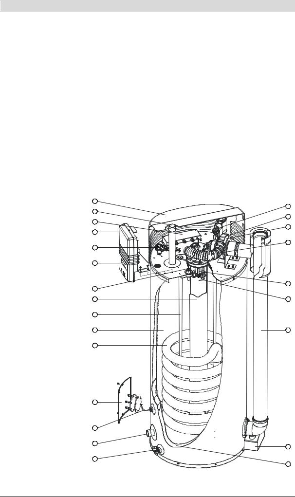
The figure shows a cut-away view of the appliance. |
|
|
principle of the |
Cut-away view of the appliance |
|
|
appliance |
||
Legend |
1 |
||
Only applicable numbers are |
2 |
||
mentioned. |
|
||
1. |
cover |
3 |
|
|
|||
2. |
hot water outlet |
4 |
|
3. |
electrical connector block |
|
|
4. |
electronic controller |
5 |
|
|
|
||
5. |
pressure switch |
6 |
|
6. |
control panel |
||
|
|||
7. |
temperature sensor T1 |
|
|
8. |
combustion chamber |
|
|
9. |
anode |
7 |
|
|
|||
10. tank |
8 |
||
11.heat exchanger
12.inspection and cleaning opening 9
13.temperature sensor T2
14. cold water inlet |
10 |
|
|
||
15. drain valve |
11 |
|
16. gas control |
||
|
||
17. burner |
|
|
18. fan |
|
|
19. air supply hose |
|
|
20. hot surface igniter |
|
|
21. flame probe |
|
|
22. chimney pipe |
12 |
|
23. siphon |
|
|
24. insulation layer |
|
|
|
13 |
14
15
16
17
18
19
20
21
22
23
24
IMD-0070 R1
Instruction manual BFC |
13 |

|
2 |
|
Working principle of the appliance |
|
|
gis
2.3The appliance's heating cycle
In this appliance the cold water enters the bottom of the tank via the cold water inlet (14). Once heated by the combustion chamber (8) and heat exchanger (11), the hot tapwater leaves the tank through the hot water outlet (2). Once the appliance is completely filled with water, it remains constantly under water supply pressure. As hot water is drawn from the appliance, it is immediately replenished with cold water.
The air required for combustion is forced into the burner (17) by the fan (18).
The gas is fed to the burner via the gas valve (16). Thanks to the modulated supply of gas and air, the optimum gas/air mixture is always achieved. The special construction of the burner causes the mixture to form a vortex (the cyclone effect), before it becomes ignited. This vorticity improves the ignition on the hot surface igniter (20), as well as ensuring optimum combustion efficiency. Through the special design of the heat exchanger (11), the flue gases are first led downwards via the combustion chamber, then upwards again via the heat exchanger, then once more downwards beside the water in the tank. In this process, the flue gases gradually become cooler. Because the cooled flue gases flow alongside the cold water lower down in the tank, they start to condense. This condensation causes latent heat energy to be released, which is transferred to the cooler water, thereby increasing the energy performance of the unit. The condensate yielded by this process is discharged via the siphon (23).
The insulation layer (24) prevents heat from escaping. The inside of the tank is enamelled to protect against corrosion. The anodes (9) provide extra protection against corrosion.
For use during maintenance, the appliance has an inspection and cleaning opening (12).
The water temperature is measured by temperature sensors T1 (7) in the top of the tank (10) and T2 (13) at the bottom of the tank. These temperatures are sent to the electronic controller. Based on these two observations, the electronic controller calculates a net water temperature: Tnet. The value of Tnet lies
between the temperatures at the top and bottom of the tank. As soon as Tnet falls below the set water temperature (Tset), the electronic controller registers a
"heat demand". The gas control (16) is opened, and the gas is mixed with air. This mixture is ignited by the hot surface igniter (20) and the water becomes
heated. As soon as Tnet rises above Tset the heat demand ends, and the electronic controller stops the heating cycle.
The electronic controller assumes a certain margin both when registering and ending heat demand. We refer to this margin as the hysteresis (12.2 "Setting the hysteresis").
2.4Protection for the appliance
2.4.1Introduction
The electronic controller monitors the water temperature and ensures safe combustion. This is achieved by:
•the Water temperature protection;
•theGas valve;
•the Fan;
•the Pressure switch;
•the Flame probe.
14 |
Instruction manual BFC |

gis
2.4.2Water temperature protection
The electronic controller uses temperatures sensors T1 (7) and T2 (13) to monitor three temperatures that are important for safety. The table explains the functioning of the temperature sensors.
Temperature protection
Protection |
Description |
|
|
Against frost |
The frost protection cuts in. The water is heated to 20°C. |
(T1 < 5°C or T2 < 5°C) |
|
|
|
For maximum water temperature |
The high-limit safeguard serves to prevent overheating and/or excessive |
(T1 > 85°C or T2 > 85°C) |
formation of scale in the appliance. If the high-limit safeguard is activated, the |
|
heating is stopped. This causes the water in the tank to cool down. Once the |
|
water has cooled sufficiently (T1 < 78°C), the electronic controller resets the |
|
appliance. |
|
|
For extra safety |
A lockout error of the water heater controller takes place. The controller must |
(T1 > 93°C or T2 > 93°C) |
be manually reset before the appliance can resume operation (8.3 "Error |
|
conditions"). The reset may only be performed if T1 <78°C. |
2.4.3Gas valve
The electronic controller opens the gas valve so that gas can be supplied to the burner. As a safety measure, the gas valve has a double shut-off. The double shut-off guarantees complete isolation of the appliance from the gas supply.
To help ensure smooth ignition, the gas valve opens gradually ('softlite").
2.4.4Fan
The fan (18) provides an optimum air supply when there is a heat demand. As a safety feature, the fan ensures that any gases present in the combustion chamber are removed, both before and after combustion. We refer to this as preand post-purge.
The fan speed is continuously monitored by the electronic controller (4). The electronic controller takes control if the speed of rotation varies too much from the set value.
2.4.5Pressure switch
The pressure switch ensures the discharge of flue gases and the supply of incoming air during the pre-purge and normal running of the appliance. The default state of the pressure switch is open. When sufficient pressure difference is reached, the pressure switch closes. However, in the event of a fault, the pressure switch is tripped open, and the heating cycle is interrupted. The table shows the trip point per appliance.
Note
The trip point of the pressure switch is not adjustable.
Pressure switch trip points
Appliance |
Closing pressure |
Opening pressure differential |
|
differential |
|
|
|
|
BFC |
> 635 Pa |
< 605 Pa |
28 |
|
|
|
|
|
BFC |
> 855 Pa |
< 825 Pa |
30 |
|
|
|
|
|
BFC |
> 885 Pa |
< 855 Pa |
50 |
|
|
|
|
|
BFC |
> 1085 Pa |
< 1055 Pa |
60 |
|
|
Instruction manual BFC |
15 |

|
2 |
|
Working principle of the appliance |
|
|
gis
2.4.6Flame probe
To ensure that no gas can flow when there is no combustion, the water heater is fitted with a flame probe (21). The electronic controller uses this probe to detect the presence of a flame, by means of ionisation detection. The electronic controller closes the gas control the instant it detects that there is a gas flow but no flame.
2.5Safety of the instal-
lation |
In addition to the appliance's standard built-in safety monitoring, the appliance |
|
must also be protected by an expansion vessel, expansion valve, pressure |
|
reducing valve, non-return valve and a T&P valve. |
|
The use of an expansion vessel, expansion valve and/or pressure reducing |
|
valve depends on the type of installation: unvented or vented. |
2.5.1Unvented installation
With an unvented installation, an expansion valve valve and expansion vessel prevent the buildup of excessive pressure in the tank. This prevents damage being caused to the enamelled coating (in the appliance) or to the tank. A nonreturn valve prevents excessive pressure buildup in the water supply system. This valve also prevents water from flowing backwards from the tank into the cold water supply system. The pressure reducing valve protects the installation against an excessively high water supply pressure (> 8 bar). These components are fitted to the cold water pipe (3.7 "Water connections, Vented").
2.5.2Vented installation
With a vented installation, excess pressure is taken up by the open cold water head tank. The height of the head tank determines the working pressure in the water heater, which may not exceed 8 bar. The installation must also be fitted with a vent pipe from the hot water pipe, that opens into the cold water tank.
Ideally, the vent pipe should discharge into a separate tundish/drain or otherwise to the open cold water head tank. The water heater should also be fitted on the hot water side with a stop valve (3.6.2 "Hot water side").
2.5.3T&P valve
A T&P valve is only mandatory in an unvented installation. However, A.O. Smith also recommends the use of a T&P valve in vented installations.
A T&P (Temperature and Pressure Relief) valve monitors the pressure in the tank and the water temperature at the top of the tank. If the pressure in the tank becomes excessive (> 10 bar) or the water temperature is too high (> 97°C), the valve will open. The hot water can now flow out of the tank. Because the appliance is under water supply pressure, cold water will automatically flow into the tank. The valve remains open until the unsafe situation has been rectified. The appliance is fitted standard with a connecting point for a T&P
valve (3.6.2 "Hot water side").
16 |
Instruction manual BFC |

is
3 Installation
Warning
Installation work should be carried out by an approved installation engineer in compliance with the general and local regulations imposed by the gas, water and power supply companies and the fire service.
The appliance may only be installed in a room that complies with the requirements stated in national and local ventilation
regulations (1.3 "Regulations").
3.1 |
Introduction |
This chapter describes the installation activities to be carried out before you |
|
|
|
actually start using the appliance (9 "Starting and running"), namely: |
|
|
|
• |
Packaging; |
|
|
• |
Environmental conditions; |
|
|
• |
Technical specifications; |
|
|
• Water connections, Unvented; |
|
|
|
• Water connections, Vented; |
|
|
|
• |
Gas connection; |
|
|
• Air supply and flue; |
|
|
|
• |
Electrical connection; |
|
|
• Checking the supply pressure and burner pressure; |
|
In the event of conversion to a different gas category, see conversion (4 "Conversion to a different gas category").
3.2 |
Packaging |
To avoid damaging the appliance, remove the packaging carefully. |
|
|
We recommend unpacking the appliance at or near its intended location. |
|
|
|
|
|
Attention |
|
|
The appliance may only be manoeuvred in an upright position. Take care |
|
|
that the appliance is not damaged after unpacking. |
3.3 |
Environmental |
|
The appliance is suitable for either open or room-sealed combustion. If |
||
|
conditions |
installed as a room-sealed appliance, then the availability of the necessary |
external air supply will depend on the place of installation. In this event, there are no additional ventilation requirements.
If the appliance is to be installed as an open system, then it will be subject to the guidelines and ventilation regulations that are in force locally.
The alternative installation types are B23, C13, C33, C43, C53 and C63.
Attention
The appliance may not be used in rooms where chemical substances are stored or used, due to the risk of explosion and/or corrosion of the appliance. Some propellants, bleaching agents, degreasing agents etc. disperse vapours which are explosive and/or which cause accelerated corrosion. If the appliance is used in a room in which such substances are present, the warranty will be void.
Instruction manual BFC |
17 |

|
3 |
|
Installation |
|
|
3.3.1Air humidity and ambient temperature
is
The boiler room must be frost-free, or be protected against frost. The table shows the environmental conditions that must be adhered to for correct functioning of the electronics present in the appliance to be guaranteed.
Air humidity and ambient temperature specifications
Air humidity and ambient temperature
Air humidity |
max. 93% RV at +25°C |
|
|
Ambient temperature |
Functional: 0 < T < 60°C |
|
|
3.3.2Appliance maximum floor load
In connection with the appliance's weight, take account of the maximum floor loading, refer to the table.
Weight specifications related to maximum floor load
Weight of the appliance filled with water
BFC 28 |
394 kg |
|
|
BFC 30, BFC 50, BFC 60 |
582 kg |
|
|
3.3.3Water composition
The appliance is intended for heating drinking water. The drinking water must comply with the regulations governing drinking water for human consumption. The table gives an overview of the specifications.
Water specifications
Water composition
Hardness |
> 1.00 mmol/l: |
(alkaline earth ions) |
• German hardness> 5.6° dH |
|
• French hardness > 10.0° fH |
|
• English hardness > 7.0° eH |
|
|
Conductivity |
> 125 µS/cm |
|
|
Acidity (pH value) |
7.0 < pH value < 9.5 |
|
|
|
|
Note
If the water specifications deviate from those stated in the table, then the tank protection cannot be guaranteed (16 "Warranty (certificate)").
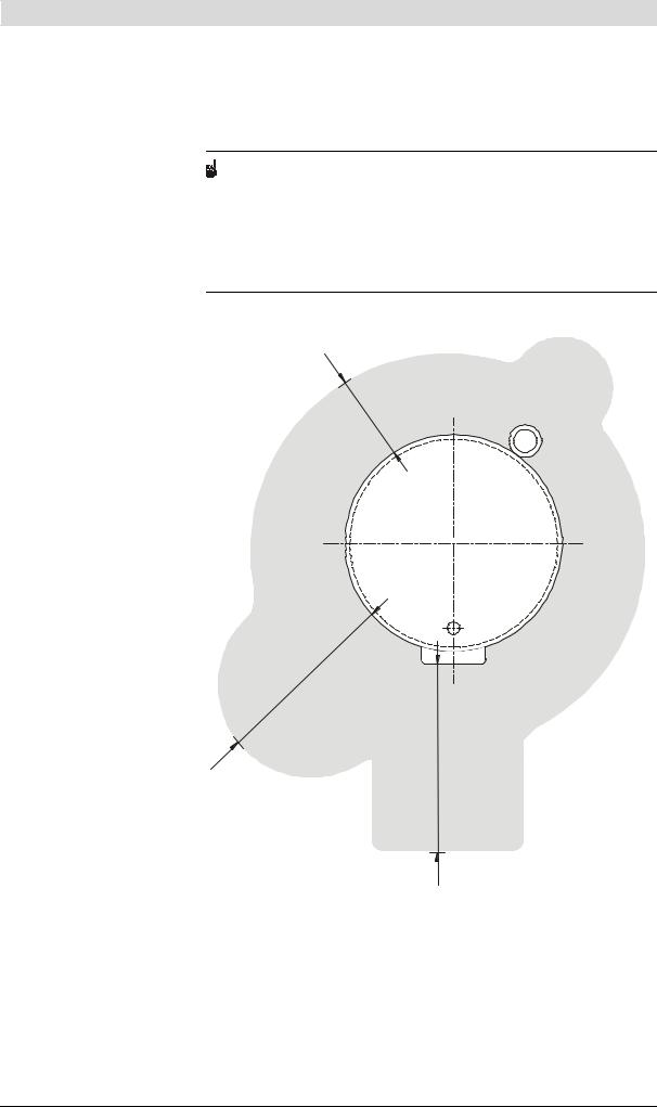
3.3.4Working clearances
For access to the appliance, it is recommended that the following clearances are observed (see figure):
•AA: around the appliance's control column and cleaning openings: 100 cm.
•BB: all sides of the appliance: 50 cm.
•Above the appliance (room to replace the anodes):
-100 cm if using fixed anodes, or
-50 cm if using flexible anodes.
18 |
Instruction manual BFC |
is
If the available clearance is less than 100 cm, flexible magnesium anodes may be ordered.
Note
When installing the appliance, be aware that any leakage from the tank and/or connections can cause damage to the immediate environment or floors below the level of the boiler room. If this is the case, the appliance should be installed above a wastewater drain or in a suitable metal leak tray.
The leak tray must have an appropriate wastewater drain and must be at least 5cm deep with a length and width at least 5cm greater than the diameter of the appliance.
Working clearances
B
B
A
A
AA
IMD-0228 R1
Instruction manual BFC |
19 |
|
3 |
|
Installation |
|
|
is
3.4Technical specifica- The appliance is supplied without accessories. Check the
tions |
dimensions (3.4.1 "Dimensions of the appliance"), gas data (3.4.3 "Gas data") |
|
and other specifications (3.4.2 "General and electrical specifications") of any |
|
accessories you plan to use. |
|
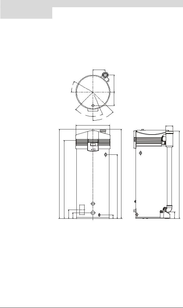
3.4.1 Dimensions of the appliance |
|
Plan and elevation of the appliance |
Legend
See the table.
Hx
3
Hy
30º
Ny
6 |
2 |
5 |
4
45º  18º
18º  45º
45º
D 2
3
5
A N
K
S
|
|
6 |
|
|
|
1 |
|
P |
M |
4 |
|
R |
|||
|
|||
|
|
G
H
7
W
IMD-0073 R5
20 |
Instruction manual BFC |
is
Dimensions (all sizes in mm, unless otherwise stated)
Dimen |
Description |
BFC |
BFC |
BFC |
BFC |
sion |
|
28 |
30 |
50 |
60 |
|
|
|
|
|
|
A |
Total height |
1390 |
1910 |
1910 |
1910 |
|
|
|
|
|
|
D |
Diameter of the appliance |
705 |
705 |
705 |
705 |
|
|
|
|
|
|
G |
Flue gas outlet diameter |
80/125 |
100/150 |
100/150 |
100/150 |
|
|
|
|
|
|
H |
Height of flue/air supply |
1365 |
1905 |
1905 |
1905 |
|
|
|
|
|
|
Hx |
x position of flue |
265 |
265 |
265 |
265 |
|
|
|
|
|
|
Hy |
y-position of flue |
375 |
375 |
375 |
375 |
|
|
|
|
|
|
K |
Height of gas connection |
1270 |
1800 |
1800 |
1800 |
|
|
|
|
|
|
M |
Height of cold water supply |
170 |
160 |
160 |
160 |
|
|
|
|
|
|
N |
Height of hot water outlet |
1405 |
1940 |
1940 |
1940 |
|
|
|
|
|
|
Ny |
y-position of hot water outlet |
205 |
205 |
205 |
205 |
|
|
|
|
|
|
P |
Height of cleaning opening |
170 |
175 |
175 |
175 |
|
|
|
|
|
|
R |
Height of drain valve connection |
85 |
75 |
75 |
75 |
|
|
|
|
|
|
S |
Height of T&P valve connection |
900 |
1410 |
1410 |
1410 |
|
|
|
|
|
|
W |
Height of condensation drain |
125 |
145 |
145 |
145 |
|
|
|
|
|
|
1 |
Cold water supply connection (ext.) |
R11/2 |
R11/2 |
R11/2 |
R11/2 |
2 |
Hot water outlet (ext.) |
R11/2 |
R11/2 |
R11/2 |
R11/2 |
3 |
Gas valve connection (int.) |
Rp3/4 |
Rp3/4 |
Rp3/4 |
Rp3/4 |
4 |
Drain valve connection (int.) |
3/4" |
3/4" |
3/4" |
3/4" |
5 |
T&P valve connection (int.) |
1-11.5 NPT |
1-11.5 NPT |
1-11.5 NPT |
1-11.5 NPT |
|
|
|
|
|
|
6 |
Inspection/cleaning opening |
95x70 |
95x70 |
95x70 |
95x70 |
|
|
|
|
|
|
7 |
Condensation drainage connection (int.) |
Ø40 |
Rp1 |
Rp1 |
Rp1 |
|
|
|
|
|
|
3.4.2General and electrical specifications
General and electrical specifications
DESCRIPTION |
Unit |
BFC 28 |
BFC 30 |
BFC 50 |
BFC 60 |
|
|
|
|
|
|
Volume |
litres |
217 |
368 |
368 |
368 |
|
|
|
|
|
|
Empty weight |
kg |
177 |
214 |
214 |
214 |
|
|
|
|
|
|
Maximum operating pressure |
bar |
8 |
8 |
8 |
8 |
|
|
|
|
|
|
Number of anodes |
- |
4 |
4 |
4 |
4 |
|
|
|
|
|
|
Fan rotation speed at ignition |
rpm |
4500 |
4500 |
4500 |
4500 |
|
|
|
|
|
|
Operational speed of fan |
rpm |
5000 |
5400 |
6000 |
6660 |
|
|
|
|
|
|
Diameter of air restrictor |
mm |
23.0 |
23.0 |
28.0 |
29.0 |
|
|
|
|
|
|
Heating time ∆T = 45°C |
minutes |
22 |
35 |
24 |
19 |
|
|
|
|
|
|
Electrical power consumption |
W |
275 |
275 |
275 |
275 |
|
|
|
|
|
|
Supply voltage |
volts |
230 |
230 |
230 |
230 |
(-15% +10% VAC) |
|
|
|
|
|
|
|
|
|
|
|
Mains frequency |
Hz (± 1Hz) |
50 |
50 |
50 |
50 |
|
|
|
|
|
|
IP class |
- |
30 |
30 |
30 |
30 |
|
|
|
|
|
|
Instruction manual BFC |
21 |

|
3 |
|
Installation |
|
|
3.4.3Gas data
Gas data
is
Description II2H3+ |
Unit |
BFC |
BFC |
BFC |
BFC |
|
|
28 |
30 |
50 |
60 |
|
|
|
|
|
|
Gas category 2H: G20 - 20 mbar |
|
|
|
|
|
Injector orifice diameter |
mm |
4.90 |
5.10 |
7.00 |
7.10 |
|
|
|
|
|
|
(1) = Blank plate |
1 or 2 |
2 |
2 |
2 |
2 |
(2) = Burner pressure regulator |
|
|
|
|
|
|
|
|
|
|
|
Nominal load (gross calorific value) |
kW |
32.1 |
34.5 |
52.6 |
63.2 |
|
|
|
|
|
|
Nominal output |
kW |
30.5 |
32.7 |
48.8 |
59.6 |
|
|
|
|
|
|
Supply pressure |
mbar |
20 |
20 |
20 |
20 |
|
|
|
|
|
|
Burner pressure |
mbar |
8.5 |
8.5 |
8.5 |
11.5 |
|
|
|
|
|
|
Gas consumption (*) |
m3/h |
3.1 |
3.3 |
5.0 |
6.0 |
General 3+ |
|
|
|
|
|
Injector orifice diameter |
mm |
2.50 |
2.60 |
3.40 |
3.80 |
|
|
|
|
|
|
(1) = Blank plate |
1 or 2 |
1 |
1 |
1 |
1 |
(2) = Burner pressure regulator |
|
|
|
|
|
|
|
|
|
|
|
Gas category: G30-30 mbar (butane) |
|
|
|
|
|
|
|
|
|
|
|
Nominal load (gross calorific value) |
kW |
30.7 |
32.8 |
50.6 |
59.4 |
|
|
|
|
|
|
Nominal output |
kW |
29.8 |
31.8 |
48.1 |
57.4 |
|
|
|
|
|
|
Supply pressure |
mbar |
30 |
30 |
30 |
30 |
|
|
|
|
|
|
Burner pressure (†) |
mbar |
- |
- |
- |
- |
Gas consumption (*) |
kg/h |
2.2 |
2.4 |
3.7 |
4.3 |
Gas category: G31-37 mbar (propane) |
|
|
|
|
|
|
|
|
|
|
|
Nominal load (gross calorific value) |
kW |
29.0 |
30.9 |
50.3 |
59.1 |
|
|
|
|
|
|
Nominal output |
kW |
28.1 |
29.8 |
47.7 |
56.9 |
|
|
|
|
|
|
Supply pressure |
mbar |
37 |
37 |
37 |
37 |
|
|
|
|
|
|
Burner pressure (†) |
mbar |
- |
- |
- |
- |
Gas consumption (*) |
kg/h |
2.1 |
2.2 |
3.6 |
4.2 |
(*) Based on 1013.25 mbar and 15 °C.
(†) If using a blank plate instead of a burner pressure regulator, it is assumed that the burner pressure is equal to the supply pressure. In practice, however, the burner pressure will be lower.
22 |
Instruction manual BFC |
is
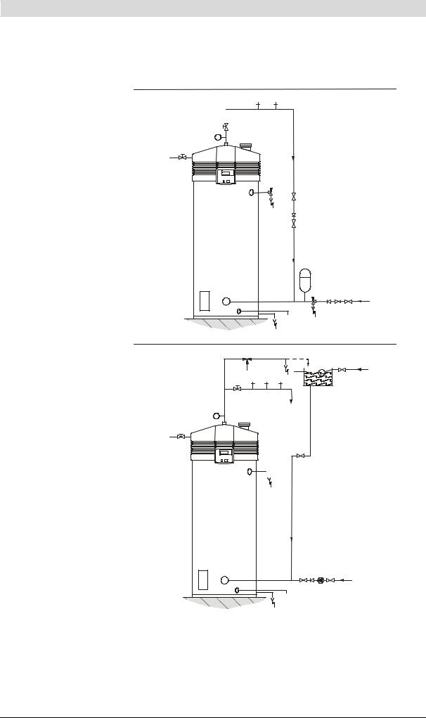
3.5 Installation diagram |
Installation diagram |
Legend
Only applicable numbers are mentioned.
1.pressure reducing valve (mandatory)
3.T&P valve (mandatory)
4.stop valve (recommended in pipe C and mandatory in pipe A)
5.non-return valve (mandatory)
6.circulation pump (optional)
9.drain valve
10.manual gas valve (mandatory)
11.service stop valve
12.temperature gauge (optional)
13.condensation drainage
14.hot water draw-off points
15.expansion valve (mandatory)
16.expansion vessel (mandatory)
17.3-way aeration valve (recommended)
18.water tank
19.float valve
A.cold water supply
B.hot water supply
C.circulation pipe
D.gas supply
E.overflow pipe
H. overflow pipe
UNVENTED |
14 14 14 |
|||
|
|
|
|
|
B 
11
12 T
D 10
3
4
 6
6
5
4
C
16
5 |
1 |
4 |
A |
|
|
|
15
 9
9
13
VENTED |
|
H |
|
|
|
|
|
17 |
E |
19 |
A |
|
14 |
|
4 |
|
|
|
|
11 |
|
18 |
|
|
|
|
|
B |
C |
|
|
|
|
|
|
12 T |
|
|
|
D
10
4
 3
3
4 5 6 4 |
C |
 9
9
13
IMD-0464 R0
Instruction manual BFC |
23 |
3
3.6Water connections, Unvented
3.6.1
Installation |
is |
|
Warning
The installation should be carried out by an authorised installation engineer, in compliance with general and local regulations (1.3 "Regulations").
Cold water side
See (A) in the installation diagram (3.5 "Installation diagram").
1.Fit an approved stop valve (4) on the cold water side as required by applicable regulations (1.3 "Regulations").
2.The maximum working pressure of the appliance is 8 bar. Because the pressure in the water pipe at times can exceed 8 bar, you must fit an approved pressure-reducing valve (1).
3.Fit a non-return valve (5) and an expansion vessel (16).
4.Fit an expansion valve (15) and connect the overflow side to an open wastewater pipe.
3.6.2Hot water side
See (B) in the installation diagram (3.5 "Installation diagram").
Note
Insulating long hot water pipes will prevent unnecessary energy loss.
1.Optional: fit a temperature gauge (12) so you can check the temperature of the tap water.
2.Fit the T&P valve (3).
3.Fit a stop valve (11) in the hot water outlet pipe for servicing.
3.6.3Circulation pipe
See (C) in the installation diagram (3.5 "Installation diagram").
If an immediate flow of hot water is required at draw-off points, a circulation pump can be installed. This improves comfort and reduces water wastage.
1.Fit a circulation pump (6) of the correct capacity for the length and resistance of the circulation system.
2.Fit a non-return valve (5) behind the circulation pump to guarantee the direction of circulation.
3.Fit two stop valves for service purposes (4).
4.Connect the circulation pipe to the cold water supply pipe.
3.6.4Condensation drainage
1.Fit a sloping wastewater pipe to the siphon (13) for condensation drainage and connect this to the wastewater discharge in the boiler room.
Attention
All fittings behind the siphon must be condensation-resistant.
24 |
Instruction manual BFC |

is
3.7Water connections, Vented
Warning
The installation should be carried out by an authorised installation engineer, in compliance with general and local regulations (1.3 "Regulations").
3.7.1Cold water side
See (A) in the installation diagram (3.5 "Installation diagram").
1.Fit an approved stop valve (4) on the cold water side between the cold water head tank (18) and the appliance, as required by
regulations (1.3 "Regulations").
3.7.2Hot water side
See (B) in the installation diagram (3.5 "Installation diagram").
Note
Insulating long hot water pipes prevents unnecessary energy loss.
1.Fit the T&P valve (3).
2.Optional: fit a temperature gauge (12) so you can check the temperature of the tap water.
3.Fit a stop valve (4) in the hot water outlet pipe, for use when servicing.
4.If a circulation pipe is required, continue further by installing the circulation pipe (3.6.3 "Circulation pipe").
3.7.3Circulation pipe
See (C) in the installation diagram (3.5 "Installation diagram").
If an immediate flow of hot water is required at draw-off points, a circulation pump can be installed. This improves comfort and reduces water wastage.
1.Fit a circulation pump (6) of the correct capacity for the length and resistance of the circulation system.
2.Fit a non-return valve (5) behind the circulation pump to guarantee the direction of circulation.
3.Fit two stop valves for service purposes (4).
4.Connect the circulation pipe to the cold water supply pipe.
3.7.4Condensation drainage
1.Fit a sloping wastewater pipe to the siphon (13) for condensation drainage and connect this to the wastewater discharge in the boiler room.
Attention
All fittings behind the siphon must be condensation-resistant.
Instruction manual BFC |
25 |
|
3 |
|
Installation |
is |
|
|
|
||||
3.8 Gas connection |
|
|
|
||
|
|
|
|
||
|
|
Warning |
|
||
|
|
|
|
The installation should be carried out by an authorised installation engineer, |
|
|
|
|
in compliance with general and local regulations (1.3 "Regulations"). |
||
|
|
|
|
|
|
|
|
|
|
|
|
|
|
|
|
Attention |
|
|
|
|
|
Make sure that the diameter and length of the gas supply pipe are large |
|
|
|
|
enough to supply sufficient capacity to the appliance. |
|
|
|
|
|
|
|
|
|
|
|
See (D) in the installation diagram (3.5 "Installation diagram"). |
|
|
|
|
1. |
Fit a manual gas valve (10) in the gas supply pipe. |
|
|
|
|
2. |
Blow the gas pipe clean before use. |
|
|
|
|
3. |
Close the manual gas valve. |
|
|
|
|
4. |
Fit the gas supply pipe to the gas control. |
|
|
Warning
After fitting, check for leaks.
3.9Air supply and flue
3.9.1Introduction
This section covers the following subjects:
•Requirements for flue gas discharge materials
•Concentric connections
•Parallel connections
3.9.2Requirements for flue gas discharge materials
Warning
The installation should be carried out by an authorised installation engineer, in compliance with general and local regulations (1.3 "Regulations").
Depending on the approved installation types, there are several alternatives for connecting the air supply and flue gas discharge.
The appliances are approved for installation types B23, C13, C33, C43, C53 and C63.
The figure and table give information about these appliance types. For an explanation of the possibilities, please contact the manufacturer.
26 |
Instruction manual BFC |

is
Types of appliances
C43 |
B23 |
C33 |
C13 |
|
C53 |
|
|
IMD-0468 R0 |
Instruction manual BFC |
27 |
|
3 |
|
Installation |
|
|
Explanation of type of appliance
is
Type of appliance |
Description |
|
|
|
|
B23 |
Air for combustion is drawn from the boiler room. |
|
|
|
|
C13 |
Concentric and / or parallel wall flue terminal |
|
|
|
|
C33 |
Concentric and / or parallel roof flue terminal |
|
|
|
|
C43 |
Appliances on common air supply and flue gas discharge (concentric and / or |
|
|
|
parallel) in multi-storey building. |
|
|
|
C53 |
Air supply and flue terminal types mixed. |
|
|
|
|
C63 |
Appliances supplied without flue components and / or terminal. These |
|
|
|
appliances must be installed in compliance with local regulations. |
|
|
|
Note
Make sure that the chimney discharges into an area where this is permitted for this category of appliance.
3.9.3 Concentric connections
The table shows the requirements for concentric systems.
Warning
Install flue gas discharge pipe runs with a run-off of 5 mm per metre.
Flue gas discharge requirements for concentric systems (C13, C33)
Appliance |
Diameter |
Maximum length |
Maximum |
|
|
|
number of 90º |
|
|
|
bends |
BFC 28 |
80/125 mm |
40 m |
7 |
|
|
|
|
BFC 30 |
100/150 mm |
40 m |
7 |
|
|
|
|
BFC 50 |
100/150 mm |
40 m |
7 |
|
|
|
|
BFC 60 |
100/150 mm |
15 m |
4 |
|
|
|
|
|
|
|
|
Attention
Both conditions stated in the table must be fulfilled.
Even if there are less bends than the stated maximum, the maximum pipe length may not be exceeded.
Even if the total pipe length is less than the stated maximum, the maximum number of bends may not be exceeded.
The following example illustrates how to use the table.
Practical example of concentric flue gas discharge
Example
The figure shows a BFC 30 installation. The appliance must be fitted with 25 m of concentric pipe (C13/C33) and four 90 degree bends. We need to check whether this configuration complies with the requirements stated in the table.
28 |
Instruction manual BFC |
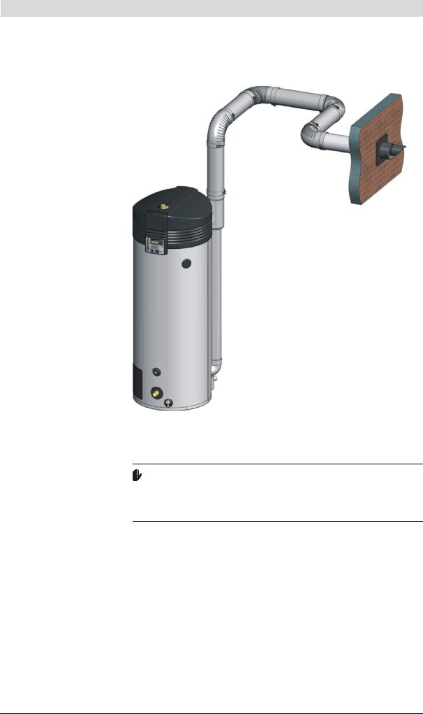
is
Appliance with concentric flue gas discharge material
IMD-0284 R1
According to the table, the maximum length allowed is 40 metres, and there may be up to seven 90 degree bends. Both requirements are fulfilled.
Specifications
Attention
For type C13 and C33 installations,A.O. Smith prescribes the use of a roof or wall-mounted terminal, exclusively of a type approved for the appliance. Use of an incorrect roof or wall-mounted flue terminal can cause the installation to malfunction.
Instruction manual BFC |
29 |

|
3 |
|
Installation |
|
|
is
Concentric wall flue terminal specifications C13
Specification |
|
Description |
|
|
|
|
|
|
|
Wall flue terminal set: |
Art. No. |
BFC 28 |
0302 515 1 |
|
• 1X Wall flue terminal (incl. wall flange |
|
BFC 30-50-60 |
0302 504 1 |
|
|
& clamping ring) |
|
|
|
|
Construction |
Concentric |
|
|
• |
1X Pipe 500mm |
|
||
|
|
|
||
Manufacturer |
Muelink & Grol |
|
||
• |
1X Bend 90° |
|
||
|
|
|
||
Model |
M2000 MDV SEC |
|
||
|
|
|
||
|
|
|
|
|
Pipe material |
Construction |
Concentric |
|
|
|
|
|
|
|
|
|
Flue |
Thick-walled aluminium with lip ring seal |
|
|
|
|
|
|
|
|
Air supply |
Thin-walled galvanised sheet steel |
|
|
|
|
|
|
Pipe diameters |
Flue |
BFC 28 |
Ø 80 mm |
|
|
|
|
BFC 30-50-60 |
Ø 100 mm |
|
|
|
|
|
|
|
Air supply |
BFC 28 |
Ø 125 mm |
|
|
|
BFC 30-50-60 |
Ø 150 mm |
|
|
|
|
|
(1) No other wall flue terminal is permitted. Use this item number to order the wall conduit set from supplier, manufacturer or wholesaler.
Concentric roof flue terminal specifications C33
Specification |
|
Description |
|
|
|
|
|
Roof flue terminal set: |
Art. No. |
BFC 28 |
0305 042 1 |
• 1X Wall flue terminal (incl. clamping |
|
BFC 30-50-60 |
0304 423 1 |
ring) |
|
|
|
Construction |
Concentric |
|
|
• 1X Pipe 1000mm |
|
||
|
|
|
|
Manufacturer |
Muelink & Grol |
|
|
• 1 X Mounting flange |
|
||
|
|
|
|
Model |
M2000 DDV HR-C |
|
|
|
|
||
|
|
|
|
Pipe material |
Construction |
Concentric |
|
|
|
|
|
|
Flue |
Thick-walled aluminium with lip ring seal |
|
|
|
|
|
|
Air supply |
Thin-walled galvanised sheet steel |
|
|
|
|
|
Pipe diameters |
Flue |
BFC 28 |
Ø 80 mm |
|
|
BFC 30-50-60 |
Ø 100 mm |
|
|
|
|
|
Air supply |
BFC 28 |
Ø 125mm |
|
|
BFC 30-50-60 |
Ø 150 mm |
|
|
|
|
(1) No other wall flue terminal is permitted. Use this item number to order the wall conduit set from supplier, manufacturer or wholesaler.
30 |
Instruction manual BFC |
 Loading...