


MODELS COF-199 THRU 700A
COMMERCIAL OIL FIRED WATER HEATER FOR HOT WATER SUPPLY
• Installation • Service • Maintenance
 ASME
ASME 
 CAUTION
TEXTPRINTEDOROUTLINEDINREDCONTAINSINFORMATIONRELATIVE
TO YOUR SAFETY. PLEASE READ THOROUGHLY BEFORE USING
APPLIANCE.
A DIVISION OF A.O. SMITH CORPORATION
MCBEE, SC • SEATTLE, WA
STRATFORD, (ONTARIO) CANADA
VELDHOVEN, THE NETHERLANDS
|
PLACE THESE INSTRUCTIONS ADJACENT TO HEATER AND |
|
NOTIFY OWNER TO KEEP FOR FUTURE REFERENCE. |
PRINTED IN U.S.A. 0705 |
PART NO. 193472-001 |
1
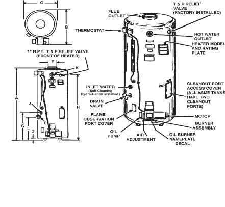
 FEATURES AND SPECIFICATIONS
TEXT PRINTED OR OUTLINED IN RED CONTAINS INFORMATION |
applications. The principal components of the heater are shown and |
|
RELATIVE TO YOUR SAFETY. PLEASE READ THOROUGHLY BEFORE |
identified here. The identification plate illustrations on page 4 interpret |
|
USING APPLIANCE. |
||
certain markings into useful information. Use these references to identify |
||
|
||
This is a typical Duraclad oil-fired heater for commercial water heating |
the heater and its components |
FIGURE 1
TABLE 1 NOMINAL MODEL DIMENSIONS
|
|
Model |
|
|
COF - 199 |
|
COF - 245 |
|
COF - 315/315A |
|
COF - 385/385A |
|
COF - 455/455A |
|
COF - 700/700A |
|
|
||||||||||||||||||||||||||
|
|
Dim. |
|
Inches |
mm |
|
Inches |
mm |
|
Inches |
|
mm |
|
|
Inches |
|
|
mm |
|
Inches |
|
|
mm |
|
Inches |
|
|
mm |
|
|
|||||||||||||
|
|
|
A |
|
74 1/2 |
1,892 |
|
74 1/2 |
1,892 |
|
74 1/2 |
|
1,892 |
|
73 3/4 |
|
|
1,873 |
|
73 3/4 |
|
1,873 |
|
73 3/4 |
|
1,873 |
|
||||||||||||||||
|
|
|
B |
|
36 3/4 |
933 |
|
36 3/4 |
933 |
|
|
36 3/4 |
|
933 |
|
36 3/4 |
|
|
933 |
|
36 3/4 |
|
|
933 |
|
36 3/4 |
|
933 |
|
|
|||||||||||||
|
|
|
C |
|
27 3/4 |
705 |
|
27 3/4 |
705 |
|
|
27 3/4 |
|
705 |
|
27 3/4 |
|
|
705 |
|
27 3/4 |
|
|
705 |
|
27 3/4 |
|
705 |
|
|
|||||||||||||
|
|
|
D |
|
2 |
51 |
|
2 |
51 |
|
|
|
2 |
|
|
51 |
|
2 |
|
|
51 |
|
|
2 |
|
|
51 |
|
2 |
|
51 |
|
|
|
|||||||||
|
|
|
E |
|
|
3/4 NPT |
|
|
3/4 NPT |
|
|
|
3/4 NPT |
|
|
3/4 NPT |
|
|
|
3/4 NPT |
|
3/4 NPT |
|
|
|||||||||||||||||||
|
|
|
F |
|
8 |
203 |
|
8 |
203 |
|
|
|
8 |
|
|
203 |
|
8 |
|
|
203 |
|
|
8 |
|
|
203 |
|
10 |
|
254 |
|
|
||||||||||
|
|
|
G |
|
26 5/8 |
676 |
|
26 5/8 |
676 |
|
|
26 5/8 |
|
676 |
|
24 3/4 |
|
|
629 |
|
24 3/4 |
|
|
629 |
|
30 3/16 |
|
767 |
|
|
|||||||||||||
|
|
|
H |
|
74 1/2 |
1,892 |
|
74 1/2 |
1,892 |
|
74 1/2 |
|
1,892 |
|
73 3/4 |
|
|
1,873 |
|
73 3/4 |
|
1,873 |
|
79 3/16 |
|
2,011 |
|
||||||||||||||||
|
|
|
J |
|
1 1/2 NPT |
|
|
1 1/2 NPT |
|
|
1 1/2 NPT |
|
|
1 1/2 NPT |
|
|
1 1/2 NPT |
|
1 1/2 NPT |
|
|
||||||||||||||||||||||
|
|
|
K |
|
1 1/2 NPT |
|
|
1 1/2 NPT |
|
|
1 1/2 NPT |
|
|
1 1/2 NPT |
|
|
1 1/2 NPT |
|
1 1/2 NPT |
|
|
||||||||||||||||||||||
|
|
|
L |
|
22 3/4 |
578 |
|
22 3/4 |
578 |
|
|
22 3/4 |
|
578 |
|
23 7/16 |
|
595 |
|
23 7/16 |
|
|
595 |
|
28 7/8 |
|
733 |
|
|
||||||||||||||
|
|
Approx. |
|
|
|
|
|
|
|
|
|
|
|
|
|
|
|
|
|
|
|
|
|
|
|
|
|
|
|
|
|
|
|
|
|
|
|
|
|
|
|
|
|
|
|
Shipping |
|
553 |
251 |
|
554 |
252 |
|
|
554 |
|
252 |
|
624 |
|
|
283 |
|
700 |
|
|
318 |
|
739 |
|
335 |
|
|
||||||||||||||
|
Weight STD. |
|
Lbs |
Kg. |
|
Lbs. |
Kg. |
|
Lbs. |
|
Kg. |
|
|
Lbs. |
|
|
Kg. |
|
Lbs. |
|
|
Kg. |
|
Lbs. |
|
|
Kg. |
|
|
||||||||||||||
|
|
Approx. |
|
|
|
|
|
|
|
|
|
|
|
|
|
|
|
|
|
|
|
|
|
|
|
|
|
|
|
|
|
|
|
|
|
|
|
|
|
|
|
|
|
|
|
Shipping |
|
|
|
|
|
|
|
|
|
|
|
657 |
|
298 |
|
742 |
|
|
337 |
|
747 |
|
|
339 |
|
822 |
|
373 |
|
|
|||||||||||
|
Weight ASME |
|
--- |
--- |
|
--- |
--- |
|
|
Lbs. |
|
Kg. |
|
|
Lbs. |
|
|
Kg. |
|
Lbs. |
|
|
Kg. |
|
Lbs. |
|
|
Kg. |
|
|
|||||||||||||
|
|
|
|
|
|
|
|
|
|
|
|
|
|
|
|
|
|
|
|
|
|
|
|
|
|
|
|
|
|
|
|
|
|
|
|
|
|
|
|||||
|
ALL DIMENSIONS IN INCHES/mm |
|
|
|
|
|
|
|
|
|
|
|
|
|
|
|
|
|
|
|
|
|
|
|
|
|
|
|
|
|
|
|
|
|
|
||||||||
|
*Model numbers followed by the suffix "A" indicates the optional A.S.M.E. tank construction. |
|
|
|
|
|
|
|
|
|
|
|
|
|
|
|
|
||||||||||||||||||||||||||
|
|
|
|
|
|
|
|
TABLE 2 RECOVERY CAPACITIES, based on 80% efficiency |
|
|
|
|
|
|
|
|
|
|
|
||||||||||||||||||||||||
|
|
|
|
|
|
TANK |
APPROX |
|
|
|
|
|
|
|
|
|
|
|
U.S Gallons/Hr. and Litres/Hr at TEMPERATURE RISE INDICATED |
||||||||||||||||||||||||
|
|
|
|
|
|
CAPACITY |
EFF. |
F° |
|
|
40F° |
|
50F° |
|
60F° |
|
70F° |
|
|
|
80F° |
|
90F° |
|
100F° |
|
110F° |
120F° |
130F° |
|
140F° |
||||||||||||
Model |
|
Btuh |
|
KW |
U.S.Gal. |
Litres |
% |
C° |
|
22.2C° |
|
27.7C° |
33.3C° |
|
38.8C° |
|
44.4C° |
|
50C° |
|
55.5C° |
|
61.1C° |
66.6C° |
72.2C° |
|
77.7C° |
||||||||||||||||
COF |
|
199,000 |
|
|
86 |
|
|
|
80 |
GPH |
|
477 |
|
381 |
|
|
318 |
|
|
272 |
|
238 |
212 |
|
191 |
|
|
173 |
|
159 |
147 |
|
136 |
||||||||||
199 |
|
|
58 |
|
|
326 |
|
|
|
LPH |
|
1804 |
|
1443 |
|
1203 |
|
|
1031 |
|
902 |
802 |
|
722 |
|
|
656 |
|
601 |
555 |
|
516 |
|||||||||||
COF |
|
245,000 |
|
|
86 |
|
|
|
80 |
GPH |
|
587 |
|
469 |
|
|
391 |
|
|
335 |
|
293 |
261 |
|
235 |
|
|
213 |
|
196 |
181 |
|
168 |
||||||||||
245 |
|
|
72 |
|
|
326 |
|
|
|
LPH |
|
2221 |
|
1777 |
|
1481 |
|
|
1269 |
|
1111 |
987 |
|
889 |
|
|
808 |
|
740 |
683 |
|
635 |
|||||||||||
COF |
|
315,000 |
|
|
84 |
|
|
|
80 |
GPH |
|
754 |
|
604 |
|
|
503 |
|
|
431 |
|
377 |
335 |
|
302 |
|
|
274 |
|
251 |
232 |
|
216 |
||||||||||
315/315A |
|
92 |
|
|
318 |
|
|
|
LPH |
|
2856 |
|
2285 |
|
1904 |
|
1632 |
|
1428 |
1269 |
|
1142 |
|
1039 |
|
952 |
879 |
|
816 |
||||||||||||||
COF |
|
385,000 |
|
|
75 |
|
|
|
80 |
GPH |
|
922 |
|
738 |
|
|
615 |
|
|
527 |
|
461 |
410 |
|
369 |
|
|
335 |
|
307 |
284 |
|
263 |
||||||||||
385/385A |
|
113 |
|
|
284 |
|
|
|
LPH |
|
3491 |
|
2793 |
|
2327 |
|
|
1995 |
|
1745 |
1551 |
|
1396 |
|
1269 |
|
1164 |
1074 |
|
997 |
|||||||||||||
COF |
|
455,000 |
|
|
75 |
|
|
|
80 |
GPH |
|
1090 |
|
872 |
|
|
727 |
|
|
623 |
|
545 |
484 |
|
436 |
|
|
396 |
|
363 |
335 |
|
311 |
||||||||||
455/455A |
|
133 |
|
|
284 |
|
|
|
LPH |
|
4125 |
|
3300 |
|
2750 |
|
|
2357 |
|
2063 |
1833 |
|
1650 |
|
1500 |
|
1375 |
1269 |
|
1179 |
|||||||||||||
COF |
|
700,000 |
|
|
69 |
|
|
|
80 |
GPH |
|
1677 |
|
1341 |
|
1118 |
|
|
958 |
|
838 |
745 |
|
671 |
|
|
610 |
|
559 |
516 |
|
479 |
|||||||||||
700/700A |
|
205 |
|
|
261 |
|
|
|
LPH |
|
6347 |
|
5077 |
|
4231 |
|
|
3627 |
|
3173 |
2821 |
|
2539 |
|
2308 |
|
2116 |
1953 |
|
1813 |
|||||||||||||
*All tanks are tested at 320 psig working pressure.
**Based on No. 2 fuel oil with a heat content of 140,000 Btu's per gallon at 80% thermal efficiency. Above 2,000 altitude, input ratings should be reduced 4% for each 1000' above sea level.
2

TABLE OF CONTENTS
FEATURES AND SPECIFICATIONS ........................................... |
2 |
APPROVALS ............................................................................... |
3 |
IDENTIFICATION |
|
Oil and Burner Nameplate Decal ....................................... |
3 |
Oil Burner Specifications .................................................... |
4 |
SAFETY ....................................................................................... |
4 |
INSTALLATION |
|
Required Ability .................................................................. |
4 |
General ............................................................................... |
4 |
Uncrating ............................................................................ |
4 |
Leveling .............................................................................. |
4 |
Location .............................................................................. |
4-5 |
Clearances ......................................................................... |
5 |
Combustion and Ventilation Air .......................................... |
5 |
Chemical Vapor Corrosion ................................................. |
5-6 |
Flue Gas Venting ................................................................ |
6 |
Vent Connector and Draft Regulator .................................. |
6 |
Water Piping ....................................................................... |
7 |
Closed Water System ........................................................ |
7 |
Drain Valve and Access Panels ......................................... |
7 |
Fuel Systems ..................................................................... |
7-8 |
Burner Installation .............................................................. |
8-9 |
Fuel Pump .......................................................................... |
9 |
Wiring Diagrams ................................................................. |
10 |
OPERATION |
|
General ............................................................................... |
11 |
Filling .................................................................................. |
11 |
Start Up .............................................................................. |
11 |
Water Temperature Control ................................................ |
11 |
High Limit Switch E.C.O. .................................................... |
11-12 |
Burner Certificate (Combustion Test) ............................... |
12 |
Self-Cleaning Eliminator .................................................. |
12 |
Draining ............................................................................. |
12 |
MAINTENANCE |
|
General ............................................................................... |
12 |
Relief Valves ...................................................................... |
12 |
Flushing .............................................................................. |
13 |
Sediment Removal ............................................................. |
13 |
Lime Scale Removal .......................................................... |
13-14 |
Circulating Pump ................................................................ |
14 |
Soot Removal ..................................................................... |
14 |
Vent System ....................................................................... |
14 |
INSTALLATION DIAGRAMS ....................................................... |
15-19 |
CHECKLIST AND SERVICE INFORMATION |
|
Electrical Wiring Replacement ........................................... |
20 |
Not Enough or No Hot Water ............................................. |
20-21 |
Burner Starts - Won't Operate ............................................ |
21 |
Water Too Hot .................................................................... |
21 |
Water Heater Makes Sounds ............................................. |
21 |
Water Leakage is Suspected ............................................. |
21 |
Burner Won't Start .............................................................. |
21 |
Burner Starts But Fails To Run ........................................... |
21 |
Normal Start, But Locks Out On Safety ............................. |
22 |
Safety Primary Control ....................................................... |
22 |
COMBUSTION TEST SPECIFICATIONS .................................... |
22 |
TROUBLESHOOTING ................................................................. |
23 |
WARRANTY ................................................................................. |
24 |
APPROVALS
The burner and controls are listed by Underwriters' Laboratories Inc. Accordingly, the burner bears one of the UL labels indicating periodic inspection of the production of this equipment.
All ASME tanks are built to the standards of Section IV of the American Society of Mechanical Engineers code and are stamped with their symbol. The National Board of Boiler and Pressure Vessel Inspectors papers are furnished upon request. The NB number and HLW symbol (to the right) are on the plate located just below cleanout on tank. (May be viewed by removing cleanout cover on jacket).
|
IDENTIFICATION |
|
|
OILBURNER NAMEPLATE DECAL |
|
The heater and burner rating plates or labels provide valuable information. |
||
When ordering parts or inquiring about a unit, be sure to include all |
The oil burner's nameplate decal (see page 2 for the approximate location |
|||||
information from the plates. See the picture on page 2 for approximate |
||||||
on the burner) contains a burner code 940 or 941 which should exactly match |
||||||
location of the heater rating plate. |
|
|
||||
|
|
the model input appearing under the model number of the heater's rating plate. |
||||
|
|
|
|
|
||
The heater rating plate model number, see fig. 2, includes a series |
If these codes do not match, the oil burner may not be the correct model for |
|||||
number which identifies the construction of the heater. |
||||||
the heater model purchased, Contact your A.O. Smith dealer for further |
||||||
|
|
|
|
|
||
|
|
|
|
|
information and replacement, if required. |
|
COF 455 940 |
CO5MOO6721 XXXXXXXXXX |
|
||||
455,000 |
3.25 |
XXX.X |
XX |
XXX |
|
|
120 |
10 |
60 |
|
|
|
|
A TYPICAL HEATER RATING PLATE |
|
A TYPICAL OIL BURNER NAMEPLATE DECAL |
||||
|
|
FIGURE 2 |
|
|
FIGURE 3 |
|
|
|
|
|
3 |
|
|

OIL BURNER SPECIFICATIONS
The oil burner nameplate decal includes a series code which identifies the major features of the oil burner. The series number is the last three digits of the burner code number.
Table 3 below describes the oil burner characteristics for each series number. The burners are to be used with fuel oil not heavier than No. 2.
TABLE 3 SOME NOTABLE OIL BURNER FEATURES
A.O. Smith |
R.W. |
|
|
Suntec |
Nozzle Type |
|
Burner |
Becket |
Safety |
Oil Pump |
Oil |
|
|
or Heater |
Burner |
Timing |
Type |
Pump |
|
|
Series |
Model |
+ |
Mode |
|
Spray |
Spray |
Number* |
Number |
|
|
|
Pattern |
Angle |
|
|
|
|
A2VA |
|
|
|
AFG |
|
|
7118 |
Type B |
|
940 |
|
15 Sec. |
Single |
- |
Solid |
80° |
|
SF |
|
Stage |
A2YA- |
Cone |
|
|
|
|
|
7916 |
|
|
|
|
|
|
B2VA |
|
|
|
|
|
|
8216 |
Type B |
|
941 |
AFG |
15 Sec. |
Two- |
- |
Solid |
80° |
|
SF |
15 Sec. |
Stage |
BY2A |
Cone |
|
|
|
|
|
8916 |
|
|
*To provide the proper firing rate for each model heater, see SPECIFICATIONS: there are burner models for each heater model in table 2. The Burner and heater model numbers must match and the heater (or the burner) series number should indicate the features specified for the installation.
+All oil burners are UL defined as having "interrupted ignition" . . . meaning the ignition is on during the flame establishing period only. Ignition is off when the burner is off. Standard safety timing is 15 seconds.
The heater series number determines the type of oil pump supplied with the oil burner. For installations where gravity feed of fuel oil from
the storage tank to the heater is practical, an oil burner with a singlestage oil pump can be used. The 940 series of burners have singlestage pumps which are shipped for installation of a supply line to the tank only. A return line back to the storage tank can be installed, if required, by making a small modification to the pump, see the oil burner installation manual.
For installations where gravity feed cannot be employed, (the storage tank is located significantly below, or remote from, the heater) an oil burner with a two-stage oil pump should be used. The 941 series of burners have two-stage pumps which are shipped for installation of a supply and return line to the tank. However, in situations where the return line is not required (low lift installations), the pump may be modified to operate without the line, see the oil burner installation manual.
IMPORTANT
The oil-fired water heater shipment consists of two packages, heater and oil burner. Check to be certain the model number on the heater and oil burner packages match. To assure matching equipment, see preceding information.
|
|
COF |
COF |
COF |
COF |
COF |
COF |
Model Heater |
199 |
245 |
315/315A |
385/385A |
455/455A |
700/700/A |
|
Min. |
A.O. Smith |
|
|
|
|
|
|
Firing |
Burner |
1.42 |
1.75 |
2.25 |
2.75 |
3.25 |
5.0 |
Rate |
|
|
|
|
|
|
|
|
|
|
|
|
|
|
|
In |
Non |
|
|
|
|
|
|
GPH |
A.O. Smith |
1.1 |
1.5 |
2.0 |
2.5 |
3.0 |
4.5 |
|
Burner |
|
|
|
|
|
|
SAFETY
 DANGER
BE SURE TO TURN OFF POWER WHEN WORKING ON OR NEAR THE ELECTRICAL SYSTEM OF THE HEATER. NEVER TOUCH ELECTRICAL COMPONENTSWITHWETHANDSOFWHENSTANDINGINWATER.WHEN
REPLACING FUSES ALWAYS USE THE CORRECT SIZE FOR CIRCUIT.
If it is necessary to reset the safety control, depress red button one time only. If burner does not operate after depressing red button one time, call serviceman.
 INSTALLATION
REQUIRED ABILITY
INSTALLATION OF SERVICE OFTHIS WATER HEATER REQUIRESABILITY
EQUIVALENT TO THAT OF A LICENSED TRADESMAN IN THE FIELD
INVOLVED. PLUMBING, AIR SUPPLY, VENTING , OIL BURNER AND
ELECTRICAL WORK REQUIRED.
GENERAL
The installer should be guided by these instructions, local codes and the following publications.
•Standard for the Installation of Oil Burning Equipment, NFPA
Standard No. 31, Available from National Fire Protection
Association, Batterymarch Park, MA 02269.
•Code for the Installation of Heat Producing Appliances, Available from American Insurance Association, 85 John Street,
New York, NY 10038.
•The National Electrical Code, NFPA No. 70. Availability same as NFPA Standard No. 31.
•In Canada - CAN/CSA-B139 Installation Code for Oil Burning Equipment.
When other than an A.O. Smith burner is used, this instruction manual can be used as a general guide. The burner manufacturer's instructions will have to be consulted on specific questions of wiring, air adjustment, etc.
Do not test the burner or control system before the heater is filled with water. Follow the START-UP procedure in this manual.
UNCRATING
Uncrate the heater by removing the outside mat and top locator. The shipping pallet must be removed from the unit. It may be possible to simply unbolt the base from the pallet and, with the help of two or more persons, work the unit off the pallet. Some units will be too heavy and will require the use of jacks or lifting equipment. Safely remove the pallet and move the unit into position. Be Careful When Moving This Heater. It will tip over easily.
LEVELLING
Install the heater plumb to the ground. If it is necessary to adjust the heater, use metal shims under the channel type skid base.
LOCATION
The water heater should not be installed where the combustion air is contaminated, see COMBUSTIONAND VENTILATING AIR. Temperature in the location must be above 32°F (0°C) and free of combustible dusts and flammable gases or vapors.
For the best installations, the water heater should be located:
1.On a level surface.
•Shim the channel type skid base as necessary If leveling is required.
2.Near a floor drain.
•The heater should be located in an area where leakage of the tank or connections will not result in damage to the area adjacent to the heater or to lower floors of the structure.
•When such locations cannot be avoided, a suitable drain pan should be installed under the heater.
•The pan should be at least two inches deep, have a minimum length and width of at least two inches greater than the diameter of the heater and should be piped to an adequate drain. The pan must not restrict combustion air flow.
4
•The discharge opening of the relief valve should always be piped to an open drain.
•Choose the point of major hot water usage, fuel supply and chimney.
•Try to make hot water and oil piping as short as possible.
•Insulate hot and cold water piping where heat loss and condensation may be a problem.
CLEARANCES
The heater has minimum clearances to combustible material, on a noncombustible floor of: 6 inches (152 mm) from the sides and rear, 24 inches (610 mm) from the front, and 18 inches (457 mm) from the vent connector. These clearances are, as shown in fig. 4A to prevent possible fire hazard conditions.
At least 24" (610 mm) of top clearances are recommended for vertical vent installation.
Allow sufficient room at rear of heater for servicing of T&P relief valve.
At least 24" (610 mm) should be provided at the front of the unit for proper servicing.
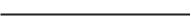
Units which are to be installed on combustible flooring must be supported by a full layer of hollow concrete blocks, fig. 4, from 8" (203 mm) to
12" (305 mm) thick and extending 12" (305 mm) minimum beyond the heater in all directions. The concrete blocks must provide an unbroken concrete surface under the heater, with the hollows running continuous and horizontally. A 3/ 16" (4.8 mm) steel plate must cover the concrete blocks, see fig. 3.
PROPER INSTALLATION ON COMBUSTIBLE FLOORING
FIGURE 4
NOTE: If electrical conduits run under the floor of the proposed heater location, insulate the floor as recommended above.
PROPER INSTALLATION CLEARANCES FOR TWO DIFFERENT
VENTING SYSTEMS
FIGURE 4A
*HOT WATER OUTLET LOCATION AT FRONT OF HEATER
•FACTORY FURNISHED HEATER MANIFOLD KITS (OPTIONAL) ARE DESIGNED FOR 10" (254 mm) SPACING BETWEEN SIDES OF ADJACENT UNITS.
COMBUSTION AND VENTILATION AIR
GENERAL
The water heater area should have sufficient air for satisfactory combustion of oil, and proper venting and of safe ambient temperature.
When a heater is installed in an area where exhaust or ventilating fans may create unsatisfactory combustion or venting, approved provisions must be made to overcome the problem, see NFPA Standard No. 31, Chapter 1.
CHEMICAL VAPOR CORROSION
Water heater corrosion and component failure can be caused by the heating and breakdown of air borne chemical vapors. Spray can propellants, cleaning solvents, refrigerator and air conditioning refrigerants, swimming pool chemicals, calcium and sodium chlorides, waxes, and process chemicals are typical compounds which are potentially corrosive. These materials are corrosive at very low concentration levels with little or no odor to reveal their presence.
Products of this sort should not be stored near the heater. Also, air which is brought in contact with the water heater should not contain any of these chemicals. If necessary, uncontaminated air should be obtained from remote or outside sources.
UNCONFINED SPACES (Building Construction)
NOTE: An uncontaminated space is defined as a space whose volume is not less than 50 ft3 per 1000 BTUH (4.83m3 per kW)of total input of all fuel burning appliances installed in that space. The unconfined space may be thought of as extending to all areas which cannot be separated by a door or door(s). All other spaces not fitting this description, should be thought of as confined space.
1.In unconfined spaces in buildings of conventional frame, brick or stone construction, infiltration will normally supply an adequate amount of air for combustion and ventilation.
2.If the unconfined space is within a building of tight construction, eg. weather stripping, heavy insulation, caulking, vapor barrier, ect., air infiltration may be insufficient to support proper combustion and ventilation, air shall be obtained from outdoors or from spaces freely communicating with the outdoors.
•Follow the instructions under Part 2 of Confined Spaces (Room Construction)
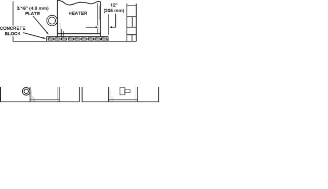
CONFINED SPACES (Room Construction)
1.All air from inside building (conventionally constructed buildings only):
The confined space shall be provided with two permanent openings, one within 12" (305 mm) of the ceiling and one within 12" (305 mm) of the floor, fig. 5.
FIGURE 5
•Each opening shall have a free area of not less than one square inch per 1,000 Btu per hour (140 square inches per gallon of oil consumed per hour) of the total input rating of all appliances in the enclosure, freely communicating with the interior areas having in turn adequate infiltration from the outside. In all cases, each opening shall not have a free area of less than 100 square inches.
2.All Air From Outdoors: The confined space shall be provided with two permanent openings, one in or within 12" of the top of the enclosure and one in or within 12" of the bottom. The openings shall communicate directly, or by means of ducts, with outdoors or such spaces that freely communicate with outdoors.
•If the appliance room is located against an outside wall and the air openings communicate directly with the outdoors, each opening shall have a free area of not less than one square inch per 4,000 Btu per hour (35 square inches per gallon of oil consumed per hour) of the total input rating of all appliances in the enclosure.
5
•When communicating with outdoors by means of vertical ducts, each opening shall have a free area of not less than one square inch per 4,000 Btu per hour (551 mm2/kW) (35 square inches per gallon of oil consumed per hour) of total input rating of all appliances in the enclosure.
•If horizontal ducts are used, each opening shall have a free area of not less than one square inch per 2,000 Btu per hour (1,101 mm 2/kW) (70 square inches per gallon of oil consumed per hour) of total input of all appliances in the enclosure, fig. 6.
TABLE 4 SUGGESTED VENT CONNECTOR SIZES
Model Number |
Outlet Diameter |
|
Inches |
(mm) |
|
COF-199* |
6 |
152.4 |
COF-245 |
8 |
203.2 |
COF-315/315A |
8 |
203.2 |
COF-385/385A |
8 |
203.2 |
COF-455/455A |
8 |
203.2 |
COF-700/700A |
10 |
254 |
*These models are factory supplied with a flue reducer which should be installed on the top cover.
In venting systems where a continuous or intermittent back (positive) draft is found to exist, the cause must be determined and corrected. In some cases, a special vent cap may be required.
If the back draft cannot be corrected by normal methods or if a suitable draft cannot be obtained, additional make up air must be provided to the room to assure proper venting and combustion.
Note: A negative draft must be maintained in the vent piping.
The barometric draft regulator must be installed in the same room as the heater, fig. 6. Locate the regulator as close as possible to the heater and at least 18" (452 mm) from a combustible ceiling or wall. A manually operated damper should not be placed in the chimney connector.
FIGURE 6
FLUE GAS VENTING
In the absence of any local codes, regulations, or vent pipe or chimney manufacturer's recommendations, for oil fired equipment, follow the suggestions below for designing and installing a venting system.
For these water heaters, it is recommended that an adequate chimney be used for venting the flue gases. Type B, double wall, vent pipe should be used as the vent connector pipe. However, where no chimney is available, vent pipe may be used to construct a vent.
Where an existing chimney or vent is to be used, be sure that the chimney or vent has adequate capacity for the number and sizes of appliances being vented through it. Inspect the chimney or vent and remove all soot or other obstructions which will retard free draft.
VENT CONNECTOR AND DRAFT REGULATOR |
CHIMNEY |
PROPER VENT CONNECTOR INSTALLATION
FIGURE 7
The chimney or vent connector diameter should be the same size as the heater flue outlet, see Table 4. A minimum rise of 1/4" per foot (21 mm/M) of horizontal connector length must be maintained between the heater and chimney opening, fig. 7. The connector length should be kept as short as possible.
The oil-fired water heater must be connected to a chimney built in accordance with accepted building code practice or listed factory built type, Table 5. The exit point of the chimney flue gas must be at least 3' (0.91M) above the highest point where it passes through the roof of a building. Also, it must be at least 2' (0.61M) higher than any portion of a building within 10' (3.05 M) of the chimney.
TABLE 5 - USUAL CHIMNEY SIZES FOR UNITS
|
Oil |
|
Equivalent |
Output |
|
Square & Rectangle |
|
|
|
|
|
||||||
|
Firing |
|
Heat Input |
Heat |
|
Stack |
|
Round Stack |
Minimum |
||||||||
Model |
Rate |
|
Rate |
|
Rate |
|
Dimension |
Diameter |
|
Height |
|||||||
Number |
(GPH) |
|
(LPH) |
Btuh |
|
kW |
Btuh |
|
kW |
Inches |
|
mm |
Inches |
mm |
Feet |
|
Metres |
COF-199 |
1.42 |
|
5.38 |
199,000 |
|
58 |
159,200 |
|
47 |
8 1/2 X 8 1/2 |
|
216 x 216 |
9 |
228.6 |
20 |
|
6.1 |
COF-245 |
1.75 |
|
6.62 |
245,000 |
|
72 |
196,000 |
|
57 |
8 1/2 X 8 1/2 |
|
216 x 216 |
9 |
228.6 |
20 |
|
6.1 |
COF-315/315A |
2.25 |
|
8.52 |
315,000 |
|
92 |
252,000 |
|
74 |
8 1/2 X 13 |
|
216 x 330 |
10 |
254 |
30 |
|
9.1 |
COF-385/385A |
2.75 |
|
10.41 |
385,000 |
|
113 |
308,000 |
|
90 |
8 1/2 X 13 |
|
216 x 330 |
10 |
254 |
30 |
|
9.1 |
COF-455/455A |
3.25 |
|
12.30 |
455,000 |
|
133 |
364,000 |
|
107 |
13 X 13 |
|
330 x 330 |
12 |
304.8 |
35 |
|
10.7 |
COF-700/700A |
5.0 |
|
18.93 |
700,000 |
|
205 |
560,000 |
|
164 |
13 X 18 |
|
330 x 457 |
14 |
355.6 |
40 |
|
12.2 |
6
MULTIPLE HEATER FLUES |
DRAIN VALVE AND ACCESS PANELS |
When two or more oil-fired water heaters are connected to a single chimney or vent there shall be sufficient draft available for safe combustion and removal of combustion products to the outdoors from each heater. Refer to local codes for connection details.
Only one oil-fired water heater should be connected to any one type L venting system.
A draft regulator shall be provided for each oil-fired water heater in a multiple heater system.
 DANGER
INCORRECTINSTALLATION CAN CAUSE IMPROPER OPERATION, FIRE,
ASPHYXIATION, SERIOUS PERSONAL INJURY OR DEATH. NEVER
OPERATE THIS WATER HEATER UNLESS IT IS PROPERLY VENTED TO
THE OUTDOORSAND HAS ADEQUATE COMBUSTIONAIR SUPPLY.
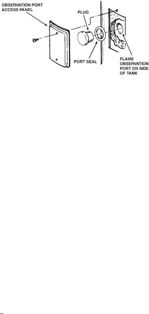
WATER PIPING
GENERAL
The heaters are equipped with a 3/4" NPT drain valve mounted above and to the left of the oil burner, see FEATURES, page 2.
An access panel is located above and to the left of the oil burner and covers the flame observation port, fig. 8. A plug is inserted into the flame observation port and must be removed in order to look into the combustion chamber. Always reinstall plug before replacing access panel.
COMBUSTION CHAMBER ACCESS PORT - FIGURE 8
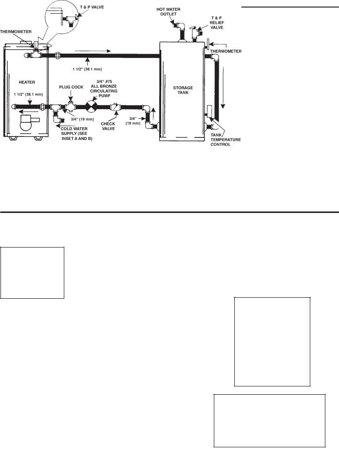
Select the piping diagram for the type of system to be installed from pages 15 through 19. When a circulation pump is used in the system a plug cock should be installed where indicated to regulate water flow through the heater.
RELIEF VALVE
An CSA design-certified and A.S.M.E.-rated temperature and pressure relief valve is installed in the water heater . The relief valve has a discharge capacity exceeding the maximum heater input rating and a pressure rating not exceeding the working pressure shown on the rating plate of the heater.
A temperature and pressure relief valve must also be installed on any potable water storage tank. This relief valve should have a temperature rating of 210° F (98.8°C), a pressure rating not exceeding the lowest rated working pressure of any system component, and a discharge capacity exceeding the total input of the water heaters supplying water to the storage tank.
THE PURPOSE OF A RELIEF VALVE IS TO AVOID EXCESSIVE PRESSURE OR TEMPERATURE INTO THE STEAM RANGE, WHICH
MAY CAUSE SCALDING AT FIXTURES, TANK EXPLOSION, SYSTEM
OR HEATER DAMAGE.
To avoid scalding or water damage, a drain line must be connected to a relief valve to direct discharge to a safe location, A DRAIN LINE MUST NOT BE REDUCED FROM THE SIZE OF THE VALVE OUTLET AND IT MUST NOT CONTAIN ANY VALVES BETWEEN THE HEATER AND THE RELIEF VALVE OR THE RELIEF VALVE AND THE DRAIN LINE EXIT.
IN ADDITION, THERE SHOULD NOT BE ANY RESTRICTIONS IN A DRAIN LINE NOR SHOULD IT BE ROUTED THROUGH AREAS WHERE
FREEZING CONDITIONS MIGHT OCCUR. DO NOT THREAD OR CAP
THE DRAIN LINE EXIT. RESTRICTING OR BLOCKING A DRAIN LINE
WILL DEFEAT THE PURPOSE OF THE RELIEF VALVE AND MAY CREATE AN UNSAFE CONDITION. Install a drain line with a downward slope such that it naturally drains itself.
Your local code authority may have other specific relief valve requirements.
NOTE: These heaters are equipped with an automatic burner shutoff system actuated by high water temperature.
CLOSED WATER SYSTEM
A closed system will exist if a back-flow preventer (check valve), pressure reducing valve, or other similar device is installed in the cold water line between the water heater and the street main (or well). Excessive pressure may develop due to the thermal expansion of heated water causing premature tank failure or intermittent relief valve operation. This type of failure is not covered by the limited warranty. An expansion tank may be necessary in the cold water supply to alleviate this situation, see installation diagrams on pages 15-19. Contact the local plumbing authority.
Another access panel is located above and to the right of the oil burner, fig. 9. This panel covers the cleanout opening in the tank which is sealed by a gasket and cover.
TANK CLEANOUT PORT - FIGURE 9
Models having ASME tank construction will have two cleanout ports. One port will be located as indicated above and the other will be located directly opposite.
Occasionally, some water seepage will occur at a cleanout port. To correct this situation, slightly tighten the cleanout cover bolts until the seepage is eliminated. Do not over tighten the bolts or the cleanout gasket will be damaged. Tighten each bolt gradually and alternate between opposed bolts on the cleanout cover.
FUEL SYSTEMS
GENERAL
The Standard for the Installation of Oil Burning Equipment-NFPA No. 31, local codes, and these instructions must be followed when installing the tank, piping and burner. In addition, an oil pump installation sheet and oil burner certificate are packed with the burner for use and completion by the installer.
On fuel systems with high pressures, a Webster "OSV" oil safety valve
(Webster Electric CO., Racine, Wisc.) will be required to reduce the oil pressure at the burner pump. See FUEL PUMP, page 9, for pressure ratings of the burner's pump.
This manual and the completed oil burner certificate (CS75) are to be left with the user for future reference.
Figure 10 shows a typical single stage one or two line fuel system. When two or more tanks are connected to one burner, the supply line from each tank should run to a header fitted with an approved three-way valve. Normally only one tank may be drawn at a time unless local codes permit simultaneous feeding of two tanks on gravity type installations.
7
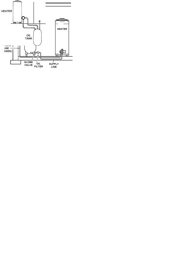
A TYPICAL HEATER INSTALLATION - FIGURE 10
Refer to pages 2, 3, and 4 in this manual for more information about burner series numbers and characteristics for adaptability to the following systems.
SYSTEM TYPES
Single Stage, Supply Line Only: The bottom of the oil storage tank must be above the level of the fuel unit, fig. 11. The fuel oil will flow by gravity to the burner. A single pipe is run between the tank and fuel unit. Burner
Series No. 940 is from this type of service as shipped (the bypass plug is not installed).
TABLE 6
Distance |
Max. |
|
Distance |
Max. |
||
Tank |
Run length |
|
Tank |
Run Length |
||
Bottom |
Ft. (M) |
|
Bottom |
Ft. (M) |
||
Below |
|
|
|
Below |
|
|
|
|
|
|
|
||
Pump |
3/8" |
1/2" |
|
Pump |
3/8" |
1/2" |
Plug |
O.D. |
O.D. |
|
Plug |
O.D. |
O.D. |
Ft. (M) |
Tubing |
Tubing |
|
Ft. (M) |
Tubing |
Tubing |
1 (0.3) |
66 (20.1) |
100 (30.4) |
|
6 (1.8) |
36 (10.9) |
100 (30.4) |
2 (0.6) |
55 (16.7) |
100 (30.4) |
|
7 (2.1) |
31 (9.4) |
100 (30.4) |
3 (0.9) |
50 (15.2) |
100 (30.4) |
|
8 (2.4) |
26 (7.9) |
100 (30.4) |
4 (1.2) |
45 (13.7) |
100 (30.4) |
|
9 (2.7) |
21 (6.4) |
83 (25.2) |
5 (1.5) |
40 (12.1) |
100 (30.4) |
|
10 (3.0) |
16 (4.8) |
64 (19.5) |
Two Stage, Supply and Return Lines: This system, fig. 13, is required when long lines and high lifts (requiring up to 20" of vacuum and 10' vertical lift) are encountered. Burner Series No. 941 is used in this service.
Bypass plug must be installed.
A GRAVITY FEED, SUPPLY LINE ONLY, INSTALLATION
FIGURE 11
If the bottom of the oil tank is at least 2 inches (50.8 mm) higher than the plug opening at which the supply line connects to the fuel pump, a singleline gravity-feed system with 3/8" O.D. tubing may be used with a maximum run length of 100 feet.
•A two stage pump may be used on one line, gravity feed installations. The pump will function as a single stage unit when the by-pass plug is not installed.
•Single Stage, Supply and Return Lines. This type of system, fig. 12, is self-priming. Burner Series No. 940 with by-pass plug field installed, is for this type of service.
If the tank bottom is no lower than 10 feet below the plug, a single stage pump may be used but, it must be a two line system with maximum tubing runs (which includes lift) as shown in Table 6.
A SINGLE STAGE (LOW LIFT), SUPPLY AND RETURN
LINE INSTALLATION - FIGURE 12
A TWO STAGE (HIGH LIFT), SUPPLY AND RETURN
LINE INSTALLATION - FIGURE 13
If the tank(s) bottom is lower than the plug by more than 10 feet, a two stage pump with a two line system must be used with maximum tubing runs (which includes lift) as shown in Table 7.
TABLE 7
Distance |
Max. |
|
Distance |
Max. |
||
Tank |
Run length |
|
Tank |
Run Length |
||
Bottom |
Ft. (M) |
|
Bottom |
Ft. (M) |
||
Below |
|
|
|
Below |
|
|
|
|
|
|
|
||
Pump |
3/8" |
1/2" |
|
Pump |
3/8" |
1/2" |
Plug |
O.D. |
O.D. |
|
Plug |
O.D. |
O.D. |
Ft. (M) |
Tubing |
Tubing |
|
Ft. (M) |
Tubing |
Tubing |
1 (0.3) |
74 (22.5) |
100 (30.4) |
|
9 (2.7) |
51 (15.5) |
100 (30.4) |
2 (0.6) |
71 (21.6) |
100 (30.4) |
|
10 (3.0) |
48 (14.6) |
100 (30.4) |
3 (0.9) |
69 (21.0) |
100 (30.4) |
|
11 (3.3) |
45 (13.7) |
100 (30.4) |
4 (1.2) |
66 (20.1) |
100 (30.4) |
|
12 (3.6) |
42 (12.8) |
100 (30.4) |
5 (1.5) |
63 (19.2) |
100 (30.4) |
|
13 (3.9) |
39 (11.8) |
100 (30.4) |
6 (1.8) |
60 (18.2) |
100 (30.4) |
|
14 (4.2) |
37 (11.2) |
100 (30.4) |
7 (2.1) |
57 (17.3) |
100 (30.4) |
|
15 (4.5) |
34 (10.3) |
100 (30.4) |
8 (2.4) |
54 (16.4) |
100 (30.4) |
|
|
|
|
MULTIPLE HEATER FUEL LINES
Where two or more heaters form a water heating system, each burner shall have an entirely separate oil supply line from the tank to the burner.
BURNER INSTALLATION
GENERAL
An oil Burner Certificate is packed with the oil burner. Following the burner manual installation the necessary tests shall be performed and the results recorded on the certificate, see BURNER CERTIFICATE. The certificate and this instruction manual must be left with the user for future reference.
Check to be certain the heater and burner model numbers are alike and the oil pump characteristics are proper for the job. See IDENTIFICATION, page 3.
8
BURNER
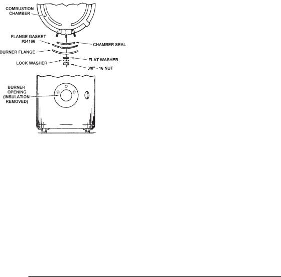
The burner assembly is mounted on the flange of the combustion chamber, fig. 14.
NOTE: Be certain combustion chamber opening is aligned with opening in heater flange, fig. 14, before placing burner into heater .
1.Place the flange gasket over the 3/8" x 1/4" long studs on the flange.
2.Place the burner flange on the studs and into the heater flange opening.
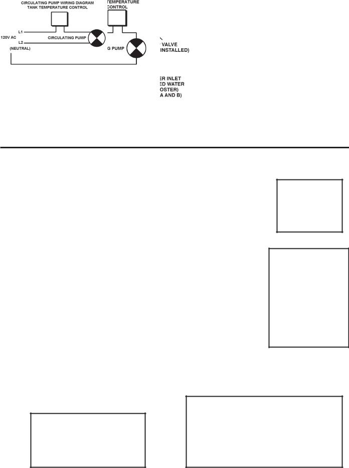
•Bring the factory wiring from the high limit /eco and thermostat into the oil burner junction box.
•Install field and factory wiring as shown in the wiring diagrams, figs. 15. A schematic diagram is also shown for convenience when servicing.
•Ground the heater in accordance with the NEC code to guard against electrical shock from the heater or water system.
3.All burners have "intermittent ignition" as defined by UL (ignition is on during the time the burner is on and off when the burner is off).
4.Do not "test fire" the heater to complete the oil burner certificate until the tank is filled with water, see the oil burner manual.
The certificate and this manual must be left with the user for future reference.
TABLE 8 - OIL PUMP & NOZZLE SPECIFICATIONS
|
Fitting Rate (GPH) |
Oil Burner |
|
Oil Burner |
|
|
|
|
|
||
|
|
|
|
||
|
|
Non |
Pump |
Oil Burner |
Nozzle |
Heater |
State |
State |
Non-Setting |
Nozzle |
Rating |
Model |
Burner |
Burner |
PSIG |
Type |
(GPH) |
COF-199 |
1.42 |
1.1 |
110 |
80ºB |
1.35 |
COF-245 |
1.75 |
1.5 |
100 |
80ºB |
1.75 |
COF-315/315A |
2.25 |
2.0 |
100 |
80ºB |
2.25 |
COF-385/385A |
2.75 |
2.5 |
100 |
80ºB |
2.75 |
COF-455/455A |
3.25 |
3.0 |
100 |
80ºB |
3.25 |
COF-700/700A |
5.00 |
4.5 |
100 |
80ºB |
5.00 |
|
|
|
|
|
|
ASSEMBLY OF THE OIL BURNER TO THE HEATER
FIGURE 14
3.Place the flat washers and lock washers over the studs and fasten the burner in place with the 3/8" - 16 nuts as shown.
Connect the oil line(s) and electrical wires to the burner as follows:
1.The oil pump manufacturer's instructions should be checked for connection and bleeding information.
•The burner is approved for use with fuel oil not heavier than No. 2.
2.An approved, separately fused circuit with disconnect switch should be available for the oil burner. Using Figure 15, the wiring diagram below as a guide:
•Route the 120 volt incoming line in the dual bulb thermostat, mounted on the side of the heater.
FUEL PUMP
GENERAL
All heaters are shipped with the pump pressure set at 100 psig except the COF-199 which is set at 110 psig.
All oil pumps are fitted for installation on single fuel line systems. The pump may be adapted for two line service by using the by-pass Plug and pump manufacturer's instructions packed with the burner.
The single-stage pumps are for single-pipe or two-pipe installations, either lift or gravity feed. On gravity feed installations the inlet pressure is not to exceed 3 psig. On one pipe lift installations the lift is not to exceed 8 ft.
The two-stage pumps are for two-pipe lift installations where the inlet vacuum does not exceed 20" hg. vacuum.
AIR BLEED PROCEDURE (Refer to oil burner manual).
9

FIGURE 15
OPERATION
GENERAL
Never operate the heater unless the tank is filled with water and a temperature and pressure relief valve is installed.
FILLING
1.Oil burner electrical disconnect switch should be in the "OFF" position
2.Close the heater drain valve.
3.Open a nearby hot water faucet to allow the air in the system to escape.
4.Fully open the cold water inlet valve, filling the heater and piping.
5.Close the hot water faucet as water starts to flow from the opening,
Leave the cold water inlet valve fully open. The heater is now ready to start-up if being placed in operation for the first time.
START-UP
The following checks should be made by the installer when the heater is placed into operation for the first time:
1.Check all factory and field made water, oil and electrical connections for tightness. Also check flue gas disposal provisions on top the heater.
•Repair any water and oil leaks. Tighten electrical and flue connections as necessary.
2.Where the water heater or water heating systems includes a circulating pump, it may need to be lubricated before operated. The tube of lubricant supplied with the pump includes directions for use.
•Field installed circulating pumps should be all bronze construction.
Be sure the oil burner, related piping, valves and controls are in place, adjusted and ready for operation before turning on the electricity.
3.Adjust the heater mounted control as follows:
•THERMOSTAT (adjustable) set for desired water temperature.
•It is suggested the thermostat be turned to the lowest setting which satisfies the hot water requirements of the system. This helps minimize scale formation in the heater.
•HIGH LIMIT (not adjustable, manual reset) factory set to cutout at 195° F (90.5°C).
•If the high limit is actuated, the safety primary control will cause the oil burner to shut down. See SAFETY PRIMARY CONTROL, page 21.
•To reset the safety primary control, depress and hold the red button on the control for 30 seconds until the LED flashes twice.
•Depress red button one time only. If burner does not operate after depressing red button one time, call service man.
4.Turn on the oil burner electrical disconnect switch.
5.The heater will begin normal operation on the thermostat's "call for heat".
10
6.To turn the heater off, open the electrical disconnect switch. If the heater is to remain inoperative for a long period of time, close the shutoff valve on the oil supply line.
WATER TEMPERATURE CONTROL
 DANGER
THIS WATER HEATER IS EQUIPPED WITH AN ADJUSTABLE
THERMOSTAT TO CONTROL WATER TEMPERATURE. HOT WATER TEMPERATURES REQUIRED FOR AUTOMATIC DISHWASHER AND
LAUNDRY USE CAN CAUSE SCALD BURNS RESULTING IN
SERIOUS PERSONAL INJURYAND OR DEATH. THE TEMPERATURE
AT WHICH INJURY OCCURS VARIES WITH THE PERSONS AGE
AND TIME OF EXPOSURE. THE SLOWER RESPONSE TIME OF
CHILDREN, AGED OR DISABLED PERSONS INCREASES THE HAZARDS TO THEM. NEVER ALLOW SMALL CHILDREN TO USE
A HOT WATER TAP, OR TO DRAW THEIR OWN BATH WATER.
NEVER LEAVE A CHILD OR DISABLED PERSON UNATTENDED IN A BATHTUB OR SHOWER.
THE WATER HEATER SHOULD BE LOCATED IN AN AREA WHERE
THE GENERAL PUBLIC DOES NOT HAVE ACCESS TO SET
TEMPERATURES.
SETTING THE WATER HEATER TEMPERATUREAT 120°F (48.9°C) WILL REDUCE THE RISK OF SCALDS. Some states require settings at specific lower temperatures.
Figure 16 shows the approximate time-to-burn relationship for normal adult skin. Short repeated heating cycles caused by small hot water uses can cause temperatures at the point of use to exceed the thermostat setting by up to 20°F. If you experience this type of use, you should consider using lower temperature settings to reduce scald hazards.
Temperature |
Time to Produce 2nd & 3rd |
Setting |
Degree Burns on Adult Skin |
180°F (82.2°C) |
Nearly instantaneous |
170°F (76.6°C) |
Nearly instantaneous |
160°F (71.1°C) |
About 1/2 second |
150°F (65.5°C) |
About 1-1/2 seconds |
140°F (60.0°C) |
Less than 5 seconds |
130°F (54.4°C) |
About 30 seconds |
120°F (48.9°C) |
More than 5 minutes |
|
|
|
FIGURE16 |
Valves for reducing point-of-use temperature by mixing cold and hot water are available. Also available are inexpensive devices that attach to faucets to limit hot water temperatures. Contact a licensed plumber or the local plumbing authority.
The water temperature is controlled by a thermostat, fig. 17, which has two sensing elements. One sensor is located near the top of the tank and the other is near the center. The thermostat is set in the lowest position before the heater leaves the factory.
and may be set for 120° (48.9°C) to 180°F (82.2°C) water temperature, but 120°F (48.8°C) is the recommended starting point.
It is suggested the dial be placed in the lowest setting which produces an acceptable hot water supply. This will always give the most energy efficient operation. The temperature control has a 4°F (2.2°C) fixed differential.
HIGH LIMIT SWITCH (E.C.O)
The dual bulb controller (fig.17) contains the high limit (energy cutoff) sensor. The high limit switch interrupts main burner gas flow should the water temperature reach 195°F (90.5°C).
In the event of high limit switch operation, the appliance cannot be restarted unless the water temperature is reduced by 20°F
(11.1°C)(approx.) and the high limit reset button on front of limit control (fig.17) is depressed.
Continued manual resetting of high limit control, preceded by higher than usual water temperature is evidence of high limit switch operation. Contact your dealer or servicer if continued high limit switch operation occurs.
DUAL-BULB THERMOSTAT (COVER REMOVED)
FIGURE17
BURNER CERTIFICATE (COMBUSTION TEST)
The Commercial Standard CS75 Oil Burner Certificate form must be filled in and posted in the vicinity of the water heater.
Instructions for filling in certificate are on the back of the certificate. This must be done by the installer at the time the heater is first operated. The certificate is in the oil burner manual.
SELF-CLEANING ELIMINATOR
These units include a self-cleaning eliminator installed in the front water inlet. See figure 18. The eliminator must be oriented correctly for proper function. There is a marked range on the pipe nipple portion of the eliminator, that must be aligned with the top of the inlet spud. A label above the jacket hole has an arrow that will point to the marked portion of the pipe nipple if the orientation is correct. If the arrow does not point within the marked range on the pipe nipple, adjust the pipe nipple to correct. A pipe union is supplied with the eliminator to reduce the probability of misaligning the eliminator accidentally while tightening the connection to the inlet water supply line. Improper orientation of the eliminator can cause poor performance of the heater and can significantly reduce outlet water temperatures during heavy draws.
The thermostat temperature dial, fig. 17, is accessible by taking off the |
FIGURE18 |
access cover and removing the control cover. The dial is adjustable |
11

DRAINING
The water heater must be drained if it is to be shut down and exposed to freezing temperatures. Maintenance and service procedures may also require draining the heater.
1.Turn off the oil burner electrical disconnect switch.
•If required by the reason for draining the heater, turn off the oil line supply valve.
2.Close the cold water inlet valve to heater.
3.Open a nearby hot water faucet to vent the system.
4.Open the heater drain valve.
5.If the heater is being drained for an extended shutdown, it is suggested the drain valve be left open during this period.
•Follow FILLING instructions when restarting hot water service.
 MAINTENANCE
GENERAL
Water heater maintenance includes periodic tank flushing and cleaning, and removal of lime scale. The oil burner should be inspected and adjusted to maintain proper combustion. Where used, the water heating system circulating pump should be oiled (See table 9).
The depth of lime buildup should be measured periodically. Heaters will have about 2" (50.8 mm) of lime buildup when the level of lime has reached the bottom of the cleanout opening or about 1" of lime buildup if it has reached the drain valve opening. A schedule for deliming should be setup, based on the amount of time it would take for a 1" (25.4 mm) buildup of lime.
Example 1: Initial inspection shows 1/2" (12.7 mm) of lime accumulation. Therefore, the heater can be delimed once a year.
Example 2: Initial inspection shows 2" (50.8 mm) of lime accumulation.
Therefore, the heater should be delimed every 3 months.
Following are the instructions for performing some of the recommended maintenance. Oil burner inspection and adjustment should be performed by a competent technician.
TABLE 9 SUGGESTED MAINTENANCE SCHEDULE
|
|
|
Semi- |
|
Relief Valve |
Lift Lever |
Annually |
|
|
|
|
Flushing |
Monthly |
|
|
|
Sediment |
Semi- |
|
|
|
Removal |
Annually |
|
|
|
Anode |
Semi |
|
Tank |
Inspection |
Annually |
|
|
|
|
Lime Scale |
As |
UN•LIME® |
|
|
Removal |
Required |
Delimer |
Circulating |
|
Four |
SAE No. 20 non-detergent |
|
Pump |
Oiling |
Months |
motor oil |
|
|
|
Inspection |
|
Combustion test |
|
|
and |
Semi- |
kit & test specifications |
Oil Burner |
Adjustment |
Annually |
(Page 26) |
|
|
|
Nozzle |
Semi- |
|
|
|
Replacement |
Annually |
New Nozzle |
Flue Baffle |
|
|
|
|
Pipe |
Cleaning |
Annually |
Wire Brush |
|
Venting |
|
Semi- |
|
|
System |
Inspected |
Annually |
|
|
* Replacement gasket, A.O. Smith Part No. 99038
RELIEF VALVES
At least twice a year, the system relief valves should be checked to ensure that they are in operating condition. To check a relief valve, lift the lever at the end of the valve several times. The valve should seat properly and operate freely.
If water does not flow, remove the valve and inspect for obstructions or corrosion. Replace with a new valve of the recommended size as necessary. Inspection of the valve should be performed at least every three years. Do not attempt to repair the valve, as this could result in improper operating and a tank explosion. In areas with poor water conditions, it may be necessary to inspect the T&P valve more often than twice a year.
 DANGER
BEFORE MANUALLY OPERATING A RELIEF VALVE, MAKE SURE THAT
DRAIN LINE HAS BEEN ATTACHED TO THE VALVE TO DIRECT THE DISCHARGE TOAN OPEN DRAIN. FAILURE TO TAKETHIS PRECAUTION COULD MEAN CONTACT WITH EXTREMELY HOT WATER PASSING OUT OFTHE VALVE DURING THIS CHECK OPERATION.
If the temperature and pressure relief valve on the heater discharges periodically or continuously, it may be due to thermal expansion of water in a closed water supply system, or it may be due to a faulty relief valve.
Thermal expansion is the normal response of water when it is heated. In a closed system, thermal expansion will cause the system pressure to build until the relief valve actuation pressure is equaled. Then, the relief valve will open, allowing water to escape, slightly lowering the pressure.
Your water supplier or local plumbing inspector will know how to best correct this situation. Two common corrections are listed in the Checklist and Service Information which appears later in this manual.
ABOVEALL, DO NOT PLUGTHETEMPERATUREAND PRESSURE RELIEF VALVE. THIS IS NOT A SOLUTION AND CAN CREATE A HAZARDOUS
SITUATION.
FLUSHING
1.Turn off the oil burner electrical disconnect switch.
2.Open the drain valve and allow water to flow until it runs clean.
3.Close the drain valve when finished flushing.
4.Turn on the oil burner electrical disconnect switch.
SEDIMENT REMOVAL
Water borne impurities consist of fine particles of soil and sand which settle out and form a layer of sediment on the bottom of the tank.
For convenience, sediment removal and lime scale removal should be performed at the same time.
LIME SCALE REMOVAL
The amount of calcium carbonate (Lime) released from water is in direct proportion to water temperature and usage, see chart. The higher the water temperature or water usage , the more lime deposits are dropped out of the water. This is the lime scale which forms in pipes, heaters and on cooking utensils.
WATER USAGE IN GALLONS PER DAY POUNDS OF LIME DEPOSITED VS. TEMPERATURE AND WATER USAGE
12
Lime accumulation not only reduces the life of the equipment but also reduces efficiency of the heater and increases fuel consumption.
The usage of water softening equipment greatly reduces the hardness of the water. However, this equipment does not always remove all of the hardness (lime). For this reason it is recommended that a regular schedule for deliming be maintained.
Sediment and lime scale removal may be accomplished through the cleanout opening furnished on the water heater, see FEATURES, page 2. The heater must be drained, see DRAINING, page 12, before removing cleanout cover on tank.
To dissolve and remove the more stubborn mineral deposits, A.O.
Smith UN•LIME® Professional Delimer or equivalent should be used.
A.O. Smith UN•LIME® Delimer is an easy-to-handle patented food grade acid formulated specifically for lime scale removal from all types of water using equipment and is available in 1 gallon (Part No. 4763) and
5 gallon (Part No. 4813) sizes. Hydrochloric base acids are not recommended for use on glass-lined tanks.
A.O. Smith Form No. 4800, entitles Why? When? & How? describes tank cleaning methods and materials. UN•LIME® and booklet may be obtained through your A.O. Smith dealer or distributor.
To clean heater through cleanout opening, proceed as follows:
1.Turn off water inlet valve, the oil burner electrical disconnect switch and open drain valve and allow all water to be drained from heater.
2.Remove outer cover plate from lower side of heater jacket.
3.Remove six (6) hex head screws securing tank cleanout plate and remove plate.
4.Remove lime, scale. or sediment using care not to damage the glass lining.
5.Inspect cleanout plate gasket. If new gasket is required, replace with A.O. Smith Part no. 99038.
6.Install cleanout plate. Be sure to draw plate up tight by tightening screws securely.
7.Close drain valve, open water inlet line and turn on the oil burner electrical disconnect switch.
8.Check for water leakage.
9.Replace outer jacket cover plate.
Flo-jug Method of Deliming
The Flo-Jug is the standard 5 gallon container for UN•LIME® -or- it is available as a deliming kit with UN•LIME®, hose and fittings. Contact your dealer, distributor or the A.O. Smith Water Products Company.
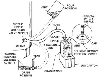
Figure 18 illustrates most of the following steps.
1.The heater should be prepared for deliming as described in the
"Why? When and How" booklet. The relief valve may also be delimed at this time.
2.With the Flow-Jug upright:
•Take off cap, remove cover under opening and install 3/4" x 4" brass pipe nipple.
•Drill or punch a 3/16" vent hole in handle. A stainless steel screw is included with the Flo-Jug kit. This screw is to be installed in the vent hole when Flo-Jug is not in use.
•Remove drain valve from heater and insert a 3/4" x 4" drain nipple.
•Connect the clamp 1" I. D. x 3" hole to Flo-Jug and drain nipple.
3.Lift the Flo-Jug to the POUR POSITION and permit the UN•LIME® to flow into the heater as rapidly as possible.
•Be sure to keep the vent just above the liquid level.
4.Place the Flow-Jug in the DELIME POSITION.
•It may be necessary to place the empty jug on its carton to trap the solution in the heater.
•Allow the UN•LIME® to attack the water scale for 5 minutes.
5.Lower the Flo-Jug to the DRAIN POSITION and allow the UN•LIME® to flow out of the heater as rapidly as possible.
•Observe the vent hole and elevate the jug slightly if there is a possibility of spillage.
•Deliming activity is indicated by foaming on the surface of the solution.
6.Continue the deliming process:
•Raise jug to POUR POSITION. Allow solution to flood into heater.
•Place jug to DELIME POSITION for 5 minutes. Solution is at work in heater.
•Lower jug to DRAIN POSITION and allow solution to flow out. Observe foaming.
DELIMING THE COF WATER HEATER
FIGURE 18
7.After one hour, or earlier if the deliming activity (foaming) stops, inspect the tank interior.
•Drain the UN•LIME® back into jug, DRAIN POSITION, and then stand jug in DELIME POSITION.
•Remove clamp, hose and pipe nipple from heater drain opening.
•Observe interior through opening - a small flashlight works well.
•If the interior still shows water scale, the deliming process should be continued.
•To check UN•LIME® for continued use or reuse, place some lime scale or white chalk into a glass with a small
13
amount of the solution. If the material is vigorously dissolved by the solution, the UN•LIME® can be reused. If not, then UN•LIME® has been weakened and should be replaced.
8.When deliming has been completed, the heater should be flushed for 3 to 5 minutes with fresh water.
•Remove the deliming equipment, install the drain valve, open the cold water inlet line and allow water to flow through heater and out the drain valve. Don't forget to plug vent and cap opening in Flo-Jug.
9.When flushing is completed:
•Fill heater being certain to expel air from tank through a nearby hot water faucet.
•Replace relief valve, removed for deliming.
•Restore oil, water and electrical supply to heater.
•Check for water leakage.
10.Flo-Jug Cleanup.
•Allow scale to separate from UN•LIME® and settle on bottom of Flo-Jug.
•Pour off UN•LIME® into plastic container and check for reuse.
•Rinse sediment from Flo-Jug.
•If UN•LIME® is reusable , pour back into Flo-Jug. Be sure to plug vent and cap opening.
CIRCULATING PUMP
The water heater or water heating system may include a circulating pump. Where used, it may need to be lubricated once every four months with SAE No. 20 non-detergent motor oil or as directed by the manufacturer.
• Place 2 or 3 teaspoons in the bearing oil cup and 10 to 12 drops in the
motor oil cups.
SOOT REMOVAL
Soot must be removed semi-annually from the heater and flow passages to insure efficient operation of the heater.
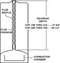
A TYPICAL HEATER FLUEWAY AND FLUE BAFFLE
FIGURE 19
1.Remove chimney connector and top cover of heater from heater. Clean out all soot deposits from connector and chimney opening. A wire brush is recommended for this operation.
2.Remove flue baffles by lifting from tank.
3.Using a wire brush, remove soot from flue passages in heater tank.
CAUTION: While cleaning tank flue passages, care must be taken that brush does not come in contact with the top of the combustion chamber as damage could occur to the combustion chamber lining. Do not allow the brush to enter the heater flue more than noted in fig. 19.
4.Remove oil burner assembly and using a vacuum cleaner, remove all loose soot from combustion chamber area. Avoid contact with combustion chamber as it can be damaged quite easily.
• If flange gasket is damaged, replace with A.O. Smith Part No. 24165
5.Upon completion of cleaning, reassemble the heater. (It may be necessary to apply new sealer tape to the top cover to ensure proper venting. New sealer tape can be ordered from A.O. Smith Water Products Company).
6.Return the heater to operation by following the start-up instructions on page 11.
VENT SYSTEM
Examine the vent system every six months for obstructions and/or deterioration of vent piping. Remove any soot or obstructions and
replace damaged vent piping.
14
INSTALLATION DIAGRAMS
ONE TEMPERATURE - ONE HEATER VERTICAL STORAGE TANK FORCED
CIRCULATION WITH OR WITHOUT BUILDING RECIRCULATION
SCALD PREVENTION
HOT WATER CAN SCALD IF USED
CARELESSLY OR IN UNANTICIPATED
MANNER.
 CAUTION
IF BUILDING COLD WATER SUPPLY HAS
A BACK FLOW PREVENTER, CHECK
VALVE OR WATER METER WITH CHECK
VALVE, PROVISIONS FOR THERMAL
EXPANSION OF WATER IN THE HOT
WATER SYSTEM MUST BE PROVIDED.
NOTE: CONNECT RETURN LINE FROM HOT WATER CIRCULATING LOOP (IF USED) TO COLD WATER INLET LINE.
NOTE:
WHEN USING A A.O.Smith T-140,200,350,OR 400 STORAGE TANK,
USE LOWER 3/4" OPENING FOR TANK TEMP.CONTROL
ONE TEMPERATURE - ONE HEATER HORIZONTAL STORAGE TANK FORCED
CIRCULATION WITH OR WITHOUT BUILDING RECIRCULATION
INSET B |
DANGER: |
TEMPERATURE SETTING SHOULD NOT EXCEED SAFE
TEMPERATURES AT FIXTURES. SEE WATER TEMPERATURE
CONTROL WARNING ON PAGE 11. IF HIGHER PREHEAT
TEMPERATURES ARE NECESSARY TO OBTAIN ADEQUATE
OUTPUT, ADD AN ANTI-SCALD VALVE FOR HOT
SUPPLIED TO FIXTURES.
INSET A
INSTALL THERMAL EXPANSION
TANK IN COLD WATER SUPPLY LINE,
IF CHECK VALVE OR PRESSURE
REDUCING VALVE IS USED IN
SUPPLY.
|
WIRING DIAGRAM FOR HEATER TO TANK LOOP |
* PIPE |
AND /OR HOT WATER LOOP (IF USED) |
INSTALL IN ACCORDANCE WITH LOCAL CODES
15
SINGLE TEMPERATURE OR BOOSTER
 DANGER:
TEMPERATURE SETTING SHOULD NOT EXCEED SAFE
TEMPERATURES AT FIXTURES. SEE WATER TEMPERATURE
CONTROL WARNING ON PAGE 11. IF HIGHER PREHEAT
TEMPERATURES ARE NECESSARY TO OBTAIN ADEQUATE
BOOSTER OUTPUT, ADD AN ANTI-SCALD VALVE FOR HOT
WATER SUPPLIED TO FIXTURES.
TWO TEMPERATURE - ONE HEATER HIGH TEMPERATURE STORAGE
WITH OR WITHOUT RECIRCULATION
INSET B
NOTE: IF TEMPERED WATER IS RECIRCULATED RETURN LINE SHOULD BE CONNECTED AT POINT "A"
* PIPE TO OPEN DRAIN
RETURN LINE FROM 180°F (82.2°C) CIRCULATING LOOP (IF USED)
VACUUM RELIEF VALVE INSTALL PER LOCAL CODES.
INSET A
INSTALL THERMAL EXPANSION TANK IN COLD WATER SUPPLY LINE, IF CHECK VALVE OR PRESSURE REDUCING VALVE IS USED IN SUPPLY.
INSTALL IN ACCORDANCE WITH LOCAL CODES |
WIRING DIAGRAM FOR 180° LOOP (IF USED) |
WIRING DIAGRAM FOR TEMPERED WATER LOOP
(IF USED)
16
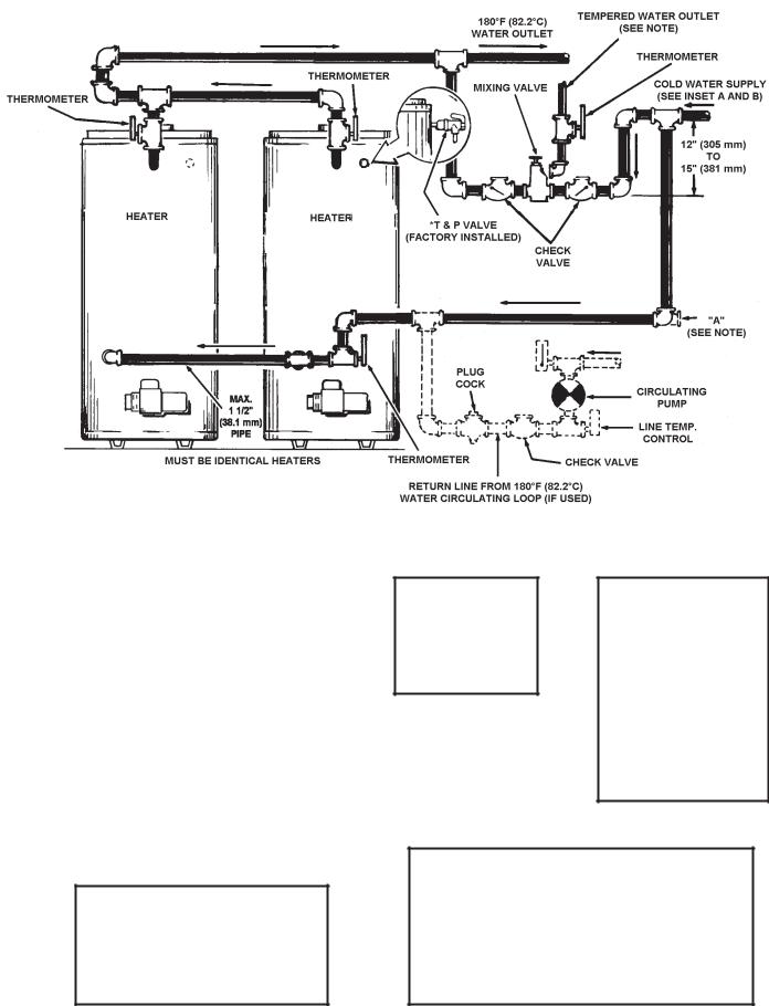
TWO TEMPERTURE - TWO HEATERS HIGH TEMPERATURE STORAGE
WITH OR WITHOUT RECIRCULATION
 DANGER:
TEMPERATURE SETTING SHOULD NOT EXCEED SAFE TEMPERATURES AT FIXTURES. SEE WATER TEMPERATURE CONTROL WARNING ON PAGE 11. IF HIGHER PREHEAT TEMPERATURES ARE NECESSARY TO OBTAIN ADEQUATE BOOSTER OUTPUT, ADD AN ANTI-SCALD VALVE FOR HOT WATER SUPPLIED TO FIXTURES.
* PIPE RELIEF VALVE TO OPEN DRAIN
NOTE: IF TEMPERED WATER IS RECIRCULATED, RETURN LINE SHOULD BE CONNECTED AT POINT "A"
FOR MULTIPLE HEATER INSTALLATION SEE MANIFOLD KIT SPECIFICATIONS, PAGES 22-23
INSTALL IN ACCORDANCE WITH LOCAL CODES
WIRING DIAGRAM FOR TEMPERED WATER LOOP
(IF USED)
INSET B
VACUUM RELIEF VALVE INSTALL PER LOCAL CODES.
INSET A
INSTALL THERMAL EXPANSION TANK IN COLD WATER SUPPLY LINE, IF CHECK VALVE OR PRESSURE REDUCING VALVE IS USED IN SUPPLY.
WIRING DIAGRAM FOR 180° LOOP (IF USED)
17
 Loading...