


New Solution Series
NSK2480
User’s Manual
Manuel de l’utilisateur
Anwenderhandbuch
Manuale per l’operatore
Manual del usuario

At Antec, we continually refine and improve our products to ensure the highest quality. As such, your new case may differ slightly from the description in this manual. This isn’t a problem; it’s simply an improvement. As of the date of publication, all features, descriptions, and illustrations in this manual are correct.
Disclaimer
This manual is intended only as a guide for Antec’s Computer Enclosures. For more comprehensive instructions on installing the motherboard and peripherals, please refer to the user’s manuals that come with those components.
New Solution Series User’s Manual
NSK 2480
Quiet Desktop Case
The Power Supply
NSK 2480 comes with an EarthWatts 380 Watt power supply. This universal input, active PFC, single 80mm fan cooled power supply follows the ATX12V version 2.2 specification, and includes dual +12V output rails that deliver safer and more reliable output to your system’s components. EarthWatts power supplies have achieved 80 PLUS® Certification, the latest independent standard in power supply efficiency, and their higher energy efficiency reduces power consumption by up to 25%, saving you money on your electricity bill. In addition EarthWatts includes a variety of protective circuitry: OPP (over power protection), OVP (over voltage protection), and SCP (short circuit protection).
The PSU comes with a main power switch. Make sure you turn the switch to the ON (I) position before you boot up the computer for the first time. Normally, you won’t need to switch to the OFF (O) position, since the PSU includes a soft on/off feature. This lets you turn the computer on and off by using the soft switch on the computer case. If the computer crashes and you can’t shut it down using the soft switch, you can switch the main power to the OFF (O) position to shut the system down. Then turn the switch back to the ON (I) position and reboot.
Although care has been taken to prevent sharp edges in your Antec case, we strongly recommend taking your time and the appropriate care when working with it. Hurried or careless motion and use of excessive force, particularly when you are working in areas you cannot see clearly, are but a few examples of activity that should be avoided. Please use reasonable precaution.
Setting Up
1.Place the case on a flat, stable surface.
2.Remove the thumbscrews from the back of the top panel. Slide the panel towards the rear to remove it from the case.
3.Inside the case you should see the power supply, some wiring with marked connectors (USB, PWR etc.), an installed I/O panel and a power cord.
The Triple Chamber structure
The case interior is divided into three separate chambers – the power supply chamber, the motherboard chamber and the HDD chamber. This triple chamber structure isolates heat and noise resulting in much quieter and cooler operation
1
than in a traditional desktop case. There are small openings between the chambers to allow for the routing of cables as needed.
Installing the Motherboard
This manual is not designed to cover CPU, RAM, or expansion card installation. Please consult the motherboard manual for specific mounting instructions and troubleshooting.
The motherboard is located inside the main chamber. Two 120mm TriCool™ fans are preinstalled right next to the CPU.
1.Lay the case down so that the open side is up. You should be able to see the drive bay and power supply.
2.Make sure you have the appropriate I/O panel for the motherboard. If the panel provided is not suitable for your motherboard, please contact the motherboard manufacturer for the correct I/O panel.
3.Line up the motherboard with the standoff holes. Determine which holes line up and remember where they are. Not all motherboards will match with all of the provided screw holes, and this is not necessary for proper functionality.
Some standoffs may be pre-installed for your convenience.
4.Lift up and remove the motherboard.
5.Screw in the brass standoffs to the threaded holes that line up with the motherboard.
6.Place the motherboard on the brass standoffs.
7.Screw in the motherboard to the standoffs with the provided Phillips-head screws.
8.The motherboard is now installed.
Connecting the Power and LED
The power supply conforms to the ATX12V Version 2.2 standard. Before you connect the power supply to any of the devices, please consult the appropriate user manuals for the motherboard and other peripherals.
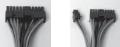
1.Connect the 24-pin Main Power Connector and the 4-pin 12V connector to the motherboard as needed. If the motherboard uses a 20-pin connector; detachthe 4-pin attachment on the 24-pin power connector (see pictures 1 and 2). Note: the detachable 4-pin section of the main power connector cannot be used in place of a 4-pin +12V connector.
Picture 1 |
Picture 2 |
For 24-pin |
For 20-pin |
motherboards |
motherboards |
2.Connect the Reset switch (labeled RESET SW) to the motherboard at the RST connector. Polarity (positive and negative) does not matter for switches.
3.Power Switch (labeled POWER SW) connects to the PWR connector on the motherboard.
4.Power LED connector is a molex connector with blue/white wires. Connect this to any molex connector on the power supply and this will illuminate the circle around the power button when the system is on.
5.Hard Drive LED (labeled HDD LED) connects to the IDE connector. For LEDs, colored wires are positive (+). White or black wires are negative (-). If the LED does not light up when the system is powered on, try reversing the connection. For more info on connecting LEDs to your motherboard, see your motherboard manual.
2
 Loading...