


NINE HUNDRED TWO V3
USER’S MANUAL
Table of Contents |
|
|
Introduction |
|
|
1.1 |
Case Specifications............................................................................................. |
3 |
1.2 |
Diagram.............................................................................................................. |
3 |
Hardware Installation Guide |
|
|
2.1 |
Setting Up .......................................................................................................... |
4 |
2.2 |
Power Supply Installation .................................................................................. |
4 |
2.3 |
Motherboard Installation..………………………………………………… ............................ |
4 |
2.4 |
Flexi-Drive Bay System………….…………………………………………............................... |
5 |
2.5Internal 3.5” Device Installation…………………………………………. ...........................5
2.6 |
External 3.5” Device Installation…………………………………………............................ |
6 |
2.7External 5.25” Device Installation………………………………………. ...........................6
2.8Internal 2.5” Device Installation…………………………………………. ...........................7
2.9Cable Management Compartment……………………………..………............................7
2.10 |
Water Cooling Platform…………………………………………………… .............................. |
8 |
2.11 |
Three-Way SLI Configuration Option…………………………………… .......................... |
8 |
Connecting the Front I/O Ports |
|
|
3.1 |
USB 2.0 Ports………………………………………………….…………… .................................. |
8 |
3.2USB 3.0 Port…………………………………….………………………….. ..................................8
3.3AC’97 / HD Audio Ports……………………….………………………….................................9
3.4Power Switch / Reset Switch / Hard Disk Drive LED Connectors…. ...................9
3.5 |
Rewiring Motherboard Header Connections…………………………… ...................... |
10 |
Cooling System
4.1Big Boy 200 mm TriCool™ Fan………………………………………….. .............................10
4.2Front/Rear TriCool™ LED Fans …………………………………………. .............................11
4.3Optional Fans.………………………………………………………………. .................................12
4.4 |
Washable Air Filters………………………………………..……………… ............................... |
13 |
1
Congratulations on your purchase of the Nine Hundred Two V3!
The best-selling Antec Nine Hundred offers gamers an unbeatable enclosure, one that delivers a combination of cooling, performance and convenience and stands head and shoulders above the competition. The Nine Hundred Two V3 builds on this design, adding a CPU cutout, internal bottommounted 2.5” SSD drive bay and front USB 3.0 port. We know your gaming hardware produces a lot of heat, so we’ve built this case for maximum cooling, with a perforated front bezel, three 120 mm fans with mounts for even more fans and a monster top-mounted 200 mm fan.
The Nine Hundred Two V3 comes without a power supply. Make sure you choose a power supply that is compatible with your computer components and has a long enough power harness to reach your motherboard and peripheral devices. We recommend our High Current Gamer or High Current Pro power supplies for the latest ATX specification compliance, broad compatibility, and power-saving capability.
At Antec, we continually refine and improve our products to ensure the highest quality. It’s possible that your new case will differ slightly from the descriptions in this manual. This isn’t a problem; it’s simply an improvement. As of the date of publication, all features, descriptions, and illustrations in this manual are correct.
Disclaimer: This manual is not designed to cover CPU, RAM, or expansion card installation. Please consult the motherboard manual for specific mounting instructions and troubleshooting. Before proceeding, check the manual for your CPU cooler to find out if there are steps you must take before installing the motherboard. While installing hardware, keep your case on a flat, stable surface.
2

1.1Case Specifications
Case Type |
Mid Tower |
Color |
Black |
|
|
Dimensions |
19.3” (H) x 8.7” (W) x 18.5” (D) |
|
493 mm (H) x 218 mm (W) x 472 mm (D) |
|
|
Weight |
25.4 lbs / 11.5 kg |
Cooling |
1 x Top 200 mm TriCool™ Blue LED 3-speed Fan |
|
2 x Front 120 mm Blue LED Fan with Front Control Knobs |
|
1 x Rear 120 mm TriCool™ Blue LED 3-speed Fan |
|
1 x Side 120 mm Fan Mount (Optional) |
|
1 x Middle 120 mm Fan Mount (Optional) |
Drive Bays |
10 Drive Bays: |
|
- Up to 9 x External 5.25” Drive Bays |
|
- Up to 6 x Internal 3.5” Drive Bays |
|
- 1 x External 3.5” Drive Bay Bracket (Optional) |
|
- 1 Internal bottom-mounted 2.5” SSD drive |
|
|
Expansion Slots |
8 expansion slots to support three-way SLI configuration |
|
|
Motherboard Size |
Mini-ITX, microATX, Standard ATX |
|
|
Front I/O Panel |
2 x USB 2.0 |
|
1 x USB 3.0 |
|
AC’97/HD Audio In and Out |
1.2Diagram
1. 120 mm rear TriCool™ fan |
12 |
2 |
|
|
2.200 mm top TriCool™ fan
3.2 front 120 mm fans with front control knobs
4.1 middle 120 mm fan bracket
5. |
Washable air filters |
1 |
7 |
|
|
||
6. |
Motherboard mount |
3 |
4 |
|
|
|
|
|
– Mini-ITX, microATX or |
|
9/10 |
Standard ATX |
6 |
|
7.CPU cutout
8. |
Power supply mount |
13 |
|
|
|
9. |
9 total 5.25” drive bays |
5 |
10. |
Reconfigurable 3.5” drive |
|
cages |
8 |
|
11. |
Internal 2.5” SSD drive bay |
11 |
|
||
12.Front I/O panel
13.8 expansion slots (Three-way SLI capable)
3
Hardware Installation Guide
2.1Setting Up
1.Place the case upright on a flat, stable surface so that the rear panel (power supply and expansion slots) is facing you.
2.Remove the panel thumbscrews from the side panel and open it by sliding it towards you.
Note: Place the panel thumbscrews carefully aside as they are NOT interchangeable with the HDD cage thumbscrews.
3.Remove the panel thumbscrews from the other side panel and open it by sliding it towards you. Place the screws carefully aside. Inside the case is the power supply mount at the lower rear of the case and the 5.25” drive bay area with two HDD cages inside the bays. You will also find some wiring with marked connectors (USB, PWR etc.), an installed I/O panel and a toolbox containing more hardware (screws, brass standoffs, etc.).
Note: Don’t use your fingernails to pry or lift the panels.
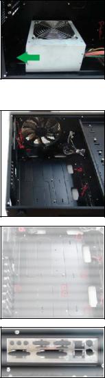
2.2Power Supply Installation
1.With the case upright, place the power supply on the four silicone pads on the bottom of the case.
Note: Power supplies will need to be mounted so that the PSU fan is facing the top of the case.
Nine Hundred Two V3 provides mounting holes for power supplies with standard mounting layouts to be installed upside up or upside down.
2.Push the power supply to the back of the case and align the mounting holes.
3.Attach the power supply to the case with the screws provided.
2.3Motherboard Installation
1.Lay the case down so that the open side is up.
2.Make sure you have the appropriate I/O panel for the motherboard. If the panel provided is not suitable for the motherboard, please contact the motherboard manufacturer for the correct I/O panel.
3.Line up the motherboard with the standoff holes. Determine which holes line up and remember where they are. Not all motherboards will match with all of the provided screw holes, and this is not necessary for proper functionality. Some standoffs may be preinstalled for your convenience.
4
 Loading...