


 Loading...
AMX NI-2000, NXC-ME260-64, NI-2100, NI-3000, NI-4000 User Manual
...WebConsole & Programming Guide
NI Series
NetLinx Integrated Controllers
NI-700/900
NI-2000/3000/4000
NI-2100/3100/4100
NXC-ME260/64
NetLinx Integrated Controllers |
Last Revised: 4/24/2007 |
AMX Limited Warranty and Disclaimer
All products returned to AMX require a Return Material Authorization (RMA) number. The RMA number is obtained from the AMX RMA Department. The RMA number must be clearly marked on the outside of each box. The RMA is valid for a 30-day period. After the 30-day period the RMA will be cancelled. Any shipments received not consistent with the RMA, or after the RMA is cancelled, will be refused. AMX is not responsible for products returned without a valid RMA number.
Warranty Repair Policy
•AMX will repair any defect due to material or workmanship issues during the applicable warranty period at no cost to the AMX Authorized Partner., provided that the AMX Authorized Partner is responsible for in-bound freight and AMX is responsible for out-bound ground freight expenses.
•The AMX Authorized Partner must contact AMX Technical Support to validate the failure before pursuing this service.
•AMX will complete the repair and ship the product within five (5) business days after receipt of the product by AMX. The AMX Authorized Partner will be notified if repair cannot be completed within five (5) business days.
•Products repaired will carry a ninety (90) day warranty or the balance of the remaining warranty, whichever is greater.
•Products that are returned and exhibit signs of damage or unauthorized use will be processed under the Non-Warranty Repair Policy.
•AMX will continue to provide Warranty Repair Services for products discontinued or replaced by a Product Discontinuance Notice.
Non-Warranty Repair Policy
•Products that do not qualify to be repaired under the Warranty Repair Policy due to age of the product or Condition of the product may be repaired utilizing this service.
•The AMX Authorized Partner must contact AMX Technical Support to validate the failure before pursuing this service.
•Non-warranty repair is a billable service.
•Products repaired under this policy will carry a ninety (90) day warranty on material and labor.
•AMX will notify the AMX Authorized Partner with the cost of repair, if cost is greater than the Standard Repair Fee, within five (5) days of receipt.
•The AMX Authorized Partner must provide a Purchase Order or credit card number within five (5) days of notification, or the product will be returned to the AMX Authorized Partner.
•The AMX Authorized Partner will be responsible for in-bound and out-bound freight expenses.
•Products will be repaired within ten (10) business days after AMX Authorized Partner approval is obtained.
•Non-repairable products will be returned to the AMX Authorized Partner with an explanation.
•See AMX Non-Warranty Repair Price List for minimum and Standard Repair Fees and policies.

|
Table of Contents |
Table of Contents |
|
Overview ............................................................................................................ |
1 |
NetLinx Integrated Controllers................................................................................. |
1 |
About This Document ............................................................................................... |
1 |
Related Documents................................................................................................... |
2 |
Quick Setup and Configuration Overview ................................................................ |
2 |
Installation Procedures.................................................................................................... |
2 |
Configuration and Communication.................................................................................. |
2 |
Update the On-board Master and Controller Firmware .................................................. |
3 |
Configure NetLinx Security on the NI Controller ............................................................ |
3 |
Initial Configuration and Firmware Upgrade ...................................................... |
5 |
Before You Start ....................................................................................................... |
5 |
Using the ID Button to Change the Master Device Value ......................................... |
5 |
Obtaining the NI Controller’s IP Address (using DHCP)............................................ |
6 |
Assigning a Static IP to the NI Controller ................................................................. |
8 |
Communicating Via an IP .......................................................................................... |
9 |
Verifying the Firmware Version On the Master ...................................................... |
11 |
Upgrading the On-board Master Firmware via an IP .............................................. |
12 |
Upgrading the NI Controller Firmware Via IP ......................................................... |
14 |
If The Connection Fails .................................................................................................. |
17 |
Upgrading NXC Card Firmware Via IP .................................................................... |
17 |
Resetting the Factory Default System and Device Values ...................................... |
19 |
Onboard WebConsole User Interface ............................................................... |
21 |
WebConsole UI Overview ....................................................................................... |
21 |
Accessing the WebConsole ........................................................................................... |
22 |
Device Tree............................................................................................................. |
22 |
Device Network Settings Pages.............................................................................. |
23 |
WebConsole - WebControl Options ................................................................. |
25 |
Manage WebControl Connections .......................................................................... |
25 |
Compression Options.................................................................................................... |
25 |
WebConsole - Security Options ........................................................................ |
27 |
Security Overview................................................................................................... |
27 |
Default Security Configuration...................................................................................... |
28 |
Login Rules.................................................................................................................... |
28 |
User Name and Password Rules .................................................................................... |
28 |
System Security - System Level............................................................................... |
29 |
System Level Security - System Security Settings ......................................................... |
29 |
NI Series WebConsole & Programming Guide |
i |
|
|

Table of Contents |
|
System Security Access Options .............................................................................. |
30 |
Accepting Changes ....................................................................................................... |
31 |
System Level Security - IPSec Security Settings ............................................................ |
31 |
Configuring Settings ..................................................................................................... |
32 |
Uploading an Configuration File.................................................................................... |
32 |
Managing Certificate Files............................................................................................. |
32 |
AMX IPSec Configuration file ........................................................................................ |
32 |
System Security - Group Level ................................................................................ |
33 |
Adding a New Group .................................................................................................... |
33 |
Group and User Security Access Options ................................................................ |
34 |
Viewing Group Security Settings Details....................................................................... |
36 |
Modifying the Properties of an Existing Group............................................................. |
36 |
Deleting a Group........................................................................................................... |
37 |
System Security - User Level ................................................................................... |
38 |
Adding a New User ....................................................................................................... |
38 |
Viewing and Editing User Security Settings .................................................................. |
39 |
Deleting a User ............................................................................................................. |
39 |
WebConsole - System Options ......................................................................... |
41 |
System Overview .................................................................................................... |
41 |
System - Manage System ........................................................................................ |
41 |
Manage System - System Number .......................................................................... |
42 |
Changing the System Number On the Master............................................................... |
42 |
Using Multiple Netlinx Masters ..................................................................................... |
42 |
Manage System - Control/Emulate Options............................................................ |
42 |
Controlling or Emulating a System Device .................................................................... |
43 |
Manage System - Diagnostics Options.................................................................... |
46 |
Enabling Diagnostics On a Selected System Device...................................................... |
46 |
Diagnostics Options Definitions .................................................................................... |
49 |
Disabling all Diagnostic Options For a Device............................................................... |
50 |
Creating and Recalling Diagnostics Presets................................................................... |
50 |
Manage System - Server Options............................................................................ |
51 |
Port Settings ................................................................................................................. |
51 |
Server Port Settings ...................................................................................................... |
52 |
SSL Certificate Options ................................................................................................. |
53 |
Creating an SSL Server Certificate ................................................................................ |
53 |
SSL Certificate Entries ................................................................................................... |
54 |
Displaying SSL Server Certificate Information............................................................... |
55 |
Creating a Request for an SSL Certificate ..................................................................... |
55 |
Self-Generating an SSL Certificate ................................................................................ |
55 |
Regenerating an SSL Server Certificate Request........................................................... |
55 |
ii |
NI Series WebConsole & Programming Guide |
|
|

|
Table of Contents |
Exporting an SSL Certificate Request ........................................................................... |
56 |
Importing an SSL Certificate ......................................................................................... |
57 |
Manage System - Clock Manager Options.............................................................. |
58 |
Setting the Mode for the Clock Manager ..................................................................... |
58 |
Setting Daylight Savings Rules...................................................................................... |
59 |
Selecting a Custom NIST Server ................................................................................... |
60 |
Adding a Custom NIST Server To the List ..................................................................... |
60 |
Clock Manager NetLinx Programming API.................................................................... |
61 |
System - Manage License........................................................................................ |
61 |
Adding A New License .................................................................................................. |
61 |
Removing a License....................................................................................................... |
62 |
System - Manage NetLinx ....................................................................................... |
63 |
System - Manage Devices ....................................................................................... |
65 |
Manage Devices - Device Options .......................................................................... |
65 |
Configuring Device Binding Options............................................................................. |
65 |
Managing Device Modules............................................................................................ |
66 |
Manage Devices - Bindings..................................................................................... |
67 |
Configuring Application-Defined Devices ..................................................................... |
68 |
Application Devices and Association Status.................................................................. |
69 |
Viewing Physical Device Properties............................................................................... |
70 |
Manage Devices - User-Defined Devices ................................................................ |
71 |
Adding a User-Defined Device...................................................................................... |
71 |
Manage Devices - View All Active Devices ............................................................. |
73 |
Searching For All Compatible Duet Modules for a Selected Device ............................. |
73 |
Viewing Physical Device Properties............................................................................... |
74 |
Manage Devices - Manage Polled Ports.................................................................. |
75 |
Editing Polled Port Settings .......................................................................................... |
75 |
Programming .................................................................................................... |
77 |
Overview ................................................................................................................ |
77 |
Master Send_Commands ........................................................................................ |
77 |
Master IP Local Port Send_Commands ................................................................... |
78 |
LED Disable/Enable Send_Commands .................................................................... |
79 |
Port Assignments By NI Model .................................................................................... |
79 |
RS232/422/485 Ports Channels .............................................................................. |
79 |
RS-232/422/485 Send_Commands ........................................................................ |
80 |
RS-232/422/485 Send_String Escape Sequences.................................................... |
83 |
IR / Serial Ports Channels ....................................................................................... |
84 |
IR RX Port Channels ................................................................................................ |
84 |
IR/Serial Send_Commands ...................................................................................... |
84 |
NI Series WebConsole & Programming Guide |
iii |
|
|

Table of Contents |
|
Input/Output Send_Commands .............................................................................. |
90 |
Terminal (Program Port/Telnet) Commands ..................................................... |
91 |
Overview ................................................................................................................ |
91 |
Establishing a Terminal Connection Via the Program Port...................................... |
91 |
PC COM Port Communication Settings ......................................................................... |
92 |
NetLinx Integrated Controllers - Port Assignments....................................................... |
92 |
Establishing a Terminal Connection Via Telnet ....................................................... |
92 |
Terminal Commands ............................................................................................... |
93 |
ESC Pass Codes ........................................................................................................... |
106 |
Accessing the Security Configuration Options...................................................... |
107 |
Setup Security Menu............................................................................................. |
108 |
Security Options Menu................................................................................................ |
109 |
Edit User Menu............................................................................................................ |
110 |
Edit Group Menu......................................................................................................... |
110 |
Access Rights Menu..................................................................................................... |
111 |
Adding a Group........................................................................................................... |
111 |
Edit Group Menu: Add Directory Association ............................................................. |
112 |
Default Security Configuration .................................................................................... |
113 |
Logging Out of a Terminal Session ....................................................................... |
113 |
Notes on Specific Telnet/Terminal Clients ............................................................ |
114 |
WindowsTM Client Programs ...................................................................................... |
114 |
Linux Telnet Client....................................................................................................... |
114 |
Appendix A: IPSec Configuration File ............................................................. |
115 |
IPSec Config file.................................................................................................... |
115 |
Internet Key Exchange (IKE) ................................................................................. |
116 |
ikeAddPeerAuth ......................................................................................................... |
116 |
ikeSetProp .................................................................................................................. |
118 |
ikeSetPropAttrib ........................................................................................................ |
119 |
Security Policy Database (SPD) ............................................................................. |
120 |
spdAddTransport ....................................................................................................... |
120 |
SpdAddTunnel ............................................................................................................ |
121 |
SpdAddBypass ........................................................................................................... |
122 |
SpdAddDiscard .......................................................................................................... |
123 |
SpdSetProp ................................................................................................................ |
124 |
SpdSetPropAttrib ....................................................................................................... |
128 |
spdSetSA .................................................................................................................... |
129 |
Manual Key Manager (MKM) ................................................................................ |
130 |
mkmAddBypass .......................................................................................................... |
130 |
mkmAddDiscard ......................................................................................................... |
131 |
iv |
NI Series WebConsole & Programming Guide |
|
|

|
Table of Contents |
mkmAddTransport ..................................................................................................... |
132 |
mkmAddTunnel .......................................................................................................... |
133 |
mkmSetInboundAH .................................................................................................... |
134 |
mkmSetInboundESP ................................................................................................... |
135 |
mkmSetOutboundAH ................................................................................................. |
136 |
mkmSetOutboundESP ................................................................................................ |
137 |
Sample IPSec Configuration File ........................................................................... |
138 |
IPSec Web Configuration Interface....................................................................... |
139 |
Appendix B: Clock Manager NetLinx Programming API ................................ |
141 |
Types/Constants ................................................................................................... |
141 |
Library Calls .......................................................................................................... |
142 |
NI Series WebConsole & Programming Guide |
v |
|
|

Table of Contents
vi |
NI Series WebConsole & Programming Guide |
|
|
Overview
Overview
NetLinx Integrated Controllers
NetLinx Integrated Controllers (Masters) can be programmed to control RS-232/422/485, Relay, IR/ Serial, and Input/Output devices using the NetLinx Studio application (version 2.4 or higher).
NetLinx Integrated Controllers
NI-700 |
(FG2105-03) |
NI-900 |
(FG2105-09) |
|
|
|
|
NI-2000 |
(FG2105-01) |
NI-2100 |
(FG2105-04) |
|
|
|
|
NI-3000 |
(FG2105-02) |
NI-3100 |
(FG2105-05) |
|
|
|
|
NI-4000 |
(FG2105) |
NI-4100 |
(FG2105-06) |
|
|
|
|
NXC-ME260/64 (FG2010-64)
These NI Controllers feature an on-board Web Console which allows you to connect to the NI Controller via a web browser and make various configuration and security settings.
The Web Console is described in this document (starting with the Onboard WebConsole User Interface section on page 21).
These NI Controllers are Duet-compatible and can be upgraded via firmware. Duet is a dual-interpreter firmware platform from AMX which combines the proven reliability and power of NetLinx with the extensive capabilities of the Java® MicroEdition (JavaME) platform. Duet simplifies the programming of a system that includes the NI-900 and other third party devices by standardizing device and function definitions, defaulting touch panel button assignments, and controlling feedback methods.
Dynamic Device Discovery makes integration even easier by automatically identifying and communicating with devices which support this new beaconing technology.
Refer to the Manage Devices - Device Options section on page 65 for more detailed information on the use of Dynamic Device Discovery (DDD).
About This Document
This document describes using the on-board Web Console, as well as NetLinx send commands and terminal communications to configure the NI Controllers:
Each major section of the Web Console is described in a separate section of this document.
Refer to:
the Onboard WebConsole User Interface section on page 21,
the WebConsole - WebControl Options section on page 25,
the WebConsole - Security Options section on page 27, and
the WebConsole - System Options section on page 41).
The Initial Configuration and Firmware Upgrade section (page 5) describes upgrading the firmware on NI Controllers.
The Programming section (page 77) lists and defines the NetLinx send commands that are supported by these NI Controllers.
The Terminal (Program Port/Telnet) Commands section (page 91) describes the commands and options available via either a Program Port (RS232) or Telnet terminal session with the NI Controller.
NI Series WebConsole & Programming Guide |
1 |
|
|
Overview
Related Documents
For detailed descriptions of NI Controller hardware, including specifications, port assignments, installation procedures, connection and wiring information, refer to the Hardware Reference Guide for your Master:
Related Documents
Title
NXI-700/900 NetLinx Integrated Controllers - Hardware Reference Guide
NXI-x000 NetLinx Integrated Controllers - Hardware Reference Guide (NI-2000, NI-3000, NI-4000)
NXI-x100 NetLinx Integrated Controllers - Hardware Reference Guide (NI-2100, NI-3100, NI-4100)
NXC-ME260/64 NetLinx Master-Ethernet Card/Module - Hardware Reference Guide
NetLinx CardFrame, Control Cards, and NetModules Instruction Manual
NetLinx Studio v2.4 or higher Instruction Manual
NetLinx Programming Language Reference Guide
All product documentation is available to view or download from www.amx.com.
Quick Setup and Configuration Overview
Installation Procedures
The general steps involved with most common installations of this device include:
Unpack and confirm the contents of box (see the Specifications tables in the Hardware
Reference Guide for each Controller).
Connect all rear panel components and supply power to the NI Controller from the external power supply.
Configuration and Communication
The general steps involved with setting up and communicating with the NI Controllers’ on-board Master. In the initial communication process:
Set the communication speed on the front Configuration DIP switch (default = 38400).
Connect and communicate with the on-board Master via the Program port.
Set the System Value being used with the on-board Master.
Re-assign any Device values.
You can then either get a DHCP Address for the on-board Master or assign a Static IP to the on-board Master.
Once the IP information is determined, rework the parameters for Master Communication in order to connect to the on-board Master via the Ethernet and not the Program port.
2 |
NI Series WebConsole & Programming Guide |
Overview
Update the On-board Master and Controller Firmware
Before using your new NI unit, you must first update your NetLinx Studio to the most recent release.
Upgrade the on-board Master firmware through an IP Address via the Ethernet connector (Upgrading the On-board Master Firmware via an IP section on page 12) (IP recommended).
Upgrade the Integrated Controller firmware through an IP Address via the Ethernet connector (Upgrading the NI Controller Firmware Via IP section on page 14) (IP recommended).
Configure NetLinx Security on the NI Controller
Setup and finalize your NetLinx Security Protocols (WebConsole - Security Options section on page 27).
Program your NI Controller (Programming section on page 77).
NI Series WebConsole & Programming Guide |
3 |
|
|

Overview
4 |
NI Series WebConsole & Programming Guide |

Initial Configuration and Firmware Upgrade
Initial Configuration and Firmware Upgrade
This section describes using the NetLinx Studio software application to perform the initial configuration of the Master, as well as upgrading the firmware for various Master components.
NetLinx Studio is used to setup a System number, obtain/assign the IP/URL for the connected NI Controller, and transfer firmware Kit files to the Master.
NetLinx Studio is available to download (free of charge) from www.amx.com.
Before commencing, verify you are using the latest firmware Kit file (this file contains both the NI Integrated Controller and on-board Master firmware.
The NI-4000/3000/2000 Kit file begins with 2105_X000. The NI-4100/3100/2100 Kit file begins with 2105_04_X100.
The NI-700/900 Kit file begins with 2105_03_NI-X00 and 2105_09_NI-X00 respectively.
Before You Start
1.Verify you have the latest version of NetLinx Studio on your PC. Use the Web Update option in NetLinx Studio’s Help menu to obtain the latest version. Alternatively, go to www.amx.com and login as a Dealer to download the latest version.
2.Verify that an Ethernet/ICSNet cable is connected from the NI Controller to the Ethernet Hub.
3.Connect an programming cable (RS-232) from the Program Port on the NI Controller to a COM port on the PC being used for programming.
4.Verify that any control cards (NI-4000 and NI-4100 only) are inserted and their respective connectors are attached to the rear of the NI Controller before continuing.
5.Verify that the NI Controller is powered On.
Using the ID Button to Change the Master Device Value
The steps described and the dialogs shown in this section are in the NetLinx Studio application.
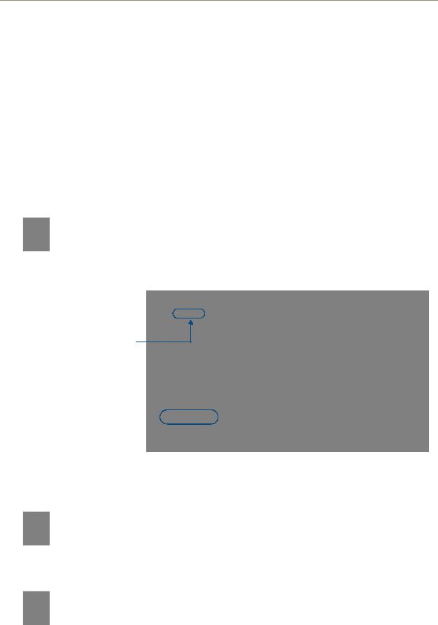
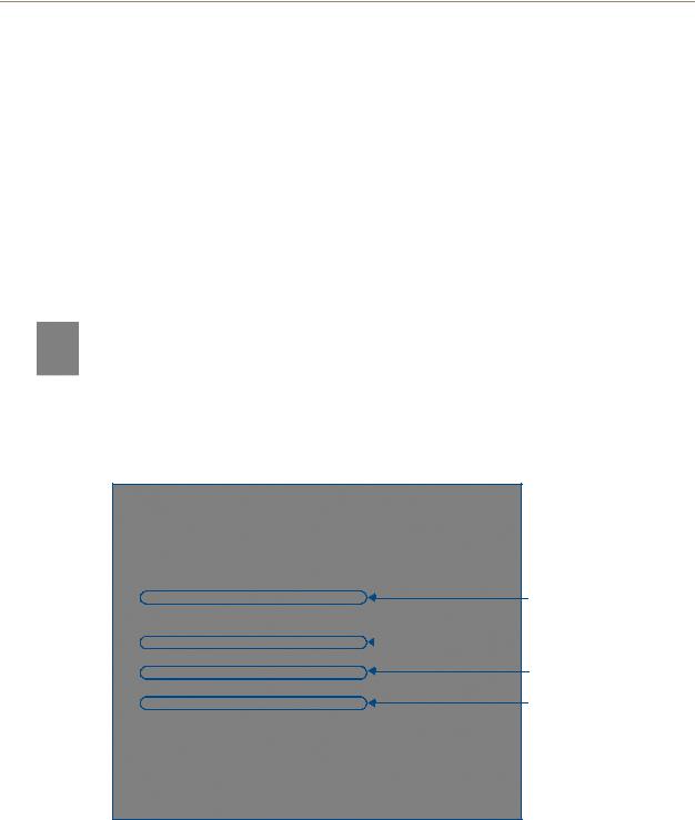
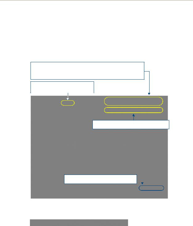
1.Access the Device Addressing dialog (FIG. 1) by selecting Diagnostics > Device Addressing.
Enter the Master’s new Device value
Assign the new value to the Master
A B
FIG. 1 NetLinx Studio: Device Addressing dialog (using the ID mode to set the NI Controller’s device value)
2.In the Device field (A in FIG. 1), enter the new value for the NI Controller (range = 0 - 32767).
3.Press the Start Identify Mode button (B in FIG. 1).
NI Series WebConsole & Programming Guide |
5 |
|
|
Initial Configuration and Firmware Upgrade
This action causes the *Not Active* message (in red) to display a Waiting...Press Cancel to Quit message (in green). This message indicates that Studio is waiting to detect the device value of the NI Controller associated with the ID button.
4.Press the NI Controller’s ID button to read the device value of the NI Controller, and assign it to the new value entered in step 2.
Once the swap has been successfully made, a red Successful Identification Made field appears.
The previous Device and System numbers of the NI Controller are displayed below the red field.
Example: Previous D:S=32002:1,
where 32002 represents the previous device value of the NI Controller (D) and 1 represents the NI Controller’s System value (S).
Obtaining the NI Controller’s IP Address (using DHCP)
Verify there is an active Ethernet connection on the NI Controller’s Ethernet port before beginning these procedures.
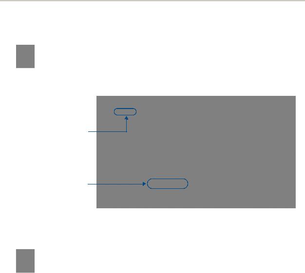
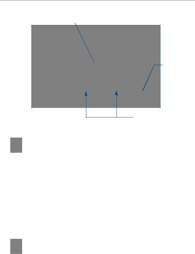
1.In NetLinx Studio, select Diagnostics > Network Addresses from the Main menu to access the Network Addresses dialog (FIG. 2).
System Address reflects the value set in the Device Addressing tab
Used to obtain a 

Dynamic (DHCP)
IP Address
FIG. 2 NetLinx Studio: Network Addresses dialog (for a DHCP IP Address)
2.Verify that both the System number corresponds to the System value previously assigned within the Device Addressing tab and that zero (0) is entered into the Device field.
The system value must correspond to the Device Address entered in the Device Addressing dialog. Refer to the Manage System - System Number section on page 42 for more detailed instructions on setting a system value.
3.Click the Get IP Information button to configure the on-board Master for DHCP usage and then read the IP Address obtained from the DHCP Server.
DO NOT enter ANY IP information at this time; this step only gets the System Master to recognize that it should begin using an obtained DHCP Address.
6 |
NI Series WebConsole & Programming Guide |

Initial Configuration and Firmware Upgrade
4.Note the obtained IP Address (read-only). This information is later entered into the Master Communication Settings dialog and used by NetLinx Studio v 2.x to communicate to the NI Controller via an IP. This address is reserved by the DHCP server and then given to the Master.
If the IP Address field is empty, give the Master a few minutes to negotiate a DHCP Address with the DHCP Server, and try again. The DHCP Server can take anywhere from a few seconds to a few minutes to provide the Master with an IP Address.
5.Verify that NetLinx appears in the Host Name field (if not, then enter it in at this time).
6.Click the Use DHCP radio button from the IP Address section.
7.Click the Set IP Information button to retain the IP Address from the DHCP server and assign it to the on-board Master. A popup window then appears to notify you that Setting the IP information was successful and it is recommended that the Master be rebooted.
8.Click OK to accept the change to the new IP/DNS information.
9.Click the Reboot Master button and select Yes to close the Network Addresses dialog.
10.Click Reboot (from the Tools > Reboot the Master Controller dialog) and wait for the System Master to reboot and retain the newly obtained DHCP Address.
The STATUS and OUTPUT LEDs should begin to alternately blink during the incorporation. Wait until the STATUS LED is the only LED to blink.
11.Press Done once until the Master Reboot Status field reads *Reboot of System Complete*.
Verify that these IP values are also entered into the related fields within either the IP Settings section of the System Connection page (on the touch panel) or within the Address field on the web browser.
12.Complete the communication process by continuing on to the Communicating Via an IP section on page 9.
NI Series WebConsole & Programming Guide |
7 |
|
|
Initial Configuration and Firmware Upgrade
Assigning a Static IP to the NI Controller
Verify there is an active Ethernet connection on the Ethernet port of the Master before beginning these procedures.
1.In NetLinx Studio, select Diagnostics > Network Addresses from the Main menu to access the Network Addresses dialog (FIG. 3).
System Address reflects the value set in the Device Addressing tab
Used to retain an
IP Address
FIG. 3 Network Addresses dialog (for a pre-obtained Static IP Address)
2.Verify that both the System number corresponds to the System value previously assigned within the Device Addressing tab and that zero (0) is entered into the Device field.
The system value must correspond to the Device Address previously entered in the Device Addressing tab. Refer to the Manage System - System Number section on page 42 for more detailed instructions on setting a system value.
3.Click the Get IP Information button to temporarily configure the on-board Master for DHCP usage and then read the IP Address obtained from the DHCP Server.
4.Click the Specify IP Address radio button from the IP Address section. With this action, all IP fields become editable.
5.Verify that NetLinx appears in the Host Name field (if not, then enter it in at this time).
6.Enter the IP Address, Subnet Mask, and Gateway information into their respective fields.
7.Click the Set IP Information button to cause the on-board Master to retain this new IP Address (pre-obtained from the System Administrator).
8.Click OK to accept the change to the new IP/DNS information.
9.Click the Reboot Master button and select Yes to close the Network Addresses dialog.
10.Click Reboot (from the Tools > Reboot the Master Controller dialog) and wait for the System Master to reboot and retain the newly obtained DHCP Address.
The STATUS and OUTPUT LEDs should begin to alternately blink during the incorporation. Wait until the STATUS LED is the only LED to blink.
11.Press Done once until the Master Reboot Status field reads *Reboot of System Complete*.
8 |
NI Series WebConsole & Programming Guide |

Initial Configuration and Firmware Upgrade
Verify that these IP values are also entered into the related fields within either the IP Settings section of the System Connection page (on the touch panel) or within the Address field on the web browser.
12.Complete the communication process by continuing on to the Communicating Via an IP section on page 9.
Communicating Via an IP
Whether the on-board Master’s IP Address was Static Set (via the Set IP Info command) or Dynamically obtained (via the Get IP Info command), use the IP Address information from the Network Addresses dialog to establish communication via the Ethernet-connected Master.
1.Use NetLinx Studio to obtain the IP Address of the NI Controller from your System Administrator.
If you do not have an IP Address:
Follow the steps outlined in either the Obtaining the NI Controller’s IP Address (using DHCP) section on page 6,
or the Assigning a Static IP to the NI Controller section on page 8.
2.Select Settings > Master Communication Settings from the Main menu to open the Master Communication Settings dialog (FIG. 4).
FIG. 4 Assigning Master Communication Settings and TCP/IP Settings
3.Click the Communications Settings button to open the Communications Settings dialog.
4.Click on the NetLinx Master radio button (from the Platform Selection section) to indicate you are working with a NetLinx Master (such as the NXC-ME260/64 or NI-Series of Integrated Controllers).
5.Click on the TCP/IP radio button (from the Transport Connection Option section) to indicate you are connecting to the Master via an IP Address.
NI Series WebConsole & Programming Guide |
9 |
|
|

Initial Configuration and Firmware Upgrade
6.Click the Edit Settings button (on the Communications Settings dialog) to open the TCP/IP Settings dialog (FIG. 4). This dialog contains a series of previously entered IP Address/URLs and their associated names, all of which are stored within Studio and are user-editable.
7.Click the New button to open the New TCP/IP Settings dialog where you can enter both a previously obtained DHCP or Static IP Address and an associated description for the connection into their respective fields.
8.Place a checkmark within the Automatically Ping the Master Controller to ensure availability radio box to make sure the Master is initially responding online before establishing full communication.
9.Click OK to close the current New TCP/IP Settings dialog and return to the previous TCP/IP Settings dialog where you must locate your new entry within the List of Addresses section.
10.Click the Select button to make that the currently used IP Address communication parameter.
11.Click OK to return to the Communications Settings dialog and place a checkmark within the Authentication Required radio box if your Master has been previously secured with a username/ password.
12.Click on the Authentication Required radio box (if the Master is secured) and then press the User Name and Password button to open the Master Controller User Name and Password dialog.
13.Within this dialog, you must enter a previously configured username and password (with sufficient rights) before being able to successfully connect to the Master.
14.Click OK to save your newly entered information and return to the previous Communication Settings dialog where you must click OK again to begin the communication process to your Master.
If you are currently connected to the assigned Master, a popup asks whether you would want to temporarily stop communication to the Master and apply the new settings.
15.Click Yes to interrupt the current communication from the Master and apply the new settings.
16.Once the particular System Master is configured for communication via an IP Address, remove the DB9 connector from the Program port on the NI on-board Master.
17.Click Reboot (from the Tools > Reboot the Master Controller dialog) and wait for the Master to reboot.
The STATUS and OUTPUT LEDs should begin to alternately blink during the incorporation. Wait until the STATUS LED is the only LED to blink.
18.Press Done once until the Master Reboot Status field reads *Reboot of System Complete*.
19.Click the OnLine Tree tab in the Workspace window to view the devices on the System. The default System value is one (1).
20.Right-click the associated System number and select Refresh System. This establishes a new connection to the specified System and populates the list with devices on that system. The communication method is then highlighted in green on the bottom of the NetLinx Studio window.
If the connection fails to establish, a Connection Failed dialog appears. Try selecting a different IP Address if communication fails.
Press the Retry button to reconnect using the same communication parameters. Press the Change button to alter your communication parameters and repeat steps 4 thru 18.
10 |
NI Series WebConsole & Programming Guide |
Initial Configuration and Firmware Upgrade
Verifying the Firmware Version On the Master
All NI Controllers contain both an on-board NI Master and an Integrated Controller. If you are using an NI-4000 or NI-4100 with installed NXC cards, these will also show up within the Online Tree tab.
The on-board Master shows up within the Online Tree as 00000 NI Master
The Integrated Controller of the NI shows up as 0XXXX NI-XXXX (ex: 050001 NI-700)
Each of these components has its own corresponding firmware shown in parenthesis ().
1.After Studio has established a connection with the target Master, click on the OnLine Tree tab in the Workspace window to view the devices on the System. The default System value is one (1).
2.Right-click the associated System number and select Refresh System. This establishes a new connection to the specified System and populates the list with devices on that system. The communication method is highlighted in green on the bottom of the NetLinx Studio window.
The current installed firmware version of the on-board NI Master is displayed to the right of the device within the Online Tree tab as 00000 NI Master.
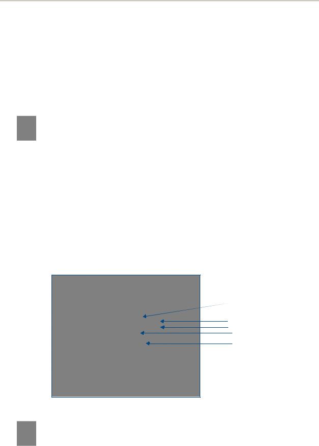
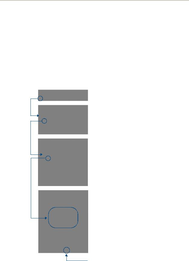
3.After the Communication Verification dialog indicates active communication between the PC and the Master, verify the NetLinx Master (00000 NI Master) appears within the OnLine Tree tab of the Workspace window (FIG. 5).
The default NI Master value is zero (00000) and cannot be changed.
On-board NI Master

 Control cards (NI-4x00 ONLY)
 NetLinx Integrated Controller
NetLinx Studio version
Unbound Dynamic Device
FIG. 5 Sample NetLinx Workspace window (showing OnLine Tree tab)
4.If either the on-board NI Master or Integrated Controller is not the latest firmware version, follow the procedures outlined in the following sections to obtain these Kit files from www.amx.com and then transfer the new firmware Kit files to the device.
NI Series WebConsole & Programming Guide |
11 |
|
|

Initial Configuration and Firmware Upgrade
Upgrading the On-board Master Firmware via an IP
The on-board Master firmware Kit file is not the same as the Integrated Controller Kit file. Below is a table outlining the current sets of on-board Master and Integrated Controller Kit files used by the NISeries of products:
Firmware Kit File usage for NI Controllers
NI-4100 |
On-board Master Kit file: 2105_04_NI-X100_Master |
|
|
|
Integrated Controller Kit file: 2105_04_NI-X100 |
|
|
NI-3100 |
On-board Master Kit file: 2105_04_NI-X100_Master |
|
|
|
Integrated Controller Kit file: 2105_04_NI-X100 |
|
|
NI-2100 |
On-board Master Kit file: 2105_04_NI-X100_Master |
|
|
|
Integrated Controller Kit file: 2105_04_NI-X100 |
|
|
NI-4000 |
On-board Master Kit file: 2105_NI-X000_Master |
|
|
|
Integrated Controller Kit file: 2105_NI-X000 |
|
|
NI-3000 |
On-board Master Kit file: 2105_NI-X000_Master |
|
|
|
Integrated Controller Kit file: 2105_NI-X000 |
|
|
NI-2000 |
On-board Master Kit file: 2105_NI-X000_Master |
|
|
|
Integrated Controller Kit file: 2105_NI-X000 |
|
|
NI-700 |
On-board Master Kit file: 2105-03_NI-X000_Master |
|
|
|
Integrated Controller Kit file: 2105-03_NI_X00 |
|
|
NI-900 |
On-board Master Kit file: 2105-03_NI-X000_Master |
|
Integrated Controller Kit file: 2105-09_NI_X00 |
|
|
Only Master firmware Kit files use the word _Master in the Kit file name.
1.Follow the procedures outlined within the Communicating Via an IP section on page 9 to connect to the target NI device via the web.
2.After NetLinx Studio has established a connection to the target Master, click the OnLine Tree tab of the Workspace window to view the devices on the System. The default System value is one (1).
3.Right-click the associated System number and select Refresh System. This establishes a new connection to the specified System and populates the list with devices on that system. The communication method is highlighted in green on the bottom of the NetLinx Studio window.
4.After the Communication Verification dialog window verifies active communication between the PC and the Master, verify the NetLinx Master (00000 NI Master) appears in the OnLine Tree tab of the Workspace window. The default NI Master value is zero (00000).
First upgrade of the on-board Master using the Master’s Kit file.
The Integrated Controller can later be upgraded using the Controller’s Kit file.
BOTH Kits should be used when upgrading any firmware associated with the
Integrated Controllers.
5.If the on-board Master firmware being used is not current, download the latest Kit file by first logging in to www.amx.com and then navigating to Tech Center > Firmware Files, where you can locate the desired file from within the NetLinx section of the web page.
6.Click on the desired Kit file link and after you’ve accepted the Licensing Agreement, verify you have downloaded the correct NI Master firmware (Kit) file to a known location.
12 |
NI Series WebConsole & Programming Guide |
Initial Configuration and Firmware Upgrade
7.In NetLinx Studio, select Tools > Firmware Transfers > Send to NetLinx Device to open the Send to NetLinx Device dialog (FIG. 6). Verify the target’s System number matches the value listed within the active System folder in the OnLine Tree tab of the Workspace.
The Device number is always 0 for the NI Master.
Selected Master firmware file
Description field for selected Kit file
Firmware download status
Device and System Number
must match the Device and System values listed in the Workspace window
FIG. 6 Send to NetLinx Device dialog (showing on-board NI_Master firmware update via IP)
8.Select the NI Master’s Kit file from the Files section (FIG. 6).
The Kit file for the NI-2000/3000/4000 Masters begins with 2105_NI-X000_Master. The Kit file for the NI-2100/3100/4100 Masters begins with 2105_04_NI-X100_Master. The Kit file for the NI-700/900 Masters begins with 2105-03_NI-X000_Master.
Do not use the 2105-03_NI_Master Kit file on anything other than an NI-700/900, since each Master Kit file is specifically configured to function on a specific NI unit.
9.Enter the System number associated with the target Master (listed in the OnLine Tree tab of the Workspace window) and verify the Device number value. The Port field is disabled.
10.Click the Reboot Device checkbox to reboot the NI unit after the firmware update process is complete.
11.Click Send to begin the transfer. The file transfer progress is indicated on the bottom-right of the dialog (FIG. 6).
NI Series WebConsole & Programming Guide |
13 |
|
|

Initial Configuration and Firmware Upgrade
Only upon the initial installation of a new Kit file to an on-board Master will there be a error message displayed indicating a failure of the last component to successfully download.
This is part of the NI Master update procedure and requires that the firmware be reloaded after a reboot of the unit. This consecutive process installs the final component of the new Kit file.
12.After the last components fails to install, click Done.
13.Click Reboot (from the Tools > Reboot the Master Controller dialog) and wait for the System Master to reboot.
The STATUS and OUTPUT LEDs should begin to alternately blink during the incorporation. Wait until the STATUS LED is the only LED to blink.
14.Press Done once until the Master Reboot Status field reads *Reboot of System Complete*.
15.Repeat steps 5 - 9 again (the last component will now successfully be installed).
16.Click Close once the download process is complete.
The OUTPUT and INPUT LEDs alternately blink to indicate the on-board Master is incorporating the new firmware. Allow the Master 20 - 30 seconds to reboot and fully restart.
17.Right-click the System number and select Refresh System. This establishes a new connection to the System and populates the list with the current devices (and their firmware versions) on your system.
Upgrading the NI Controller Firmware Via IP
1.Follow the procedures outlined within the Communicating Via an IP section on page 9 to connect to the target NI device via the web.
2.After Studio has established a connection to the target Master, click the OnLine Tree tab of the Workspace window to view the devices on the System. The default System value is one (1).
3.Right-click the associated System number and select Refresh System. This establishes a new connection to the specified System and populates the list with devices on that system. The communication method is highlighted in green on the bottom of the NetLinx Studio window.
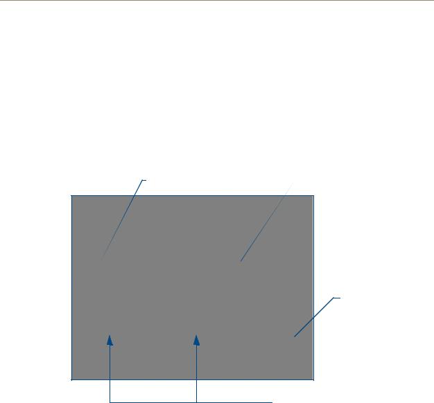
4.After the Communication Verification dialog window verifies active communication between the PC and the NI unit, verify the Integrated Controller appears in the OnLine Tree tab (FIG. 7) of the Workspace window (ex: NI-4000 or NI-700). This entry is different than the NI Master which uses a device value of 00000 (see below):
14 |
NI Series WebConsole & Programming Guide |

Initial Configuration and Firmware Upgrade
On-board NI Master

 (NI-X000_Master) - Device 0
 On-board Integrated Controller (NI-X000)
NetLinx Studio version

 Unbound Dynamic Device
FIG. 7 Sample NetLinx Workspace window (showing separate NI-Master and Controller)
5.If the NI Controller firmware being used is not current, download the latest Kit file by first logging in to www.amx.com and then navigating to Tech Center > Firmware Files, where you can locate the desired file from within the NI Series Device (Integrated Controller) section of the web page.
6.Click on the desired Kit file link and after you’ve accepted the Licensing Agreement, verify you have downloaded the Integrated Controller firmware (Kit) file to a known location.
7.From within Studio, select Tools > Firmware Transfers > Send to NetLinx Device from the Main menu to open the Send to NetLinx Device dialog (FIG. 8). Verify the target’s System number matches the value listed within the active System folder in the OnLine Tree tab of the Workspace.
The Device must match the entry for the on-board Integrated Controller (ex: NI-4000 or NI-700) device.
NI Series WebConsole & Programming Guide |
15 |
|
|
Initial Configuration and Firmware Upgrade
Selected on-board Integrated Controller firmware file
Firmware download status
Device and System Number must match the Device and System
values listed in the Workspace window
FIG. 8 Send to NetLinx Device dialog (showing on-board Integrated Controller firmware update via IP)
The Kit file for the Integrated Controller on the NI-2000/3000/4000 begins with
2105_NI_X000.
The Kit file for the Integrated Controller on the NI-2100/3100/4100 begins with
2105_04_NI_X100.
The Kit file for the NI-700/900 Series begins with 2105-03_NI_X000
Do not use the 2105-03_NI_X00 Kit file on anything other than an NI-700/900 since each Kit file is specifically configured to function on a specific NI unit.
8.Select the Integrated Controller’s (_X00) from the Files section (FIG. 8).
9.Enter the System and Device numbers associated with the target Master (listed in the Workspace window). The Port field is greyed-out.
10.Click the Reboot Device checkbox to reboot the NI unit after the firmware update process is complete.
11.Click Send to begin the transfer. The file transfer progress is indicated on the bottom-right of the dialog (FIG. 8).
12.Click Close once the download process is complete.
The OUTPUT and INPUT LEDs alternately blink to indicate the unit is incorporating the new firmware. Allow the unit 20 - 30 seconds to reboot and fully restart.
13.Right-click the System number and select Refresh System. This establishes a new connection to the System and populates the list with the current devices (and their firmware versions) on your system.
16 |
NI Series WebConsole & Programming Guide |
Initial Configuration and Firmware Upgrade
If The Connection Fails
If the connection fails to establish, a Connection Failed dialog appears.
Try selecting a different IP Address if communication fails.
Press the Retry button to reconnect using the same communication parameters.
Press the Change button to alter your communication parameters and repeat steps 2 thru 11.
Upgrading NXC Card Firmware Via IP
This section applies to the NI-4000 and NI-4100 0nly.
Before beginning with this section, verify that both the on-board Master and on-board Integrated Controller have been updated with the latest firmware and that the NetLinx cards are securely inserted into the NI-4000 or NI-4100.
1.Follow the procedures outlined within the Communicating Via an IP section on page 9 to connect to the target NI device via the web.
2.After NetLinx Studio has established a connection to the target Master, click the OnLine Tree tab of the Workspace window to view the devices on the System. The default System value is one (1).
3.Right-click the associated System number and select Refresh System. This establishes a new connection to the specified System and populates the list with devices on that system. The communication method is highlighted in green on the bottom of the NetLinx Studio window.
4.After the Communication Verification dialog window verifies active communication between the PC and the NI unit, verify the NetLinx NXC Control Cards appear in the OnLine Tree tab of the Workspace window (FIG. 9).
On-board NI Master
 Control cards (NI-4x00 ONLY)
NetLinx Integrated Controller
NetLinx Studio version
FIG. 9 Sample NetLinx Workspace window (showing OnLine Tree tab)
If the control card firmware is not up to date; download the latest firmware file from www.amx.com > Tech Center > Downloadable Files > Firmware Files > NXC-XXX.
In this example, the NXC-VOL card contains out-of-date firmware and requires build 1.00.09.
NI Series WebConsole & Programming Guide |
17 |
|
|
Initial Configuration and Firmware Upgrade
5.If the NXC card firmware being used is not current, download the firmware file by first logging in to www.amx.com and then navigate to Tech Center > Firmware Files and from within the NetLinx section of the web page locate the NXC card entries.
6.Click on the desired Kit file link and after you’ve accepted the Licensing Agreement, verify you have downloaded the NetLinx NXC card firmware (Kit) file to a known location.
7.Verify you have downloaded the latest NetLinx Control Card firmware (Kit) file to a known location.
8.Select Tools > Firmware Transfers > Send to NetLinx Device from the Main menu to open the Send to NetLinx Device dialog (FIG. 10). Verify the target’s Device and System numbers matches the value listed within the System folder in the Workspace window.
Selected Control Card |
|
Description field for selected Kit file |
Firmware file |
|
|
|
|
Firmware download status
System Number and Device Number must match the System and Device values listed in the Workspace window
FIG. 10 Select Control Card firmware file for download page (via IP)
9.Select the Control Card’s Kit file from the Files section (FIG. 10) (in our above example we chose to update the NXC-VOL4 card).
10.Enter the System and Device numbers associated with the desired Master (listed in the Workspace window). A device value of 00003 is the same as a value of 3.
11.Click the Reboot Device checkbox to reboot the NI unit after the firmware update process is complete and then re-detect the new NXC card firmware.
12.Click Send to begin the transfer. The file transfer progress is indicated on the bottom-right of the dialog (FIG. 10).
13.Click Close once the download process is complete.
14.Click Reboot (from the Tools > Reboot the Master Controller dialog) and wait for the System Master to reboot.
The STATUS and OUTPUT LEDs should begin to alternately blink during the incorporation. Wait until the STATUS LED is the only LED to blink.
15.Press Done once until the Master Reboot Status field reads *Reboot of System Complete*.
18 |
NI Series WebConsole & Programming Guide |

Initial Configuration and Firmware Upgrade
16. Cycle power to the Master (unplug and reconnect power to the unit).
This process of cycling power acts to reset the updated NetLinx Control Card and detect its new firmware update. It also serves to allow the Integrated Controller to detect and reflect the new firmware on the card to the NetLinx Studio display on the Workspace window.
17.After Studio has establish a connection to target Master, click the OnLine Tree tab of the Workspace window to view the devices on the System. The default System value is one (1).
18.Right-click the associated System number and select Refresh System. This establishes a new connection to the specified System and populates the list with devices on that system.
The communication method is highlighted in green on the bottom of the NetLinx Studio window.
Resetting the Factory Default System and Device Values
1.In NetLinx Studio, access the Device Addressing dialog (FIG. 1 on page 5) by either one of these two methods:
Right-click on any system device listed in the Workspace and select Device Addressing.
Select Diagnostics > Device Addressing from the Main menu.
2.Click the Set Device/System to Factory Default button. This resets both the system value and device addresses (for definable devices) to their factory default settings. The system information (in the OnLine Tree tab of the Workspace window) refreshes and then displays the new information.
By setting the system to its default value (#1), Modero panels that were set to connect to the Master on another System value will not appear in the OnLine Tree tab of the Workspace window.
For example: A Modero touch panel was previously set to System #2. The system is then reset to its default setting of System #1 and then refreshed from within the Workspace window. The panel will not reappear until the system is changed (from within the System Connection page on the Modero) to match the new value and both the Master and panel are rebooted.
3.Click Done to close the Device Addressing dialog.
4.Click Reboot (from the Tools > Reboot the Master Controller dialog) and wait for the System Master to reboot.
The STATUS and OUTPUT LEDs should begin to alternately blink during the incorporation. Wait until the STATUS LED is the only LED to blink.
5.Press Done once until the Master Reboot Status field reads *Reboot of System Complete*.
6.Click the OnLine Tree tab in the Workspace window to view the devices on the System. The default System value is one (1).
7.Right-click the associated System number (or anywhere within the tab itself) and select Refresh System. This establishes a new connection to the specified System and populates the list with devices on that system.
8.Use Ctrl+S to save these changes to your NetLinx Project.
NI Series WebConsole & Programming Guide |
19 |
|
|

Initial Configuration and Firmware Upgrade
20 |
NI Series WebConsole & Programming Guide |
Onboard WebConsole User Interface
Onboard WebConsole User Interface
WebConsole UI Overview
NetLinx Masters have a built-in WebConsole that allows you to make various configuration settings via a web browser on any PC that has access to the Master. The webconsole consists of a series of web pages that are collectively called the "Master Configuration Manager" (FIG. 11).
System/Device info:
System (read-only): indicates the name of the System currently connected
Device: click the down-arrow to select from a list of all devices connected to this Master
Refresh: Click to refresh the Device list.
Click to Login (only required if Master Security and HTTP Access security options are enabled on the target Master)
Click to access the three main sections of the WebConsole (initial view = WebControl)
Select this option to show/hide the Online Device Tree (showing all devices currently connected to this Master) 
FIG. 11 Master Configuration Manager - WebControl Page (initial view)
The webconsole is divided into three primary sections, indicated by three control buttons across the top of the main page (FIG. 12):
FIG. 12 WebConsole Control Buttons
WebControl: This is the option that is pre-selected when the WebConsole is accessed. Use the options in the Manage WebControl Connections page to manage G4WebControl connections (see the WebConsole - WebControl Options section on page 25).
Security: Click to access the System Security page. The options in this page allow you to configure various aspects of NetLinx System and Security on the Master (see the WebConsole - Security Options section on page 27).
System: Click to access the System Details page. The options on this page allow you to view and configure various aspects of the NetLinx System (see the WebConsole - System
Options section on page 41).
NI Series WebConsole & Programming Guide |
21 |
|
|
Onboard WebConsole User Interface
Accessing the WebConsole
From any PC that has access to the LAN that the target Master resides on:
1.Open a web browser nd type the IP Address of the target Master in the Address Bar.
2.Press Enter to access WebConsole for that Master. The initial view is the WebControl page (FIG. 11).
Device Tree
Click the Show Device Tree checkbox to show/hide the online device tree, which indicates all devices currently connected to this Master. Use the plus and minus symbols to the left of each item in the Device Tree to expand the view to include System devices, ports and individual Port settings.
At the Port view, you can use the Device Tree to make specific port assignments (including Channel and Level assignments) (FIG. 13).
(all Collapsed)
(System devices expanded)
(NI-700 ports expanded)
(NI-700 Port 1 expanded)
Opens the Network Settings page for this device
FIG. 13 Online Device Tree
22 |
NI Series WebConsole & Programming Guide |
Loading...