


 Loading...
instruction manual
NXC-ME260
NetLinx Master-Ethernet Card/Module
NetLinx Central Controllers and Cards
AMX Limited Warranty and Disclaimer
AMX Corporation warrants its products to be free of defects in material and workmanship under normal use for three
(3) years from the date of purchase from AMX Corporation, with the following exceptions:
•Electroluminescent and LCD Control Panels are warranted for three (3) years, except for the display and touch overlay components that are warranted for a period of one (1) year.
•Disk drive mechanisms, pan/tilt heads, power supplies, and MX Series products are warranted for a period of one
(1) year.
•AMX Lighting products are guaranteed to switch on and off any load that is properly connected to our lighting products, as long as the AMX Lighting products are under warranty. AMX Corporation does guarantee the control of dimmable loads that are properly connected to our lighting products. The dimming performance or quality cannot be guaranteed due to the random combinations of dimmers, lamps and ballasts or transformers.
•Unless otherwise specified, OEM and custom products are warranted for a period of one (1) year.
•AMX Software is warranted for a period of ninety (90) days.
•Batteries and incandescent lamps are not covered under the warranty.
This warranty extends only to products purchased directly from AMX Corporation or an Authorized AMX Dealer.
All products returned to AMX require a Return Material Authorization (RMA) number. The RMA number is obtained from the AMX RMA Department. The RMA number must be clearly marked on the outside of each box. The RMA is valid for a 30-day period. After the 30-day period the RMA will be cancelled. Any shipments received not consistent with the RMA, or after the RMA is cancelled, will be refused. AMX is not responsible for products returned without a valid RMA number.
AMX Corporation is not liable for any damages caused by its products or for the failure of its products to perform. This includes any lost profits, lost savings, incidental damages, or consequential damages. AMX Corporation is not liable for any claim made by a third party or by an AMX Dealer for a third party.
This limitation of liability applies whether damages are sought, or a claim is made, under this warranty or as a tort claim (including negligence and strict product liability), a contract claim, or any other claim. This limitation of liability cannot be waived or amended by any person. This limitation of liability will be effective even if AMX Corporation or an authorized representative of AMX Corporation has been advised of the possibility of any such damages. This limitation of liability, however, will not apply to claims for personal injury.
Some states do not allow a limitation of how long an implied warranty last. Some states do not allow the limitation or exclusion of incidental or consequential damages for consumer products. In such states, the limitation or exclusion of the Limited Warranty may not apply. This Limited Warranty gives the owner specific legal rights. The owner may also have other rights that vary from state to state. The owner is advised to consult applicable state laws for full determination of rights.
EXCEPT AS EXPRESSLY SET FORTH IN THIS WARRANTY, AMX CORPORATION MAKES NO OTHER WARRANTIES, EXPRESSED OR IMPLIED, INCLUDING ANY IMPLIED WARRANTIES OF MERCHANTABILITY OR FITNESS FOR A PARTICULAR PURPOSE. AMX CORPORATION EXPRESSLY DISCLAIMS ALL WARRANTIES NOT STATED IN THIS LIMITED WARRANTY. ANY IMPLIED WARRANTIES THAT MAY BE IMPOSED BY LAW ARE LIMITED TO THE TERMS OF THIS LIMITED WARRANTY.
This product includes the GoAhead Web Server.
Copyright (c) 2003 GoAhead Software, Inc. All Rights Reserved.
This product includes software developed by the OpenSSL Project for use in the OpenSSL Toolkit. (http://www.openssl.org/)
This product includes cryptographic software written by Eric Young (eay@cryptsoft.com)

|
Table of Contents |
Table of Contents |
|
Product Information ................................................................................................. |
1 |
Front and rear panel components ............................................................................................ |
1 |
Specifications .................................................................................................................... |
2 |
Rear panel LEDs: ICSNet/ICSHub........................................................................................... |
3 |
Rear panel LEDs: Ethernet ..................................................................................................... |
3 |
Installation and Wiring ............................................................................................. |
5 |
Setting the Program Port DIP Switch ................................................................................ |
5 |
Baud rate settings ............................................................................................................. |
....... 5 |
Program Run Disable (PRD) mode.......................................................................................... |
5 |
Setting the Program Port DIP switch........................................................................................ |
6 |
Modes and Front Panel LED Blink Patterns...................................................................... |
7 |
Wiring Guidelines .............................................................................................................. |
7 |
Preparing captive wires........................................................................................................ |
.... 7 |
Wiring length guidelines ....................................................................................................... |
.... 8 |
Wiring a 2-pin power connection.............................................................................................. |
8 |
Using the 4-pin mini-Phoenix connector for data and power ................................................... |
8 |
Using the 4-pin mini-Phoenix connector for data with external power ..................................... |
9 |
Program Port Connections and Wiring.............................................................................. |
9 |
RS232 Program port (front panel).......................................................................................... |
10 |
5-Pin Program port (rear panel) ............................................................................................. |
10 |
ICSNet RJ-45 Connections/Wiring .................................................................................. |
10 |
ICSHub RJ-45 Connections/Wiring ................................................................................. |
11 |
ICSHub IN port................................................................................................................. |
...... 11 |
ICSHub OUT port................................................................................................................ |
... 12 |
Ethernet 10/100 Base-T RJ-45 Connections/Wiring ....................................................... |
12 |
Ethernet ports used by the ME260......................................................................................... |
13 |
SPE Port Connection/Wiring ........................................................................................... |
13 |
SPE cable pinout information............................................................................................ |
..... 14 |
NXC-ME260 Installation and Mounting Procedures........................................................ |
15 |
Mounting the ME260 into an NXS-NMS................................................................................. |
15 |
Mounting the NXS-NMS Into an Equipment Rack ................................................................. |
15 |
Mounting the NXC-ME260 in an NXF CardFrame or NXI...................................................... |
16 |
Replacing the Lithium Batteries....................................................................................... |
17 |
NXC-ME260 NetLinx Master-Ethernet Card/Module |
i |
|
|
|
|

Table of Contents |
|
Communication and Firmware Update ................................................................. |
19 |
Communicating with the Master via the Program Port.................................................... |
19 |
Verifying the current version of NetLinx Master firmware ...................................................... |
20 |
Setting the System Value................................................................................................ |
21 |
Working with multiple NetLinx Masters .................................................................................. |
22 |
Changing the system value on the Modero panel.................................................................. |
22 |
Changing the Device Address on a Netlinx Device......................................................... |
23 |
Changing the device address on the Modero panel............................................................... |
24 |
Recommended NetLinx Device numbers............................................................................... |
24 |
Resetting the Factory Default System and Device Values.............................................. |
25 |
Obtaining the Master’s IP Address (using DHCP) .......................................................... |
25 |
Assigning a Static IP to the NetLinx Master .................................................................... |
27 |
Communicating with the NetLinx Master via an IP.......................................................... |
28 |
Installing New NetLinx Master Firmware via an IP.......................................................... |
29 |
NetLinx Security and Web Server ......................................................................... |
33 |
NetLinx Security web browser and feature support ............................................................... |
33 |
New Master Firmware Security Features........................................................................ |
34 |
NetLinx Security Terms................................................................................................... |
34 |
Accessing the NetLinx Master via an IP Address ........................................................... |
35 |
WebControl Tab .............................................................................................................. |
35 |
Default Security Configuration ........................................................................................ |
36 |
Security Tab .................................................................................................................... |
37 |
Security tab - Enable Security page....................................................................................... |
38 |
Security tab - Add Group page............................................................................................... |
39 |
Security tab - Modify Group page .......................................................................................... |
40 |
Security tab - Group Directory Associations page ................................................................. |
41 |
Security tab - Add User page ................................................................................................. |
43 |
Security tab - Modify User page............................................................................................. |
44 |
Security tab - User Directory Associations page.................................................................... |
45 |
Security tab - SSL Server Certificate page ............................................................................ |
47 |
Security tab - Export Certificate Request page ...................................................................... |
49 |
Security tab - Import Certificate page..................................................................................... |
49 |
System Tab ..................................................................................................................... |
50 |
Show Devices Tab .......................................................................................................... |
50 |
Network Tab.................................................................................................................... |
50 |
|
ii |
NXC-ME260 NetLinx Master-Ethernet Card/Module |
|
|
|

|
Table of Contents |
Master Security Setup Procedures.................................................................................. |
51 |
Setting the system security options for a NetLinx Master (Security Options Menu) .............. |
51 |
Adding a Group and assigning their access rights................................................................. |
52 |
Modifying an existing Group’s access rights .......................................................................... |
53 |
Showing a list of authorized Groups ...................................................................................... |
54 |
Deleting an existing Group..................................................................................................... |
54 |
Adding a Group directory association .................................................................................... |
55 |
Confirming the new directory association .............................................................................. |
56 |
Deleting a directory association ............................................................................................. |
56 |
Adding a User and configuring their access rights................................................................. |
57 |
Modifying an existing User’s access rights ............................................................................ |
58 |
Showing a list of authorized Users......................................................................................... |
59 |
Deleting a User ................................................................................................................ |
...... 59 |
Adding a User directory association....................................................................................... |
60 |
Confirming the new directory association .............................................................................. |
61 |
Deleting a directory association ............................................................................................. |
61 |
SSL Certificate Procedures ............................................................................................. |
61 |
Self-Generating a SSL Server Certificate Request ................................................................ |
62 |
Creating a Request for a SSL Server Certificate ................................................................... |
63 |
Importing a CA certificate to the Master over a secure SSL connection................................ |
64 |
Display SSL Server Certificate Information............................................................................ |
65 |
Regenerating an SSL Server Certificate Request.................................................................. |
65 |
Common Steps for Requesting a Certificate from a CA.................................................. |
66 |
Accessing an SSL-Enabled Master via an IP Address.................................................... |
68 |
Using your NetLinx Master to control the G4 panel ............................................................... |
70 |
Using your NetLinx Master to control the G3 panel ............................................................... |
71 |
What to do when a Certificate Expires ............................................................................ |
72 |
NetLinx Security with a Terminal Connection ..................................................... |
73 |
NetLinx Security Features ............................................................................................... |
73 |
Initial Setup via a Terminal Connection........................................................................... |
73 |
Establishing a Terminal connection ....................................................................................... |
73 |
Accessing the Security configuration options.................................................................. |
74 |
Option 1 - Set system security options for NetLinx Master (Security Options Menu) |
............ 75 |
Option 2 - Display system security options for NetLinx Master.............................................. |
76 |
Option 3 - Add user ............................................................................................................ |
.... 76 |
Option 4 - Edit User........................................................................................................... |
..... 77 |
Option 5 - Delete user ......................................................................................................... |
... 79 |
Option 6 - Show the list of authorized users .......................................................................... |
79 |
Option 7 - Add Group ........................................................................................................... |
.. 79 |
Option 8 - Edit Group .......................................................................................................... |
... 82 |
NXC-ME260 NetLinx Master-Ethernet Card/Module |
iii |
|
|
|
|

Table of Contents |
|
Option 9 - Delete Group ......................................................................................................... |
82 |
Option 10 - Show List of Authorized Groups.......................................................................... |
83 |
Option 11 - Set Telnet Timeout in seconds............................................................................ |
83 |
Option 12 - Display Telnet Timeout in seconds ..................................................................... |
83 |
Option 13 - Make changes permanent by saving to flash ...................................................... |
83 |
Main Security Menu ........................................................................................................ |
84 |
Default Security Configuration ........................................................................................ |
85 |
Help menu.............................................................................................................................. |
86 |
Logging Into a Session.................................................................................................... |
87 |
Logout ............................................................................................................................. |
88 |
Help Security.......................................................................................................................... |
88 |
Setup Security........................................................................................................................ |
88 |
Programming .......................................................................................................... |
89 |
Program Port Commands ............................................................................................... |
89 |
ESC Pass Codes ............................................................................................................ |
97 |
Notes on Specific Telnet/Terminal Clients ...................................................................... |
98 |
Windows client programs ....................................................................................................... |
98 |
Linux Telnet client .................................................................................................................. |
98 |
|
iv |
NXC-ME260 NetLinx Master-Ethernet Card/Module |
|
|
|
Product Information
Product Information
The NXC-ME260 (FG2010-60) is a Master-Ethernet Card for use within NetLinx systems. This card provides a 10/100 Base-T Ethernet connection and an RJ-11 SPE (Server Port Expander) connector for use with an AXB-SPE (Server Port Expander). The NXC-ME260 is the only Master card you will need, as it incorporates the functionality of all previous NetLinx Master Cards (NXC-M, NXC-ME, and NXC-MPE).
Beyond replacing the previous set of NetLinx Master Cards, the NXC-ME260 represents a high-performance NetLinx Master Controller. With double the Flash memory (16 MB) and a more powerful processor (Coldfire® 5407), the ME260 is faster than previous NetLinx Masters.
The NXC-ME260 can be loaded in the Master card slot of an NXF NetLinx Cardframe, in an NXI Integrated Controller, or within an NXS-MHS Master/Hub Module.
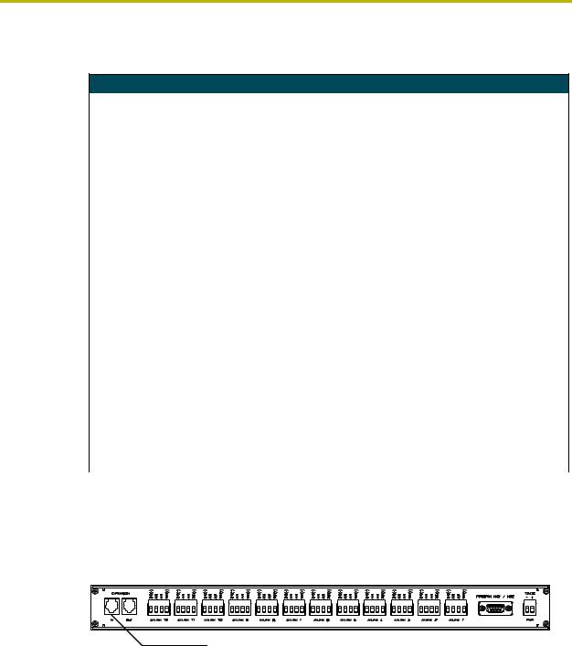
Front and rear panel components
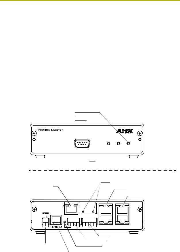
FIG. 1 shows the front and rear panel components of the NXC-ME260.
Input LED (yellow)
Output LED (red)
Status LED (green)
STATUS OUTPUT INPUT
PROGRAM
Program port (RS232)
Front |
|
|
|
|
|
|
|
Rear |
|
|
|
|
|
|
|
Ethernet 10/100 |
|
|
|
|
|
|
Ethernet 10/100 LEDs |
|
|
|
|
|
|
|
|
connector |
|
|
|
|
|
|
ICSNet connectors/LEDs |
|
|
|
|
|
|
|
|
|
|
|
|
|
|
|
ICSHub IN/OUT |
|
|
|
|
|
|
|
connectors/LEDs |
NXC-ME260 |
|
|
|
ETHERNET |
|
|
|
Master-Ethernet |
|
|
|
10/100 |
|
|
|
|
|
|
SPEED |
FD |
|
IN |
|
|
|
|
|
|
|||
|
|
|
|
|
|
|
|
12VDC |
GND |
AXM AXP |
PWR |
RTS CTS TX |
RX |
GND |
|
|
OUT |
||||||
|
|
|
|
|
|
|
|
PWR |
|
AXlink |
|
PROGRAM |
ICSNet |
ICSHub |
|
|
|
|
|
|
|
|
Program port connector (grey) |
|
|
|
|
|
|
AXLink connector |
|
12 VDC |
|
|
|
|
|
AXLink status LED (green) |
|
power connector |
|
|
|
|
|
Expansion Out connector |
|
|
|
|
|
|
|
||
FIG. 1 Front and rear panel components (NXC-ME260 card shown installed within an NXS-MHS)
NXC-ME260 NetLinx Master-Ethernet Card/Module |
1 |
|
|
|
|

Product Information
Specifications
NXC-ME260 Specifications
Dimensions (HWD): |
|
NXC Card |
1.38" x 5.43" x 9.25" (35.1 mm x 138.0 mm x 235.0 mm) |
|
|
NXS Module |
1.64" x 5.55" x 9.28" (41.7 mm x 141.0 mm x 236.0 mm) |
|
|
Weight: |
NXC-ME260 only: 0.55 lbs (0.25 kg) |
|
NXC-ME260 with NXS-NMS module: 1.95 lbs (0.88 kg) |
|
|
Power Consumption: |
750 mA @ 12 VDC |
|
|
Memory: |
Compact Flash: 32 MB standard (upgradeable) |
|
Volatile: 16 MB |
|
Non-volatile: 1 MB |
|
|
Microprocessor: |
Coldfire® 5407 (32-bit) |
Enclosure: |
Metal with black matte finish. |
|
|
Front Faceplate: |
Plastic grey with translucent viewing window. |
|
|
Front Panel Components: |
|
Program port |
DB9 (male) connector supports RS-232 communications to your PC for system |
|
programming and diagnostics. You set the port's communication speed with |
|
the Baud Rate DIP switch. See the Setting the Program Port DIP |
|
Switch section on page 5 for details. |
|
Note: There are Program ports located on the front and rear panels of the |
|
Master card for easy access. Because these ports share the same circuitry, |
|
you should never use both at the same time; doing so will result in |
|
communication and/or programming errors. |
|
|
Status LED |
Green LED lights to indicate that the system is programmed and |
|
communicating properly. |
|
|
Output LED |
Red LED lights when the Master transmits data, sets channels On and Off, |
|
sends data strings, etc. |
|
|
Input LED |
Yellow LED lights when the Master receives data from button pushes, strings, |
|
commands, channel levels, etc. |
|
|
Front Panel LEDs - |
These LEDs also display special blink patterns when a mode is activated. See |
blink patterns |
the Modes and Front Panel LED Blink Patterns section on page 7 for details. |
|
|
Program Port DIP Switch |
8-position DIP switch located behind the front panel for setting the baud rate for |
|
the Program port. |
|
• Available baud rate settings are 9600, 38,400 (default), 57,600 and 115,200 |
|
(bps). Refer to the Setting the Program Port DIP Switch section on page 5 for |
|
details. |
|
|
Rear Panel Components: |
|
PWR connector |
2-pin (male) green captive-wire connector for 12 VDC power supply. |
|
|
EXPANSION OUT port |
RJ11 connector connects to an AXB-SPE Server Port Expander. |
|
|
Ethernet 10/100 port |
RJ-45 Ethernet 10/100 connector. The Ethernet port automatically negotiates |
|
the connection speed (10 Mbps or 100 Mbps) and whether to use half duplex |
|
or full duplex mode. |
|
|
Ethernet 10/100 LEDs |
LEDs that show communication activity, connections, speeds, and mode |
|
information: |
|
• A-activity - Yellow LED blinks when receiving Ethernet data packets. |
|
• L-link - Green LED lights when the Ethernet cables are connected and |
|
terminated correctly. |
|
• SPEED - Green LED lights when transmitting data at 100 Mbps, and is Off |
|
when transmitting at 10 Mbps. |
|
• FD-full duplex - Green LED lights when running in full duplex mode, and is Off |
|
when running half duplex mode. |
|
|
|
2 |
NXC-ME260 NetLinx Master-Ethernet Card/Module |
|
|
|
Product Information
NXC-ME260 Specifications (Cont.)
Rear Panel Components |
|
(Cont:) |
|
AXlink connector |
4-pin (male) black captive-wire connector provides data and power to external |
|
control devices. |
|
• Power rating = 6 A max; actual load depends on connected power supply. |
|
|
Axlink Status LED |
Green LED lights to show AXlink and expansion port data activity. |
|
|
Program port |
5-pin (male) grey connector for system programming and diagnostics. There is |
|
a Program port located on the front and rear of the Master Cards for easy |
|
access. Because these ports share the same circuitry, you should never use |
|
both ports at the same time. Doing so will result in communication and/or |
|
programming errors. |
|
|
ICSNet connectors |
Two RJ-45 connectors that provide power (500 mA) and data to external |
|
ICSNet devices. |
|
|
ICSNet LEDs |
Green LEDs that light when receiving data on that port. |
|
|
ICSHub In/Out connectors |
Two RJ-45 connectors that provide data to other Hubs connected to the |
|
Master. |
|
|
ICSHub IN/OUT LEDs |
Yellow LEDs that light when receiving data on that port. |
|
|
Included Accessories: |
• Connector Bag containing: |
|
- One Green 2-pin 3.5 mm mini-Phoenix connector (female) (41-5025) |
|
- One Black 4-pin 3.5 mm mini-Phoenix connector (female) (41-5047) |
|
- One Grey 5-pin 3.5 mm mini-Phoenix connector (female) (41-5053) |
|
- One back panel (51-2010-61) |
|
|
Optional Accessories: |
• AC-RK Accessory Rack Kit (FG515) |
|
• PSN2.8: Power Supply (FG423-17) with 3.5 mm mini-Phoenix connector |
|
• PSN4.4: Power Supply (FG423-45) with 3.5 mm mini-Phoenix connector |
|
• PSN6.5: Power Supply (FG423-41) with 3.5 mm mini-Phoenix connector |
|
|
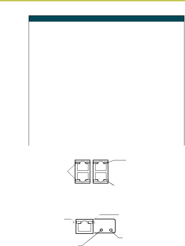
Rear panel LEDs: ICSNet/ICSHub
ICSNet LED (green) |
IN |
|||
lights to indicate data |
|
|
|
|
|
|
|
||
input activity on this port |
OUT |
|||
|
|
ICSNet |
ICSHub |
|
|
||||
FIG. 2 Layouts of the ICSNet and ICSHub LEDs
ICSHub IN LED (yellow) lights to indicate data input activity on this port
ICSHub OUT LED (yellow) lights to indicate data input activity on this port
Rear panel LEDs: Ethernet
A - Activity LED (yellow) lights when receiving Ethernet data packets
SPEED LED (green) lights when transmitting data at 100 Mbps, and is Off when transmitting at 10 Mbps
FIG. 3 Layout of Ethernet LEDs
ETHERNET 10/100
SPEED FD
L - Link LED (green) lights when the Ethernet cables are connected and terminated correctly
FD - Full Duplex LED (green) lights when running in full duplex mode, and is Off when running in half duplex mode
NXC-ME260 NetLinx Master-Ethernet Card/Module |
3 |
|
|
|
|

Product Information
|
4 |
NXC-ME260 NetLinx Master-Ethernet Card/Module |
|
|
|
Installation and Wiring
Installation and Wiring
This section contains information about configuring the Program port, cable configurations,
connector pinouts, and NXC-ME260 installation procedures.
Setting the Program Port DIP Switch
Prior to installing the NXC-ME260, configure the Program port’s communication speed by setting the baud rate DIP switch (SW1) to the appropriate setting. The Program port’s DIP switch is located to one side of the Master’s RS232 Program port.
Baud rate settings
The Program port DIP switch is located on the Master card’s circuit board. Use this DIP switch to set the baud rate used by the Program port for communication. Before programming the Master, make sure the baud rate you set matches the communication set on either your PC’s COM port or through your NetLinx Studio 2.1. By default, the baud rate is set to 38,400 (bps).
Baud Rate Settings
Baud Rate |
Position 5 |
Position 6 |
Position 7 |
Position 8 |
|
|
|
|
|
9600 bps |
OFF |
ON |
OFF |
ON |
|
|
|
|
|
38,400 bps (default) |
OFF |
ON |
ON |
ON |
|
|
|
|
|
57,600 bps |
ON |
OFF |
OFF |
OFF |
|
|
|
|
|
115,200 bps |
ON |
ON |
ON |
ON |
|
|
|
|
|
Note the orientation of the DIP Switch and the ON position label.
DIP Switch positions 2,3, and 4 must remain in the OFF position at all times.
Program Run Disable (PRD) mode
You can also use the Program Port DIP switch to set the Master card to Program Run Disable (PRD) mode according to the settings listed in the table below.
PRD Mode Settings
PRD Mode |
Position 1 |
|
|
Normal mode (default) |
OFF |
|
|
PRD Mode |
ON |
|
|
NXC-ME260 NetLinx Master-Ethernet Card/Module |
5 |
|
|
|
|
Installation and Wiring
PRD mode prevents the NetLinx program stored in the Master from running when you power up the NXC-ME260. PRD mode should only be used when you suspect the resident NetLinx program is causing inadvertent communication and/or control problems. If necessary, place the Master in PRD mode and use the NetLinx Studio 2.1 program to resolve the communication and/or control problems with the resident NetLinx program. Then, download the new NetLinx program and try again.
Think of the PRD Mode (On) equating to a PC’s SAFE Mode setting. This mode allows a user to continue powering a unit, update the firmware, and download a new program while circumventing any problems with a currently downloaded program. Power must be cycled to the unit after activating/deactivating this mode on the rear Program Port DIP switch #1.
Setting the Program Port DIP switch
It is recommended that the baud rate DIP switch be set prior to any installation of the NXC-ME260 card.
1.Locate the red baud rate DIP switch (FIG. 4).
2.Set DIP switch positions according to the information listed in the Baud Rate Settings and
PRD Mode Settings tables above.
3.Follow the procedures outlined in the NXC-ME260 Installation and Mounting Procedures section on page 15.
If the card has already been installed:
1.Disconnect the power supply from the 2-pin PWR (green) connector on the Master Card.
2.Unsecure the NXC-ME260 by unscrewing the two faceplate securing screws (on both sides of the faceplate) using a Phillips-head screwdriver (FIG. 4).
3.Carefully slide-out the card and locate the red baud rate DIP switch (FIG. 4).
4.Set the DIP switch positions according to the information listed in the Baud Rate Settings and
PRD Mode Settings tables (page 5).
5.Place the Master card back into its’ housing and resecure the two faceplate securing screws.
6.Reconnect the 12 VDC power supply to the 2-pin PWR connector and apply power.
Faceplate |
|
securing |
Baud rate DIP |
screws (2) |
switch for the |
|
Program port |
|
(red) |
Faceplate |
|
FIG. 4 Component locations on the NXC-ME260
|
6 |
NXC-ME260 NetLinx Master-Ethernet Card/Module |
|
|
|
Installation and Wiring
Modes and Front Panel LED Blink Patterns
The following table lists the modes for the ME260 and blink patterns displayed on the front panel LEDs for each mode. These patterns are not evident until after the unit is powered.
Modes and LED Blink Patterns
|
|
LEDs and Blink Patterns |
||
|
|
|
|
|
|
|
STATUS |
OUTPUT |
INPUT |
Mode |
Description |
(green) |
(red) |
(yellow) |
|
|
|
|
|
OS Start |
Starting the operating system (OS). |
On |
On |
On |
|
|
|
|
|
Boot |
Master is booting. |
On |
Off |
On |
|
|
|
|
|
Contacting DHCP |
Master is contacting a DHCP server for IP |
On |
Off |
Fast Blink |
server |
configuration information. |
|
|
|
|
|
|
|
|
Unknown DHCP |
Master could not find the DHCP server. |
Fast Blink |
Off |
Off |
server |
|
|
|
|
|
|
|
|
|
Downloading Boot |
Downloading Boot firmware to the Master |
Fast Blink |
Fast Blink |
Fast Blink |
firmware |
Card's on-board flash memory. |
|
|
|
|
Do not cycle power during this process! |
|
|
|
|
|
|
|
|
No program running |
There is no program loaded, or the |
On |
Normal |
Normal |
|
program is disabled. |
|
|
|
|
|
|
|
|
Normal |
Master is functioning normally. |
1 blink per second |
Indicates |
Indicates |
|
|
|
activity |
activity |
|
|
|
|
|
Wiring Guidelines
The Master card requires 12 VDC power from either a PSN2.8, PSN4.4, or a PSN6.5 NetLinx Power Supply to operate properly. The NXC-ME260 connects to the power supply via a 2-pin 3.5 mm mini-Phoenix connector located on the faceplate.
This unit should only have one source of incoming power. Using more than one source of power to the Master card can result in damage to the internal components and a possible burn out.
Apply power to the card only after installation is complete.
Preparing captive wires
You will need a wire stripper and flat-blade screwdriver to prepare and connect the captive wires.
Never pre-tin wires for compression-type connections.
1.Strip 0.25 inch (6.35 mm) of insulation off all wires.
2.Insert each wire into the appropriate opening on the connector (according to the wiring diagrams and connector types described in this section).
3.Tighten the screws to secure the wire in the connector. Do not tighten the screws excessively; doing so may strip the threads and damage the connector.
NXC-ME260 NetLinx Master-Ethernet Card/Module |
7 |
|
|
|
|
Installation and Wiring
Wiring length guidelines
The Master requires a 12 VDC power from a PSN to operate properly. The unit should only have one source of incoming power.
Using more than one source of power to the Master can result in damage to the internal components and a possible burn out.
An auxiliary 12 VDC power supply can provide power to the Master. Refer to the following table for wiring length information:
Wiring Length Guidelines @ 750 mA
Wire Size |
Maximum wiring length |
|
|
18 AWG |
156.49 feet (46.69 meters) |
|
|
20 AWG |
99.01 feet (30.18 meters) |
|
|
22 AWG |
61.73 feet (18.81 meters) |
|
|
24 AWG |
38.91 feet (11.86 meters) |
|
|
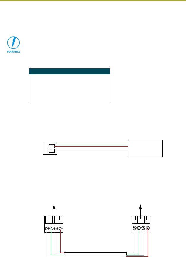
Wiring a 2-pin power connection
To use the NetLinx 2-pin 3.5 mm mini-Phoenix power supply jack for power transfer from the PSN power supply to the rear of the NXC-ME260, the incoming PWR and GND cables from the PSN must be connected to its corresponding location on the 2-pin 3.5 mm mini-Phoenix connector (FIG. 5).
PWR +
NetLinx Power Supply
GND -
To the ME260
FIG. 5 2-pin mini-Phoenix connector wiring diagram (direct power)
Using the 4-pin mini-Phoenix connector for data and power
Connect the 4-pin 3.5 mm mini-Phoenix (female) captive-wire connector to an external Netlinx device, as shown in FIG. 6.
To the ME260 |
To the external NetLinx device |
|
AXlinx/PWR connector |
||
|
Top view |
|
|
|
GND - |
AXP/TX |
AXM/RX |
PWR + |
|
|
|
Top view |
GND - |
AXP/TX |
AXM/RX |
PWR + |
FIG. 6 4-pin mini-Phoenix connector wiring diagram (direct data and power)
|
8 |
NXC-ME260 NetLinx Master-Ethernet Card/Module |
|
|
|
Installation and Wiring
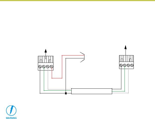
Using the 4-pin mini-Phoenix connector for data with external power
To use the NetLinx 4-pin 3.5 mm mini-Phoenix (female) captive-wire connector for data communication and power transfer; the incoming PWR and GND cable from the PSN must be connected to the AXlink cable connector going to the NXC-ME260. FIG. 7 shows the wiring diagram. Always use a local power supply to power the Master card.
To the ME260 |
To the external NetLinx device |
AXlinx/PWR connector |
|
|
|
PWR (+) |
|
|
GND (-) |
Top view |
|
|
GND - |
AXP/TX |
AXM/RX |
Local +12 VDC power supply (coming from the PSN power supply)
|
|
Top view |
GND - |
AXP/TX |
AXM/RX |
FIG. 7 4-pin mini-Phoenix connector wiring diagram (using external power source)
When connecting an external power supply, do not connect the wire from the PWR terminal (coming from the external device) to the PWR terminal on the Phoenix connector attached to the NXC-ME260. Make sure to connect only the AXM, AXP, and GND wires to the Master’s Phoenix connector when using an external PSN power supply.
Make sure to connect only the GND wire on the AXlink/PWR connector when using a separate 12 VDC power supply. Do not connect the PWR wire to the AXlink connector’s PWR (+) opening.
Program Port Connections and Wiring
The NXC-ME260 is equipped with two Program ports. One is located on the front panel and the other is on the rear for easy access. The port on the front panel is an RS232 (male) connector and the rear port is a grey 5-pin (male) connector.
Use a Programming cable to connect the Program port to your PC's COM port to communicate with the Master card. Then, you can download NetLinx programs to the Master card using the NetLinx Studio 2.1 software program. Refer to the NetLinx Studio instruction manual for programming instructions.
NXC-ME260 NetLinx Master-Ethernet Card/Module |
9 |
|
|
|
|
Installation and Wiring
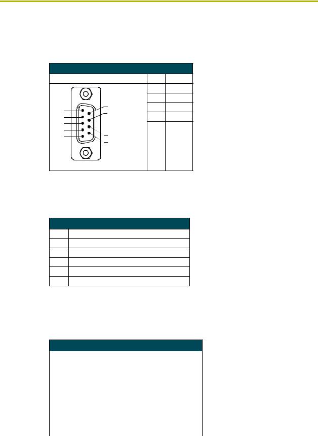
RS232 Program port (front panel)
The following table shows the front panel RS232 (DB9) Program Port connector (male), pinouts, and signals.
RS232 Program Port, Pinouts, and Signals
Program Port Connector |
Pin |
Signal |
||
|
|
2 |
RX |
|
|
|
3 |
TX |
|
5 |
9 |
5 |
GND |
|
8 |
7 |
RTS |
||
4 |
||||
|
||||
3 |
|
8 |
CTS |
|
2 |
7 |
|
|
|
1 |
|
|
||
|
6 |
|
|
|
Male
5-Pin Program port (rear panel)
The table below lists the pinouts and signals for the grey rear panel 5-pin 3.5 mm mini-Phoenix Program port connector.
5-Pin Program Port Pinouts and Signals
Pin Signal
1GND
2RX
3TX
4CTS
5RTS
ICSNet RJ-45 Connections/Wiring
The following table shows the pinouts, signals, and pairing information to use for ICSNet RJ-45 connections. The ICSNet connections provide power and data to ICSNet devices. Each port provides up to 500 mA of current.
ICSNet RJ-45 Signals
Pin |
Signal-Master |
Signal-Device |
|
|
|
1 |
TX + |
RX + |
|
|
|
2 |
TX - |
RX - |
|
|
|
3 |
N/A |
N/A |
|
|
|
4 |
GND |
GND |
|
|
|
5 |
N/A |
N/A |
|
|
|
6 |
N/A |
N/A |
|
|
|
7 |
RX + |
TX + |
|
|
|
8 |
RX - |
TX - |
|
|
|
|
10 |
NXC-ME260 NetLinx Master-Ethernet Card/Module |
|
|
|
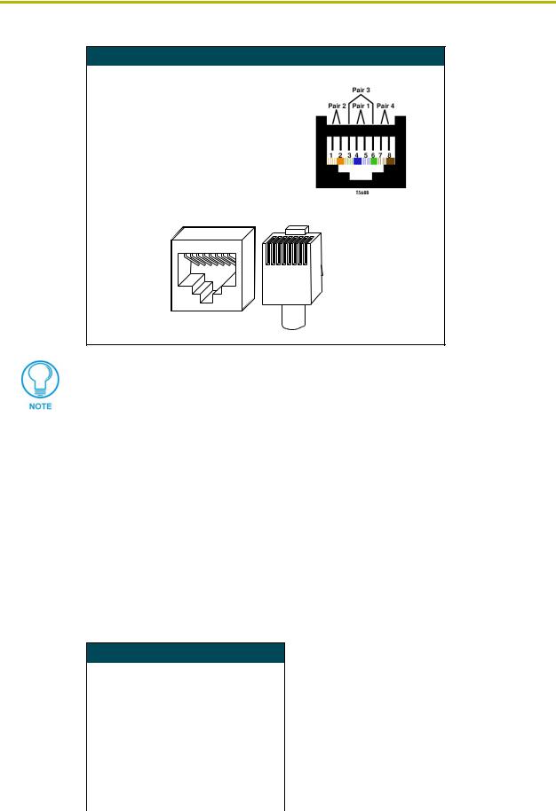
Installation and Wiring
RJ-45 Pinout Information (EIA/TIA 568 B)
Pin |
Wire Color |
Polarity |
Function |
|
|
|
||
|
|
|
|
|
|
|
|
|
1 |
Orange/White |
+ |
Transmit |
|
|
|
||
|
|
|
|
|
|
|
|
|
2 |
Orange |
- |
Transmit |
|
|
|
||
|
|
|
|
|
|
|
|
|
3 |
Green/White |
- |
Mic |
|
|
|
||
|
|
|
|
|
|
|
|
|
4 |
Blue |
- |
Ground |
|
|
|
||
|
|
|
|
|
|
|
|
|
5 |
White/Blue |
+ |
12 VDC |
|
|
|
||
|
|
|
|
|
|
|
|
|
6 |
Green |
+ |
Mic |
|
|
|
||
|
|
|
|
|
|
|
|
|
7 |
White/Brown |
+ |
Receive |
|
|
|
||
|
T IA 5 6 8 B |
|
||||||
|
|
|
|
|
|
|
||
8 |
Brown |
- |
Receive |
|||||
|
|
|
||||||
|
|
|
||||||
|
|
|
|
|
|
|
|
|
|
|
|
|
|
|
|
|
|
|
|
|
|
|
|
|
|
|
1 |
2 |
3 |
4 |
5 |
6 |
7 |
8 |
|
|
|
|
|
|
|
|
|
|
|
|
|
|
1 |
2 |
3 |
4 |
5 |
6 |
7 |
8 |
(female) |
|
|
|
|
|
|
|
|
|
|
|
|
|
(male) |
RJ-45 connector - pin configurations |
||||||||||||||
Unlike the ICSNet ports, the ICSHub connections require a specific polarity. The IN/OUT configuration, on the Hub ports, was implemented to use the same cables as ICSNet, but these ports need TX and RX crossed. You must connect an OUT to an IN, or an IN to an OUT port.
This is done simply to keep the polarity straight. The Hub bus is still a bus. All Hub connections are bi-directional.
ICSHub RJ-45 Connections/Wiring
The two ICSHub RJ-45 connectors on the rear of the Master card provide data to other Hubs connected to a downstream system. Hubs allow you to connect multiple NetLinx Hubs together in a daisy-chain configuration. Connect the OUT port to the IN port on the second or downstream NetLinx Hub.
Use CAT5 cables for all ICSHub connections.
Do not connect the last hub in a daisy-chain configuration into the first Hub.
ICSHub IN port
The following table describes the pinout and signal information for the ICSHub IN port.
ICSHub IN Pinouts and Signals
Pin |
Signal |
Color |
|
|
|
1 |
TX - |
orange-white |
|
|
|
2 |
TX + |
orange |
|
|
|
3 |
------ |
------ |
|
|
|
4 |
------ |
------ |
|
|
|
5 |
------ |
------ |
|
|
|
6 |
------ |
------ |
|
|
|
7 |
RX - |
brown-white |
|
|
|
8 |
RX + |
brown |
|
|
|
NXC-ME260 NetLinx Master-Ethernet Card/Module |
11 |
|
|
|
|
Installation and Wiring
ICSHub OUT port
The following table describes the pinout and signal information for the ICSHub OUT port.
ICSHub OUT Pinouts and Signals
Pin |
Signal |
Color |
|
|
|
1 |
RX + |
orange-white |
|
|
|
2 |
RX - |
orange |
|
|
|
3 |
------ |
------ |
|
|
|
4 |
------ |
------ |
|
|
|
5 |
------ |
------ |
|
|
|
6 |
------ |
------ |
|
|
|
7 |
TX + |
brown-white |
|
|
|
8 |
TX - |
brown |
|
|
|
Ethernet 10/100 Base-T RJ-45 Connections/Wiring
The following table lists the pinouts and signals associated to the Ethernet connector. FIG. 8 describes the RJ-45 pinouts, signals, and pairing for the Ethernet 10/100 Base-T RJ-45 connector and cable.
Ethernet RJ-45 Pinouts and Signals
Pin |
Signals |
Connections |
Pairing |
|
Color |
|
|
|
|
|
|
|
|
1 |
TX + |
1 --------- |
1 |
1 --------- |
2 |
orange-white |
|
|
|
|
|
|
|
2 |
TX - |
2 --------- |
2 |
|
|
orange |
|
|
|
|
|
|
|
3 |
RX + |
3 --------- |
3 |
3 --------- |
6 |
green-white |
|
|
|
|
|
|
|
4 |
no connection |
4 --------- |
4 |
|
|
blue |
|
|
|
|
|
|
|
5 |
no connection |
5 --------- |
5 |
4 --------- |
5 |
blue-white |
|
|
|
|
|
|
|
6 |
RX - |
6 --------- |
6 |
|
|
green |
|
|
|
|
|
|
|
7 |
no connection |
7 --------- |
7 |
7 --------- |
8 |
brown-white |
|
|
|
|
|
|
|
8 |
no connection |
8 --------- |
8 |
|
|
brown |
|
|
|
|
|
|
|
FIG. 8 diagrams the RJ-45 cable and connectors.
|
8 |
|
|
8 |
|
||
|
7 |
|
|
7 |
|
||
|
6 |
|
|
6 |
|
||
RJ-45 |
5 |
|
|
|
5 |
RJ-45 |
|
|
|
||||||
Plug |
4 |
|
|
|
4 |
Plug |
|
|
|
|
|
|
|||
|
3 |
|
|
|
3 |
|
|
|
|
|
|
|
|||
|
2 |
|
|
|
2 |
|
|
|
|
|
|
||||
FIG. 8 |
1 |
|
|
|
1 |
|
|
|
|
|
|||||
RJ-45 wiring diagram |
|
|
|
|
|||
|
12 |
NXC-ME260 NetLinx Master-Ethernet Card/Module |
|
|
|
Installation and Wiring
Ethernet ports used by the ME260
Ethernet Ports Used by the ME260
Port type |
Description |
Standard Port # |
|
|
|
ICSP |
Peer-to-peer protocol used for both Master-to-Master and Master-to-device |
1319 (UDP/TCP) |
|
communications. |
|
|
For maximum flexibility, the Master can be configured to utilize a different |
|
|
port than 1319, or disable ICSP over Ethernet completely from either |
|
|
Telnet or the Program Port located on the rear of the Master itself. |
|
|
|
|
ICMP |
When using version 1.XX of NetLinx Studio, you must be able to PING a |
ICMP |
|
Master in order to be able to connect to it over a network. |
|
|
• Note: NetLinx Studio version 2.0 or higher allows a user the ability to |
|
|
turn Off this requirement by de-selecting the "Automatically Ping the |
|
|
Master Controller to ensure availability" feature from within the |
|
|
TCP/IP Setting dialog (default condition is On). |
|
|
|
|
Telnet |
The NetLinx telnet server provides a mechanism to configure and |
23 (TCP) |
|
diagnose a NetLinx system. |
|
|
For maximum flexibility, the Master can be configured to utilize a different |
|
|
port than 23, or disable Telnet completely from either Telnet or the Program |
|
|
Port located on the rear of the Master itself. Once disabled, the only way to |
|
|
enable Telnet again is from the Master’s Program port. |
|
|
|
|
HTTP |
The Master has a built-in web server that complies with the HTTP 1.0 |
80 (TCP) |
|
specification and supports all of the required features of HTTP v1.1. |
|
|
|
|
FTP |
The NXC-ME260 has a built-in FTP server that conforms to RFC959. |
21/20 (TCP) |
|
|
|
Internet Inside |
The Internet Inside feature the Master uses, by default, is port 10500 for |
10500 (TCP) |
|
the XML based communication protocol. This port is connected to by the |
|
|
client web browser’s JVM when Internet Inside control pages are retrieved |
|
|
from the on-board Master’s web server. |
|
|
For maximum flexibility, the on-board Master can be configured to utilize a |
|
|
different port than 10500 or to disable Internet Inside completely. |
|
|
|
|
SPE Port Connection/Wiring
Use an RJ-11 cable to connect the NXC-ME260 to an AXB-SPE Slave Port Expander.
The EXPANSION OUT port on the rear panel of the NXC-ME260 connects to the EXPANSION IN port on the rear panel of the AXB-SPE (FIG. 9).
EXPANSION IN port (RJ-11)
FIG. 9 AXB-SPE (rear panel)
You can daisy chain multiple AXB-SPE's by connecting the EXPANSION OUT on the primary AXB-SPE to the EXPANSION IN port on the secondary, as shown in FIG. 10. The connecting RJ-11 cable should not exceed 6" in length. Repeat this process to connect up to nine AXB-SPE's.
NXC-ME260 NetLinx Master-Ethernet Card/Module |
13 |
|
|
|
|

Installation and Wiring
EXPANSION OUT connector on rear of NXC-ME260
NXC-ME260
Master-Ethernet
12VDC
PWR
ETHERNET 10/100
|
|
|
SPEED |
|
FD |
|
|
GND |
AXM AXP |
PWR |
RTS |
CTS TX |
RX |
GND |
|
|
AXlink |
|
PROGRAM |
ICSNet |
ICSHub |
||
EXPANSION
IN
OUT
1st AXB-SPE (rear panel)
IN OUT
RJ-11 cable (6" max)
EXPANSION
2nd AXB-SPE (rear panel)
OUT
FIG. 10 Daisy chaining two or more AXB-SPE's off of an NXC-ME260
SPE cable pinout information
The following table gives pinout information for the RJ-11 SPE connector. AMX supplies a 6" RJ-11 cable with the AXB-SPE. The EXPANSION connectors (on the AXB-SPE) use
pins 2, 3, 4 and 5. Pin 2 is Ground; the others are all pin-to-pin connections.
SPE Connector Pinouts and Signals
Pin Signal
1no connect
2GND
3TX
4TX enable
5RX
6no connect
Do not use a standard phone extension cable; it will not work with the AXB-SPE.
FIG. 11 diagrams the RJ-11 cable and connectors.
|
6 |
|
|
6 |
|
|
|
|
|
||||
RJ-11 |
5 |
|
|
5 |
RJ-11 |
|
|
||||||
4 |
|
|
4 |
|||
|
||||||
Plug |
3 |
|
|
|
3 |
Plug |
|
|
|
||||
|
2 |
|
|
2 |
|
|
|
|
|
||||
|
1 |
|
|
1 |
|
|
|
|
|
||||
FIG. 11 RJ-11 wiring diagram
|
14 |
NXC-ME260 NetLinx Master-Ethernet Card/Module |
|
|
|
Installation and Wiring
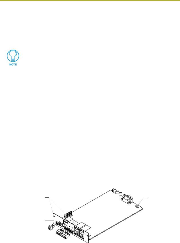
NXC-ME260 Installation and Mounting Procedures
Mounting the ME260 into an NXS-NMS
1.Confirm the contents of the shipment box to verify that you have all specified parts. Refer to the NXC-ME260 Specifications section on page 2 for more information about included and optional accessories.
2.Carefully remove the NXS-NMS Master/Hub Module from the shipping box.
3.Pull-away the magnetic faceplate from the front of the NXS-NMS. This exposes the front panel LEDs and Program port opening (FIG. 12).
4.Carefully remove the NXC-ME260 from its anti-static bag and place it aside.
5.Grasp the NXC-ME260 by the faceplate and direct the Program port (on the front of the card) into the opening on the rear of the NXS-NMS (FIG. 12).
6.Slide the Master card along the lowest pair of internal guide slots within the NXS-NMS.
Program
NXC-ME260
port
faceplate
NXC-ME260 Master card
NXS-NMS
Master/Hub Module
NXS-NMS magnetic faceplate
FIG. 12 Component locations on both NXC-ME260 and NXS-NMS
7.Secure the NXC-ME260 faceplate to the NXS-NMS by using a Phillips-head screwdriver to turn the two faceplate securing screws in a clockwise direction.
8.Connect the 12 VDC power supply to the 2-pin PWR connector and apply power.
Mounting the NXS-NMS Into an Equipment Rack
To install the Master/Hub Module into an optional AC-RK equipment rack:
1.Remove the front panel from the Module to expose the mounting holes.
2.Mount the module on the AC-RK bracket.
3.Place the AC-RK bracket (with the module) in the equipment rack and secure the bracket to the rack.
4.Replace the front panel to the Module, and reattach the plastic faceplate (if necessary).
NXC-ME260 NetLinx Master-Ethernet Card/Module |
15 |
|
|
|
|
Installation and Wiring
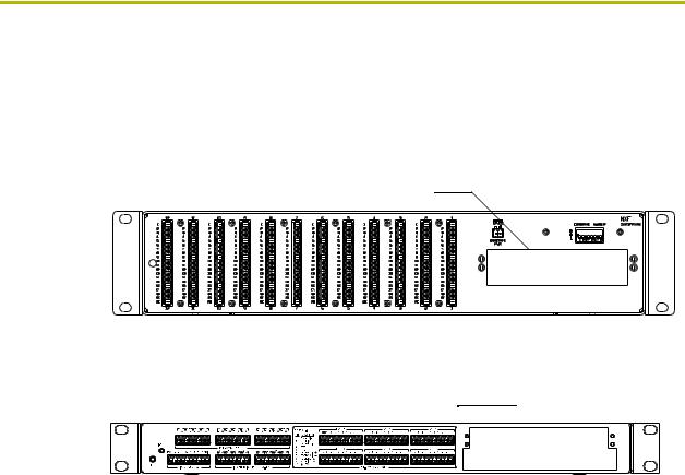
Mounting the NXC-ME260 in an NXF CardFrame or NXI
The NXC-ME260 can be installed in a NetLinx CardFrame (NXF) or NetLinx Integrated Controller (NXI). In both cases, the card mounts in a horizontal position, through the Master card slot on the rear panel of the enclosure.
FIG. 13 shows the Master Card slot on the NXF CardFrame.
Master card slot on NXF CardFrame (rear panel)
FIG. 13 Master card slot on rear panel of the NXF CardFrame
FIG. 14 shows the Master card slot on the NXI Integrated Controller.
Master Card slot on NXI (rear panel)
FIG. 14 Master card slot on rear panel of the NXI Integrated Controller
To install a Master card into either an NXF CardFrame or NXI Integrated Controller:
1.Discharge the static electricity from your body by touching a grounded object.
2.Unplug all the connectors from the Controller or Module.
3.Unscrew the two screws that hold the front faceplate plate on the Master card and remove the front plate.
4.Align the edges of the card with the guide slots inside the Master card slot on the NXF or NXI.
5.Slide the card about halfway into the slot.
6.Inside the Master card slot on the NXF or NXI, find the 6-pin control cable connector.
7.Plug the connector from the NXF or NXI into the 6-pin terminal on the Master card. This connector is keyed to ensure correct orientation.
8.Once the control cable is connected, gently slide the card all the way in until you feel the rear edge of the card lightly snap into place.
9.Re-apply power and other connections as necessary.
|
16 |
NXC-ME260 NetLinx Master-Ethernet Card/Module |
|
|
|

Installation and Wiring
Replacing the Lithium Batteries
The NXC-ME260 is equipped with two lithium batteries (FG57-0013) that have a life of approximately 2.5 years to protect their memory. When DC power is on, the batteries (FIG. 15) are not used. When replacing the batteries, remove one at a time to avoid losing the program in memory.
 Battery (CR2032 type - 20mm coin cell)
socket
FIG. 15 Lithium battery and socket
1.Discharge the static electricity from your body by touching a grounded metal object.
2.Unplug all the connectors from the Controller or Module.
NetLinx Integrated Controller (NXI): Remove the rear panel from the NXI. Then, disconnect the NXI control cable and remove the Master card.
NetLinx Module (NXS-xxx): Remove the rear panel from the Module, and remove the Master card.
3.Locate the two batteries behind the Program port on the NXC-ME260 circuit board.
4.Carefully slide one battery out of its socket and insert the new battery.
5.Plug the 2-pin PWR (green) connector to reapply power. Wait approximately 1 minute. Then, remove the PWR connector again.
6.Carefully slide the other battery out of its socket and insert the new battery.
7.Replace the Master card (re-connect the NXI control cable to the Master card if replacing in an NXI).
8.Replace and resecure the rear faceplate using the mounting screws and reconnect all communication connectors.
9.Reconnect the 12 VDC power supply to the respective PWR connector and apply power.
NXC-ME260 NetLinx Master-Ethernet Card/Module |
17 |
|
|
|
|

Installation and Wiring
|
18 |
NXC-ME260 NetLinx Master-Ethernet Card/Module |
|
|
|

Communication and Firmware Update
Communication and Firmware Update
This section outlines the steps necessary to setup a NetLinx Master for communication and then
update the on-board firmware.
Verify that the NetLinx Master firmware is build 139. Later versions of firmware can not be used on this ME260 Master.
Before beginning:
1.Setup and configure your NXC-ME260. Refer to the Installation and Wiring section on page 5 for setup procedures.
2.Verify that you have the latest NetLinx Studio installed on your PC.
3.If necessary, download the latest Studio software from www.amx.com > Tech Center > Downloadable Files > Application Files > NetLinx Studio 2.1. This program is used to setup a System number, obtain/assign the IP/URL for the connected NetLinx Master, and transfer firmware KIT files to the Master.
4.Verify that an Ethernet/ICSNet cable is connected from the rear of the unit to its’ respective connector on the Ethernet Hub (for IP/ICSNet communication).
5.Connect an RS-232 programming cable from the front of the NetLinx Master to the rear connector (COM port) on the PC being used for programming (for DB9 communication).
6.Verify that the NetLinx Master is receiving power and is turned On.
If you have previously setup communication with your Master via an IP Address, continue with the firmware update procedures outlined in the Communicating with the NetLinx Master via an IP section on page 28.
Communicating with the Master via the Program Port
1.Launch NetLinx Studio 2.1 (default location is Start >Programs > AMX Control Disc >
NetLinx Studio > NetLinx Studio 2.1).
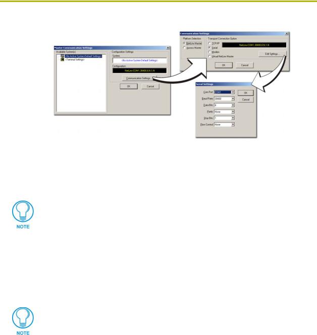
2.Select Settings > Master Communication Settings, from the Main menu, to open the Master Communication Settings dialog (FIG. 16).
3.Click the Communications Settings button to open the Communications Settings dialog (FIG. 16).
4.Click the NetLinx Master radio button (from the Platform Selection section) to indicate that you are working with a NetLinx Master (such as the NXC-ME260 or NI-Series of Integrated Controllers).
5.Click the Serial radio button (from the Transport Connection Option section) to indicate you are connecting to the Master via a (Serial) COM port.
6.Click the Edit Settings button to open the Serial Settings dialog (FIG. 16).
NXC-ME260 NetLinx Master-Ethernet Card/Module |
19 |
|
|
|
|
Communication and Firmware Update
FIG. 16 Assigning Communication Settings and Baud Rates
7.Set the COM port parameters for the selected COM port being used for communication to the NetLinx Master. Default parameters are: COM1, 38400, 8 Data Bits, No Parity, 1 Stop Bit, and No Flow Control.
8.Click OK three times to close the open dialogs and save your settings.
If the connection fails to establish:
Select a different COM port, press the Retry button to reconnect using the same communication parameters, or press the Change button to alter your communication parameters and repeat steps 2 thru 8.
Verifying the current version of NetLinx Master firmware
1.Click on the OnLine Tree tab in the Workspace window to view the devices on the System.
The default System value is one (1).
2.Right-click on the Empty Device Tree entry and select Refresh System to establish a new connection to the System’s Master and refresh the list with online system devices. The communication method is highlighted in green on the bottom of the NetLinx Studio window.
The current firmware version of the Master is displayed to the right of the device.
3.After the Communication Verification dialog window verifies active communication between the PC and the Master, verify the NetLinx Master appears in the OnLine Tree tab of the Workspace window (FIG. 17).
4.If the firmware version is not build 139 (v2_XX_139) for the NXC-ME260, follow the procedures outlined in the following sections to assign System/Device values, setup an IP Address, and then transfer the new firmware KIT file to the Master.
|
20 |
NXC-ME260 NetLinx Master-Ethernet Card/Module |
|
|
|
Communication and Firmware Update
Showing the current version of the NetLinx Studio
FIG. 17 Initial NetLinx Workspace window (showing the OnLine Tree tab)
Setting the System Value
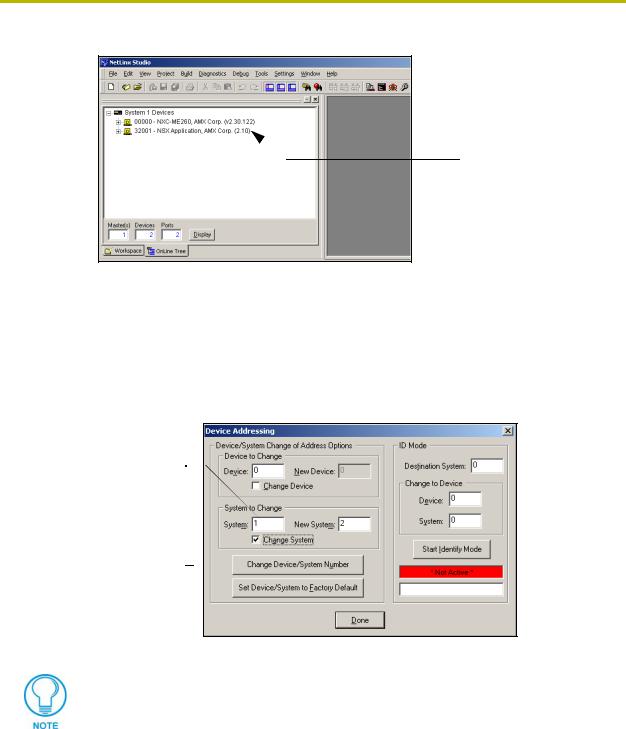
1. Access/open the Device Addressing dialog (FIG. 18) by either one of these two methods:
Right-click on any System item listed in the OnLine Tree tab of the Workspace and select Device Addressing (from the pop-up list).
Select Diagnostics > Device Addressing from the Main menu.
System Address (default for initial  system is 1)
Check-Off to verify change
FIG. 18 Device Addressing tab (changing the system value)
This tab represents the only way to change the System Number associated to the active Master.
2.Select the Change System selection box, from the System to Change section.
3.Enter both the current and new system address values (this example uses 2).
4.Click the Change Device/System Number button. This configures the Master to accept the new value and incorporate the information. The system information (in the OnLine Tree tab of the Workspace window) refreshes and then displays the new information.
5.Click Done to close the Device Addressing dialog and return to the main program.
6.Select Tools > Reboot the Master Controller to access the Reboot the Master dialog, then click Continue to reboot the Master and incorporate any changes. Allow 20 - 30 seconds for
NXC-ME260 NetLinx Master-Ethernet Card/Module |
21 |
|
|
|
|

Communication and Firmware Update
the Master to reboot. The STATUS and OUTPUT LEDs should begin to alternately blink during the incorporation. Wait until the STATUS LED is the only LED to blink.
7.Right-click the associated System number and select Refresh System to establish a new connection to the specified Master and refresh the System list with devices on that system.
8.Use Ctrl+S to save your existing NetLinx Project with the new changes.
If the NetLinx device does not appear within the OnLine Tree tab of the Workspace window of NetLinx Studio, make sure that the NetLinx Master System Number (from within the Device Addressing tab) is correctly assigned. If there is a problem, use a system value of zero (0) on the NetLinx device.
The Master is default set to DEVICE 0. Connected NetLinx device addresses can only be changed through the Protected Setup page. The new address is reflected within the OnLine Tree tab of the Workspace window only after the devices are rebooted and the system is refreshed.
Working with multiple NetLinx Masters
When using more than one Master, each unit must be assigned to a separate System value.
A Master’s System value can be changed but its’ device Address must always be set to zero (00000). The Device Addressing dialog will not allow you to alter the NetLinx Master address value.
Example: Using NetLinx Studio 2.1 to work with an NXC-ME260 and NI-4000:
The NXC-ME260 could be assigned to System 1 (with a value of 00000).
The NI-4000 could be assigned to System 2 (with a value of 00000).
Changing the system value on the Modero panel
The system value on a Modero touch panel can not be changed from the Device
Addressing dialog.
1.Press and hold the grey Front Setup Access button (below the LCD) for 3 seconds to access the Setup page.
2.Press the Protected Setup button to access the Protected Setup page.
3.Use the on-screen keyboard to enter the default password of 1988.
4.Press the System Connection button.
5.Press the blue System field on the right of the page to open the Master System Number keypad.
6.Enter the new System value (associated with the Master connected to the panel).
7.Press Back to save your changes and return to the Protected Setup page.
8.Press the on-screen Reboot button to reboot the panel.
9.Right-click the associated System number (from the OnLine Tree tab of the Workspace window) and select Refresh System to establish a new connection to the specified Master and refresh the System list with devices on that system.
10.Use Ctrl+S to save your existing NetLinx Project with the new changes.
|
22 |
NXC-ME260 NetLinx Master-Ethernet Card/Module |
|
|
|
Communication and Firmware Update
If the Master does not appear in the Workspace window, check to make sure that the Master’s System Number (from within the Device Addressing tab) is correctly assigned. If there is a problem, use a system value of zero (0) on the Master.
Changing the Device Address on a Netlinx Device
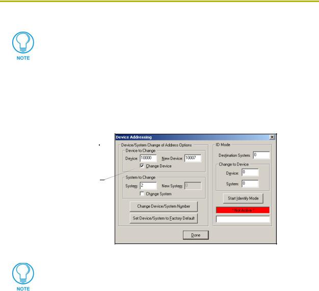
1. Access the Device Addressing dialog (FIG. 19) by either one of these two methods:
Right-click on any system device listed in the OnLine Tree tab of the Workspace and select Device Addressing (from the pop-up list).
Select Diagnostics > Device Addressing from the Main menu.
Device Address (original device  value)
Check-Off to verify change
FIG. 19 Device Addressing dialog (changing the device value)
This dialog represents the only way to change the device value of a selected NetLinx device (such as a Modero panel).
2.Select the Change Device checkbox, from the Device to Change section.
3.Enter both the Current and New Device address values for the target NetLinx device.
4.Click the Change Device/System Number button. This configures the specified Master to accept the new value for the NetLinx device and incorporate the information (the system information in the Workspace window refreshes and then displays the new information).
5.Click Done to close the Device Addressing dialog.
6.Select Tools > Reboot the Master Controller to access the Reboot the Master dialog, then click Continue to reboot the Master and incorporate any changes. Allow 20 - 30 seconds for the Master to reboot. The STATUS and OUTPUT LEDs should begin to alternately blink during the incorporation. Wait until the STATUS LED is the only LED to blink.
7.Right-click the associated System number (from the OnLine Tree tab of the Workspace window) and select Refresh System to establish a new connection to the specified Master and refresh the System list with devices on that system.
8.Use Ctrl+S to save your existing NetLinx Project with the new changes.
NXC-ME260 NetLinx Master-Ethernet Card/Module |
23 |
|
|
|
|

Communication and Firmware Update
If the Master does not appear in the Workspace window, make sure that the Master’s System Number (from within the Device Addressing tab) is correctly assigned. If there is a problem, use a system value of zero (0) on the Master.
Changing the device address on the Modero panel
The device address on a Modero touch panel can not be changed from the Device Addressing
dialog. The correct procedure to change a device address is:
1.Press and hold the grey Front Setup Access button (below the LCD on most panels) for 3 seconds to access the Setup page.
2.Press the Protected Setup button to access the Protected Setup page.
3.Use the on-screen keyboard to enter the default password of 1988.
4.Press the blue Device Number field (this opens a Device Number keypad).
5.Enter the new Device Address value.
6.Click the Done button to close the Device Addressing dialog.
7.Press the on-screen Reboot button to reboot the panel.
8.Right-click the associated System number (from the OnLine Tree tab of the Workspace window) and select Refresh System to establish a new connection to the specified Master and refresh the System list with devices on that system.
Recommended NetLinx Device numbers
• 1 - 255 |
• Axcess Devices use Axcess standards |
• 301 - 3072 |
• NetLinx CardFrames start at frame number 25 - (frame# * 12) + Card # |
• 5001 - 5999 |
• ICSNet NetLinx devices: NXI, NXM-COM2, NXM-IRS4, etc. |
• 6001 - 6999 |
• ICSNet Landmark devices: PLH-VS8, PLH-AS16, PLB-AS16 |
• 7001 - 7999 |
• InConcert Devices |
• 8001 - 8999 |
• PCLink Device: PCLink devices are PC programs |
•10000 - 31999 • ICSNet Panels: DMS, IMS, and future panels
•33001 - 36863 • Virtual devices: these start at 33001
•32001 - 32767 • Dynamic devices: the actual range used by Master
•32768 - 36863 • Virtual devices: the actual range used by Master
|
24 |
NXC-ME260 NetLinx Master-Ethernet Card/Module |
|
|
|
Loading...