


 Loading...
Operation/Reference Guide
Modero® NXD-500i
G4 Touch Panel
5" Wall/Flush Mount Touch Panel with Intercom
Touch Panels
Initial Release: 11/3/2008
AMX Limited Warranty and Disclaimer
AMX warrants its products to be free of defects in material and workmanship under normal use for three (3) years from the date of purchase from AMX, with the following exceptions:
•Electroluminescent and LCD Control Panels are warranted for three (3) years, except for the display and touch overlay components that are warranted for a period of one (1) year.
•Disk drive mechanisms, pan/tilt heads, power supplies, and MX Series products are warranted for a period of one
(1) year.
•AMX Lighting products are guaranteed to switch on and off any load that is properly connected to our lighting products, as long as the AMX Lighting products are under warranty. AMX does guarantee the control of dimmable loads that are properly connected to our lighting products. The dimming performance or quality cannot be guaranteed due to the random combinations of dimmers, lamps and ballasts or transformers.
•Unless otherwise specified, OEM and custom products are warranted for a period of one (1) year.
•AMX Software is warranted for a period of ninety (90) days.
•Batteries and incandescent lamps are not covered under the warranty.
This warranty extends only to products purchased directly from AMX or an Authorized AMX Dealer.
All products returned to AMX require a Return Material Authorization (RMA) number. The RMA number is obtained from the AMX RMA Department. The RMA number must be clearly marked on the outside of each box. The RMA is valid for a 30-day period. After the 30-day period the RMA will be cancelled. Any shipments received not consistent with the RMA, or after the RMA is cancelled, will be refused. AMX is not responsible for products returned without a valid RMA number.
AMX is not liable for any damages caused by its products or for the failure of its products to perform. This includes any lost profits, lost savings, incidental damages, or consequential damages. AMX is not liable for any claim made by a third party or by an AMX Dealer for a third party.
This limitation of liability applies whether damages are sought, or a claim is made, under this warranty or as a tort claim (including negligence and strict product liability), a contract claim, or any other claim. This limitation of liability cannot be waived or amended by any person. This limitation of liability will be effective even if AMX or an authorized representative of AMX has been advised of the possibility of any such damages. This limitation of liability, however, will not apply to claims for personal injury.
Some states do not allow a limitation of how long an implied warranty last. Some states do not allow the limitation or exclusion of incidental or consequential damages for consumer products. In such states, the limitation or exclusion of the Limited Warranty may not apply. This Limited Warranty gives the owner specific legal rights. The owner may also have other rights that vary from state to state. The owner is advised to consult applicable state laws for full determination of rights.
EXCEPT AS EXPRESSLY SET FORTH IN THIS WARRANTY, AMX MAKES NO OTHER WARRANTIES, EXPRESSED OR IMPLIED, INCLUDING ANY IMPLIED WARRANTIES OF MERCHANTABILITY OR FITNESS FOR A PARTICULAR PURPOSE. AMX EXPRESSLY DISCLAIMS ALL WARRANTIES NOT STATED IN THIS LIMITED WARRANTY. ANY IMPLIED WARRANTIES THAT MAY BE IMPOSED BY LAW ARE LIMITED TO THE TERMS OF THIS LIMITED WARRANTY.

Table of Contents |
|
Table of Contents |
|
Introduction ........................................................................................................ |
1 |
NXD-500i Specifications ........................................................................................... |
3 |
Front Bezel Button.................................................................................................... |
5 |
Ethernet and mini-USB Ports .................................................................................... |
5 |
Installation .......................................................................................................... |
7 |
Installing the Trim Ring ............................................................................................. |
7 |
Removing the Faceplate ........................................................................................... |
8 |
Installation of an NXD-500i Touch Panel................................................................... |
9 |
Pre-Wall Installation of the Rough-In Box........................................................................ |
9 |
Installing the NXD-500i panel within a Rough-In Box.................................................... |
10 |
Installing the NXD-500i into drywall ............................................................................. |
12 |
Installing the NXD-500i into a Flat Surface using #4 screws ......................................... |
15 |
Installing an NXD-500i into a Rack Mount Kit (NXA-RK5) ............................................. |
17 |
Wiring Guidelines for the NXD-500i Panel.............................................................. |
18 |
Ethernet/RJ-45 Port: Connections and Wiring ........................................................ |
18 |
NXD-500i Touch Panel Accessories .................................................................. |
19 |
PS-POE-AF PoE Injector.......................................................................................... |
19 |
Panel Calibration .............................................................................................. |
21 |
Calibrating the Modero Panel................................................................................. |
21 |
Configuring Communication ............................................................................. |
23 |
Modero Setup and System Connection .................................................................. |
23 |
Configuring and Using USB with a Virtual Master .................................................. |
25 |
Step 1: Setup the Panel and PC for USB Communication ............................................. |
25 |
Step 2: Confirm the Installation of the USB Driver on the PC ....................................... |
25 |
Step 3: Confirm and View the current AMX USB device connections ........................... |
27 |
Step 4: Use the USB to Configure a Virtual Master (using NetLinx Studio)................... |
28 |
Step 5: Confirm and View the current AMX USB device connections ........................... |
29 |
Configuring a Wired Ethernet Connection.............................................................. |
31 |
Step 1: Configure the Panel’s Wired IP Settings..................................................... |
31 |
IP Settings section - Configuring a DHCP Address over Ethernet................................. |
31 |
IP Settings section - Configuring a Static IP Address over Ethernet ............................. |
31 |
Step 2: Choose a Master Connection Mode Setting............................................... |
32 |
Step 3: Configure an Ethernet Connection Type .................................................... |
32 |
Master Connection section - Virtual Master communication over Ethernet .................. |
33 |
Master Connection section - NetLinx Master Ethernet IP Address - URL Mode............ |
35 |
Master Connection section - NetLinx Master Ethernet IP Address - Listen Mode......... |
36 |
NXD-500i 5" Wall/Flush Mount Touch Panel with Intercom |
i |
|
|

Table of Contents |
|
Master Connection section - NetLinx Master Ethernet IP Address - Auto Mode........... |
36 |
Using G4 Web Control to Interact with a G4 Panel ................................................ |
37 |
Using the NetLinx Master to control the G4 panel ................................................. |
38 |
Upgrading Modero Firmware ........................................................................... |
43 |
Upgrading the Firmware via the USB port.............................................................. |
43 |
Step 1: Configure the panel for a USB Connection Type .............................................. |
43 |
Step 2: Prepare NetLinx Studio for communication via the USB port ........................... |
44 |
Step 3: Confirm and Upgrade the firmware via the USB port ....................................... |
45 |
Setup Pages and Descriptions .......................................................................... |
47 |
Setup Navigation Buttons....................................................................................... |
47 |
Protected Setup...................................................................................................... |
47 |
Setup Page ............................................................................................................. |
48 |
Information ............................................................................................................. |
50 |
Panel Information Page ................................................................................................. |
50 |
Panel Information Page ................................................................................................. |
51 |
Time & Date Settings Page ........................................................................................... |
53 |
Audio Settings Page...................................................................................................... |
54 |
Supported sampling rates for WAV............................................................................... |
55 |
Protected Setup Navigation Buttons ...................................................................... |
56 |
Protected Setup Page............................................................................................. |
57 |
System Settings Page.................................................................................................... |
59 |
Calibration Page............................................................................................................ |
61 |
G4 Web Control Page ................................................................................................... |
62 |
Other Settings ........................................................................................................ |
64 |
Cache Settings Page...................................................................................................... |
64 |
Setting the image cache................................................................................................ |
65 |
Clearing the image cache .............................................................................................. |
66 |
Checking image cache status ........................................................................................ |
66 |
Password Settings Page ................................................................................................ |
67 |
Sensor Setup ................................................................................................................. |
68 |
Making the most of the Light bargraph ........................................................................ |
69 |
Making the most of the Motion Sensor feature ............................................................ |
69 |
Tools ....................................................................................................................... |
70 |
Panel Logs Page ............................................................................................................ |
71 |
Checking the Panel Connection Logs ............................................................................ |
71 |
Refreshing the Panel Connections Log.......................................................................... |
71 |
Clearing the Panel Connections Log.............................................................................. |
72 |
Panel Statistics Page ..................................................................................................... |
72 |
Checking the Panel Statistics......................................................................................... |
73 |
ii |
NXD-500i 5" Wall/Flush Mount Touch Panel with Intercom |
|
|

|
Table of Contents |
Refreshing the Panel Statistics ...................................................................................... |
73 |
Clearing the Panel Statistics.......................................................................................... |
73 |
Connection Utility Page ................................................................................................ |
74 |
Using the Connection Utility ......................................................................................... |
75 |
Programming .................................................................................................... |
77 |
Button Assignments ............................................................................................... |
77 |
Page Commands ..................................................................................................... |
77 |
Programming Numbers for Colors, Fonts, and Borders.......................................... |
83 |
RGB triplets and names for basic 88 colors .................................................................. |
83 |
Font styles and ID numbers........................................................................................... |
85 |
Border styles and Programming numbers ..................................................................... |
86 |
Telnet Commands................................................................................................... |
88 |
"^" Button Commands ........................................................................................... |
89 |
Text Effect Names ................................................................................................ |
108 |
Button Query Commands ..................................................................................... |
109 |
Panel Runtime Operations .................................................................................... |
118 |
Input Commands................................................................................................... |
122 |
Embedded codes.................................................................................................. |
123 |
Panel Setup Commands ........................................................................................ |
124 |
Dynamic Image Commands................................................................................... |
125 |
Intercom Commands............................................................................................. |
127 |
Panel IR Commands .............................................................................................. |
129 |
Troubleshooting ............................................................................................. |
131 |
Appendix A .................................................................................................... |
135 |
Text Formatting Codes for Bargraphs/Joysticks................................................... |
135 |
Text Area Input Masking....................................................................................... |
136 |
Input mask character types ......................................................................................... |
136 |
Input mask ranges ....................................................................................................... |
137 |
Input mask next field characters ................................................................................. |
137 |
Input mask operations................................................................................................. |
137 |
Input mask literals ....................................................................................................... |
137 |
Input mask output examples ....................................................................................... |
138 |
URL Resources ...................................................................................................... |
139 |
Special escape sequences ........................................................................................... |
139 |
NXD-500i 5" Wall/Flush Mount Touch Panel with Intercom |
iii |
|
|

Table of Contents
iv |
NXD-500i 5" Wall/Flush Mount Touch Panel with Intercom |
|
|
Introduction
Introduction
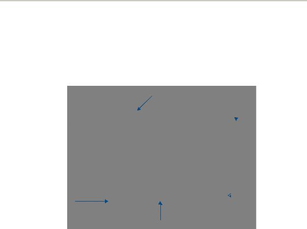
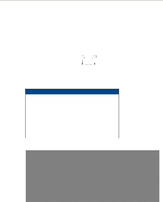
The NXD-500i 5" Modero Wall/Flush Mount Touch Panel with Intercom (FG2261-02) is a widescreen full-color mini-touch panel with full sound and intercom capability (FIG. 1). It offers the same perimeter footprint as the NXD-CV5, but with a shallower mounting depth.
Faceplate
 Microphone
Touch screen 
 Button Trim Ring
Speaker
Front Bezel button
FIG. 1 NXD-500i Color Video Touch Panel
This panel includes a built-in microphone, speakers, a mini-USB port for programming and audio output, and one NetLinx-programmable button.
NXD-500i 5" Wall/Flush Mount Touch Panel with Intercom |
1 |
|
|
Introduction
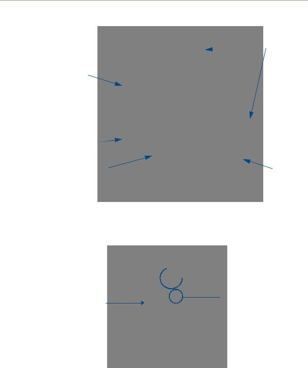
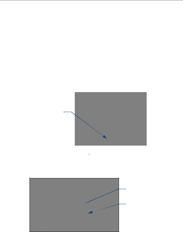
 Locking tabs
Touch screen 
Button trim ring |
|
Front Bezel button |
Back box |
|
FIG. 2 NXD-500i Color Video Touch Panel - Schematics
FIG. 3 shows the connectors located on the NXD-500i Modero panel. The mini-USB port is used both for programming the touch panel and for audio output. The mini-USB port automatically detects the presence of a headphone adaptor, allowing the port to be used for headphone connectivity.
 Ethernet 10/100 port
Mini-USB port
Back box
FIG. 3 NXD-500i Color Video Touch Panel - side view of connectors
The NXD-500i supports Intercom functionality, which allows two communicating panels (controlled by the NetLinx Master) to transmit full-duplex audio signals over a network in order for it to be used as an Intercom system.
2 |
NXD-500i 5" Wall/Flush Mount Touch Panel with Intercom |

Introduction
Key features include:
Support of AMX's 4th generation (G4) graphics which provide higher brightness, richer colors, and deeper contrast. The new G4 graphics technology is supported by the TPDesign4 Touch Panel Design application, available for download from www.amx.com.
Display of images on a large 16:9 image format, while providing a wide 90-degree top-to- bottom viewing angle.
A front panel light sensor, motion sensor, IR receiver and a Sleep/Setup Access button.
Utilization of the Voice Over Internet protocol (VoIP), which allows telephone calls to be made or received directly from the touch panel.
Support of AMX Computer Control, which enables remote viewing and control of any networked computer directly from the panel. This gives the user the ability to launch digital music from a PC, cruise the Internet, check and respond to E-mail, open software files, and launch applications. Anything you can do on your PC can be accomplished through these panels.
Programmable firmware that can be upgraded via the mini-USB port in the back of the device.
NXD-500i Specifications
The specifications for the 5" Widescreen Modero panel include:
Specifications for NXD-500i 5" Widescreen Video Touch Panel (FG2261-02)
Dimensions (HWD): |
• NXD-500i (with faceplate): 4.15" x 5.59" x 1.97" |
|
(10.50 cm x 14.20 cm x 5 cm) |
|
• CB-TP5i Rough-In/Wallbox (optional): 4.27" x 5.14" x 3.40" |
|
(10.86 cm x 13.06 cm x 8.64 cm) |
|
|
Power Requirements: |
• PoE Powered - No local Power Supply needed. |
|
• Max power draw: 5.5W. |
|
|
Memory (factory default): |
• 128 MB SDRAM |
|
• 256 MB integrated Flash Memory (not upgradeable - factory programmed) |
|
|
Weight: |
• 0.80 lbs (0.36 kg) |
|
|
Certifications: |
• FCC Part 15 Class B |
|
• CE |
|
• IEC 60950 |
|
• RoHS |
|
|
Panel LCD Parameters: |
• Aspect ratio: 16 x 9 |
|
• Maximum brightness (luminance): 200 cd/m2 |
|
• Channel transparency: 8-bit Alpha blending |
|
• Contrast ratio: 250:1 |
|
• Display colors: 256 thousand colors (18-bit color depth) |
|
• Dot/pixel pitch: 0.14 mm |
|
• Panel type: TFT Color Active-Matrix |
|
• Screen resolution: 800 x 480 pixels (HV) @ 60 Hz frame frequency |
|
• Viewing dimensions: 4.3" x 2.58" (109.2 mm x 65.2 mm) |
|
|
Active Viewing Area: |
• 4.25” x 2.55” (10.80cm x 6.48cm) |
|
|
Viewing Angles: |
• Up/Down/Left/Right: 40/80/60/60 |
|
|
IR Reception Angle: |
• Horizontal: + 25° (left and right from center) |
|
• Vertical: + 15° (up and down from center) |
|
|
Audio |
• G.711 sound standard |
|
• 75dB SPL@1m |
|
|
NXD-500i 5" Wall/Flush Mount Touch Panel with Intercom |
3 |
|
|

Introduction
Specifications for NCXC-500i 5" Widescreen Video Touch Panel (Cont.)
Supported Audio Sample |
• 48000Hz, 44100Hz, 32000Hz, 24000Hz, 22050Hz, 16000Hz, 12000Hz, |
Rates: |
11025Hz, and 8000Hz. |
|
|
Intercom: |
• Full duplex VoIP capabilities. |
|
|
Front Panel Components: |
|
Light sensor: |
• Motion-sensitive light detector for automatic adjustment of the panel |
|
brightness (a dim room results in a dimmer LCD display, and a bright room |
|
results in a brighter LCD display). |
|
Note: The light sensor can be adjusted via the Sensor Setup page (page 64). |
|
|
Motion sensor (PIR): |
• Proximity Infrared Detector to wake the panel when the panel is approached. |
|
• Activation range: + 25° (left and right from center) and + 15° (up and down |
|
from center). |
|
Note: This sensor can be adjusted via the Sensor Setup page (see page 64). |
|
|
Front Bezel button: |
• Provides both access to the Setup and Calibration page and toggles the |
|
panel between a "sleep" or "wake" state. "Sleep" status means the backlight |
|
is Off. |
|
|
Microphone: |
• Frequency response of 300 to 3400Hz |
|
• Used for intercom applications |
|
|
Speaker: |
• Output of 4Ohm |
|
• 2 Watts |
|
• 300Hz cutoff frequency |
|
|
Side Panel Components: |
|
Ethernet 10/100 port: |
• RJ-45 port for 10/100 Mbps communication. The Ethernet port automatically |
|
negotiates the connection speed (10 Mbps or 100 Mbps), and whether to use |
|
half duplex or full duplex mode. Power is supplied through Power Over |
|
Internet (PoE) |
|
• NXD-500i panels communicate with the NetLinx Master using the ICSP |
|
protocol over Ethernet. |
|
• LEDs show communication activity, connections, speeds, and mode |
|
information: |
|
L/A-link/activity - yellow LED lights On when the Ethernet cables are |
|
connected and terminated correctly and then blinks when receiving Ethernet |
|
data packets. |
|
SPD-speed - Green LED lights On when the connection speed is 100 Mbps |
|
and turns Off when the speed is 10 Mbps. |
|
|
Mini-USB connector: |
• 5-pin Mini-USB connector used for programming, firmware update, and touch |
|
panel file transfer between the PC and the target panel. The connector is |
|
also used for providing audio output for external speakers. |
|
Note: When connecting the panel to PC using a CC-USB (or compatible) |
|
cable, be sure to power the panel On before attempting to connect the USB |
|
cable from the PC to the mini-USB port on the panel. Refer to the Configuring |
|
and Using USB with a Virtual Master section on page 25 for more information. |
|
|
Button Assignments: |
Button assignments can only be adjusted in TPD4 and not on the panel. |
|
• Button channel range: 1 - 4000 button push and feedback (per address port) |
|
• Button variable text range: 1 - 4000 (per address port) |
|
• Button states range: 1 - 256 (General Button; 1 = Off State, 2 = On State) |
|
• Level range: 1 - 600 (default level value 0-255, can be set up to 1-65535) |
|
• Address port range: 1 - 100 |
|
|
Operating / Storage |
• Operating Temperature: 0° C (32° F) to 40° C (104° F) |
Environment: |
• Operating Humidity: 5% - 85% relative humidity (non-condensing) |
|
• Storage Temperature: -20° C (-4° F) to 60° C (140° F) |
|
• Storage Humidity: 5% - 85% RH |
|
|
4 |
NXD-500i 5" Wall/Flush Mount Touch Panel with Intercom |
Introduction
Specifications for NCXC-500i 5" Widescreen Video Touch Panel (Cont.)
Included Accessories: • NXD-500i Installation Guide (93-2261-02)
• Front Bezel (60-2261-11)
Other AMX Equipment: • CB-TP5i Rough-In/Wallbox (FG038-11)
•Back Cover for CB-TP5i Rough-In/Wallbox (FG038-12)
•PS-POE-AF PoE Injector (FG423-80)
•CC-USB Type-A to Mini-B 5-wire programming cable (FG10-5965)
•USB to Headphone Adaptor (FG5966-23)
•NXA-RK5 Rack Mount Kit for 5" Wall Mount panels (FG2904-55):
-5" Rackmount
-Four Screws, #10-32 x.625, PH Truss, BLK
-Four Washers, #10, Black Nylon
-Three Screws, #4-40 x.250, PPH, BLK
Front Bezel Button
The NXD-500i has only one button on the front of the device, in the center of the button trim ring. This button has several uses:
Press the button once to start a previously programmed function, or to turn off the display if not previously programmed.
Press and hold the button for 6 seconds to put the device into Setup Mode (please see the Setup Page section on page 48 for more information).
Press and hold the button for 9 seconds to enter Calibration Mode (please see the Panel Calibration section on page 21 for more information).
Press and hold the button for 20 seconds to reboot the panel.
Ethernet and mini-USB Ports
The NXD-500i has no power input port. Instead, all power is supplied via the Power over Ethernet (PoE) protocol. With PoE, the power is supplied directly through the Ethernet port through the PS-POE-AF PoE Injector, available from AMX. For more information on the PS-POE-AF POE Injector, please refer to the PS-POE-AF PoE Injector section on page 19.
The mini-USB port is used solely for software upload and audio output. The mini-USB port automatically detects the presence of a headphone adaptor, allowing the port to be used for headphone connectivity. For more information on software upgrading, please refer to the Upgrading the Firmware via the USB port section on page 43.
NXD-500i 5" Wall/Flush Mount Touch Panel with Intercom |
5 |
|
|

Introduction
6 |
NXD-500i 5" Wall/Flush Mount Touch Panel with Intercom |
Installation
Installation
While the NXD-500i is designed to fit into pre-existing NXD-CV5 touch panel sites, the actual installation differs from that of the NXD-CV5 is several significant ways. The NXD-500i can be installed either directly into the (optional) CB-TP5i Rough-In Box or another solid surface environment, using either solid surface screws or the included locking tabs for different mounting options. For more information, please refer to the NXD-500i User Manual, available at www.amx.com.
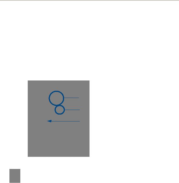
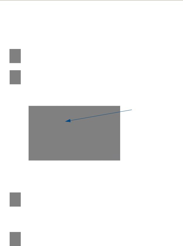
The NXD-500i is contained within a clear outer housing known as the back box (FIG. 4). This back box is removed when installing the device into a wall or into a Rough-In Box. Because of the backbox, the device may be installed into either a pre-wall surface using a CB-TP5i conduit/wallbox, or into a solid surface using the included locking tabs or either solid surface or drywall screws.
10/100 BaseT Ethernet port
Mini-USB programming port
Plastic backbox
 Front of device
FIG. 4 NXD-500i - Side view
Make sure to remove the protective plastic cover from the LCD. If the cover is not removed, the panel may not respond properly to touch points on the LCD or allow proper screen calibration.
Installing the Trim Ring
The outer Trim Ring is secured to the Faceplate with plastic latches. The Trim Ring must first be removed to install the touch panel, and is later resecured when installation is complete.
To install the Trim Ring:
1.Place the Button Trim Ring, latch side down, atop the Faceplate.
2.Firmly press down around the Button Trim Ring until all of the latches are securely inserted into their openings on the Faceplate, and the Button Trim Ring is securely fastened. Verify that the Button Trim Ring is firmly inserted onto the Faceplate and that no gaps remain between this Trim Ring and the outer surface of the Faceplate.
3.Place the Faceplate back onto the device. Make sure to align the Microphone, Light, and PIR Motion sensor locations on the main unit to their respective openings on the Faceplate assembly.
NXD-500i 5" Wall/Flush Mount Touch Panel with Intercom |
7 |
|
|

Installation
Removing the Faceplate
In certain circumstances, the Faceplate must be removed and replaced with a new faceplate. Because the device is installed against a wall, the faceplate must be removed carefully to prevent the two top prongs on the underside of the Faceplate from being broken. To remove the faceplate:
1.Gently lift up on the faceplate from the bottom. Do NOT pull up from the sides or the top.
2.Let the faceplate fall forward from the top of the device and let it pivot from the bottom.
3.Remove the faceplate from the two bottom prongs and install the new trim ring if necessary.
4.Place the Faceplate back onto the device. Make sure to align the Microphone, Light, and PIR Motion sensor locations on the device to their respective openings on the Faceplate assembly.
8 |
NXD-500i 5" Wall/Flush Mount Touch Panel with Intercom |
Installation
Installation of an NXD-500i Touch Panel
The NXD-500i can be installed either directly into the (optional) CB-TP5i Rough-In Box or other solid surface environment, using solid surface screws or the included locking tabs as mounting options. The following sections describe mounting the touch panel directly into a pre-wall rough-in box, a solid surface, drywall, or an NXA-RK5 Rack Mount Kit.
Pre-Wall Installation of the Rough-In Box
The CB-TP5i Rough-In Box (FG038-11) is an optional metallic box that is secured onto a stud/beam in a pre-wall setting, where no walls are present. Installation procedures and configurations can vary, depending on the installation environment. This section describes the installation procedures for the most common installation scenarios.
In order to guarantee a stable installation of the NXD-500i, the distance between the CB-TP5i and the outer wall surface must be a minimum of .50 inches (1.27cm) and a maximum of .875 inches (2.22cm).
Cutting out the surface slightly smaller than what is outlined in the installation drawings, to allow any necessary cutout adjustments, is highly recommended.
1.Attach the optional Back Cover for the CB-TP5i (FG038-12) if necessary.
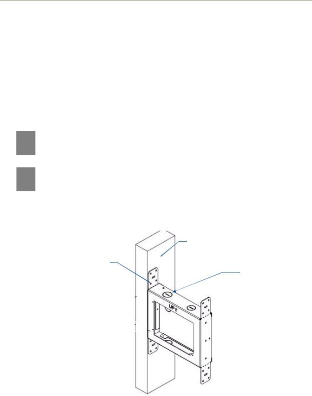
2.Fasten the CB-TP5i Rough-In Box to the stud through the holes on the Stud Mounting tabs (FIG. 5), using either nails or screws.
Stud
Stud Mounting tabs
Wiring knockouts
FIG. 5 CB-TP5i Rough-In Box components
3.Remove the appropriate wiring knockouts from the rough-in box (FIG. 5) to accommodate the cables being threaded through to the NXD-500i touch panel.
4.Thread the incoming Ethernet and USB wiring through the knockouts. Use of the left wiring knockouts are recommended with this installation. Leave enough slack in the wiring to accommodate any re-positioning of the panel.
NXD-500i 5" Wall/Flush Mount Touch Panel with Intercom |
9 |
|
|
Installation
5.Install the drywall/sheetrock before inserting the main NXD-500i device into the CB-TP5i.
Installing the NXD-500i panel within a Rough-In Box
The Rough-In Box must be mounted prior to continuing this section. Refer to the procedures in the Pre-Wall Installation of the Rough-In Box section on page 9 for detailed pre-wall installation instructions. Verify that all necessary cables have been threaded through the knockouts on the left of the Rough-In Box and the connections have been tested prior to installation of the NXD-500i.
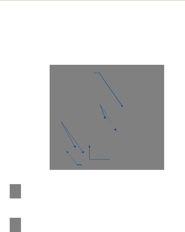
1.Remove the Faceplate bezel (A in FIG. 6) from the main NXD-500i unit (B in FIG. 6) by gripping the faceplate from the top and lifting up and then pulling with gentle outward force.
C - Optional CB-TP5i |
|
Stud |
|
||
rough-in/wallbox |
|
|
Locking Tab
Screws for mounting
Back Box to touch panel
B - Main NXD-500i unit consists of the touch panel and back box housing
A - Faceplate/Trim Ring
FIG. 6 NXD-500i panel installation into a CB-TP5i (pre-wall construction)
Be sure to pull the faceplate UP before pulling it out and away from the rest of the device. Pulling straight outward may lead to damage to the faceplate, including breaking off the tabs that attach the faceplate to the device.
2.Gently unscrew the two screws attaching the NXD-500i to its back box. These are at the bottom of the device, underneath the touch screen. Carefully remove the NXD-500i from the back box.
While the screws are loosened, you can adjust the LCD to ensure it is parallel to the sides of the backbox, if necessary. While adjusting the LCD is possible, it is not required in most cases.
3.Thread the incoming Ethernet and USB wiring from their terminal locations through the surface opening. Leave enough slack in the wiring to accommodate any re-positioning of the panel.
4.Push the back box into the wall opening. Insure that the locking tabs lie flush against the back box.
5.Extend the locking tabs on the sides of the back box by tightening the screws inside the box. Not all of the tabs must be extended to lock the back box in place, but extending a minimum of the top and bottom tabs is highly recommended. Apply enough pressure to the screw head to keep the box flush
10 |
NXD-500i 5" Wall/Flush Mount Touch Panel with Intercom |

Installation
with the wall: this ensures that the locking tabs will tighten up against the inside of the wall. The back box is clear to allow visual confirmation that the tabs have been extended and are gripping the wall. This also allows visual confirmation if the entire assembly has to be removed from the wall for any reason.
The maximum recommended torque to screw in the locking tabs on the back box is 105 IN-OZ [74 N-CM]. Applying excessive torque while tightening the locking tab screws, such as with powered screwdrivers, can strip out the tabs or damage the back box.
6.Connect both connectors to their corresponding locations along the left side of the NXD-500i touch panel.
7.Test the incoming wiring by attaching the panel connections to their terminal locations and applying power via the PoE Injector. Verify that the panel is receiving power and functioning properly to prevent repetition of the installation.Test the incoming wiring by connecting the panel connections to their terminal locations and applying power via the PoE Injector. Verify that the panel is receiving power and functioning properly to prevent repetition of the installation.
Do not disconnect the connectors from the touch panel. The unit must be installed with the attached connectors before being inserted into the Rough-In Box.
8.Install the NXD-500i into the back box.
9.The microphone cable is taped to the back box. Connect the microphone cable to its connector, making sure that the cable does not interfere with reattachment of the Faceplate.
10.Install the two Plastite screws attaching the NXD-500i to the back box (FIG. 6).
11.Place the Faceplate/Trim Ring assembly (A in FIG. 6) back onto the main NXD-500i unit (B in FIG. 6). Make sure to align the Microphone, Light, and PIR Motion sensor locations to their respective openings on the front faceplate/bezel.
12.Reconnect the terminal Ethernet and USB to their respective locations on the Ethernet port and NetLinx Master.
NXD-500i 5" Wall/Flush Mount Touch Panel with Intercom |
11 |
|
|
Installation
Installing the NXD-500i into drywall
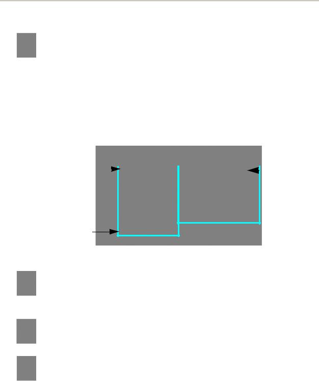
Unlike most AMX touchpanels, the NXD-500i comes with a clear plastic backbox (FIG. 7) designed to attach the panel to standard drywall. This backbox has a locking tab on three of the four faces (missing only on the face containing the space for the connections) to help lock the backbox to the wall. These locking tabs are only extended AFTER the backbox is inserted into the wall.
Locking tab screws
Locking tabs - Closed |
Locking tabs - Open |
FIG. 7 NXD-500i backbox with closed and open locking tabs
When installing the backbox, make absolutely sure that the assembly is in the correct position and in the correct place. Once the locking tabs are extended and locked into place, removing the backbox will be very difficult without having access to the back of the wall itself or damaging the wall.
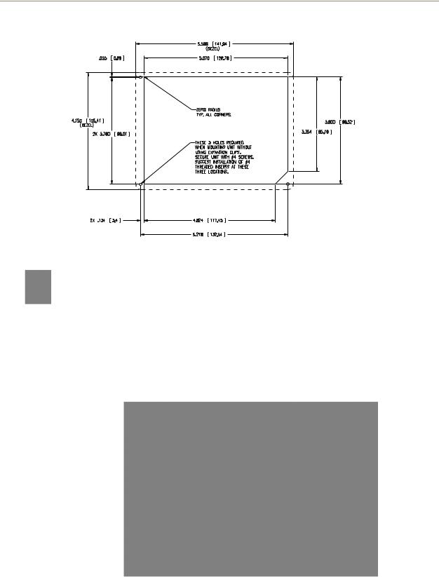
Refer to the diagram for detailed installation dimensions as shown in FIG. 8.
Cutting out the surface slightly smaller than what is outlined in the installation drawings, in order to make any necessary cutout adjustments, is highly recommended.
1.Prepare the area by removing any screws or nails from the drywall before beginning the cutout process.
2.Cut out the surface for the back box. Refer to the dimensions in FIG. 8 for more information.
12 |
NXD-500i 5" Wall/Flush Mount Touch Panel with Intercom |
Installation
FIG. 8 NXD-500i Wall Mount panel dimensions
Making sure that the actual cutout opening be slightly smaller than the provided dimensions is highly recommended. This action provides the installer with a margin for error if the opening needs to be expanded. Too little drywall removed is always better than too much.
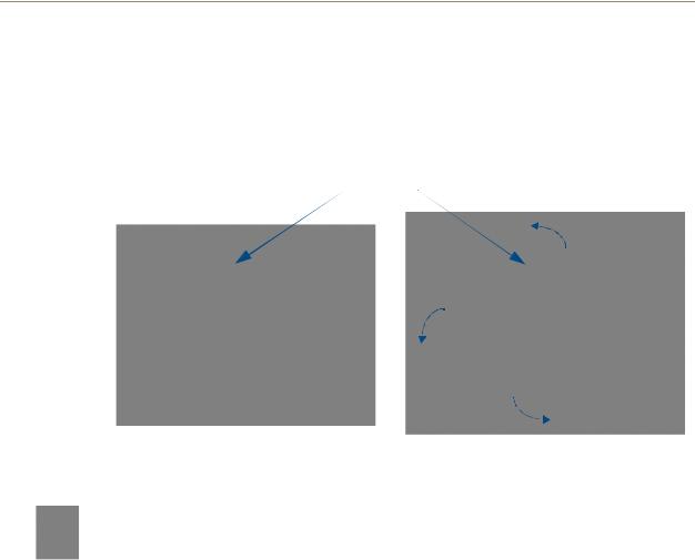
3.Remove the Faceplate/bezel (A in FIG. 9) from the main NXD-500i device (B in FIG. 9) by gripping the faceplate and pulling up and then out with gentle outward force.
4.Thread the incoming Ethernet and USB wiring from their terminal locations through the surface opening. Leave enough slack in the wiring to accommodate any re-positioning of the panel.
5.Connect both connectors to their corresponding locations along the left side of the NXD-500i touch panel.
B
A
FIG. 9 Wall Mount panel (NXD-500i) installation view for drywall surfaces - top view
6.Test the incoming wiring by attaching the panel connections to their terminal locations and applying power via the PoE Injector. Verify that the panel is receiving power and functioning properly to prevent repetition of the installation.
NXD-500i 5" Wall/Flush Mount Touch Panel with Intercom |
13 |
|
|

Installation
Do not disconnect the connectors from the touch panel. The unit must be installed with the attached connectors before being inserted into the drywall.
7.Push the back box into the wall opening. Insure that the locking tabs lie flush against the back box.
8.Extend the locking tabs on the sides of the back box by tightening the screws inside the box. Not all of the tabs must be extended to lock the back box in place, but extending a minimum of the top and bottom tabs is highly recommended. Apply enough pressure to the screw head to keep the box flush with the wall: this ensures that the locking tabs will tighten up against the inside of the wall.
The back box is clear to allow visual confirmation that the tabs have been extended and are gripping the wall. This also allows visual confirmation if the entire assembly has to be removed from the wall for any reason.
The maximum recommended torque to screw in the locking tabs on the back box is 105 IN-OZ [74 N-CM]. Applying excessive torque while tightening the locking tab screws, such as with powered screwdrivers, can strip out the tabs or damage the back box.
9.Install the NXD-500i into the back box.
10.The microphone cable is taped to the back box. Connect the microphone cable to its connector, making sure that the cable does not interfere with reattachment of the Faceplate.
11.Install the two Plastite screws attaching the NXD-500i to the back box (FIG. 6).
12.Place the Faceplate/Trim Ring assembly (A in FIG. 9) back onto the main NXD-500i unit (B in FIG. 9). Make sure to align the Microphone, Light, and PIR Motion sensor locations to their respective openings on the front faceplate/bezel.
13.Reconnect the terminal Ethernet and USB to their respective locations on the Ethernet port and NetLinx Master.
14 |
NXD-500i 5" Wall/Flush Mount Touch Panel with Intercom |

Installation
Installing the NXD-500i into a Flat Surface using #4 screws
Three #4 mounting screws (not included) are secured through circular holes located at the left and right sides of the NXD-500i. The most important thing to remember when mounting the NXD-500i is that the back box must be installed flush against the mounting surface.
Refer to SP-2261-02 for detailed installation dimensions (reproduced in FIG. 10).
Cutting out the surface slightly smaller than what is outlined in the installation drawings in order to make any necessary cutout adjustments, is highly recommended.
1.Prepare the area by removing any screws or nails from the surface before beginning the cutout process.
2.Cut out the surface for the NXD-500i Wall Mount unit using the dimensions shown in FIG. 10.
FIG. 10 NXD-500i Wall Mount panel dimensions using #4 mounting screws
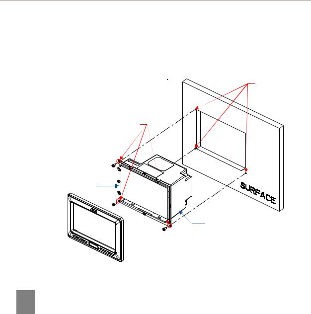
3.Remove the Faceplate/bezel (A in FIG. 11) from the main NXD-500i unit (B in FIG. 11) by gripping the faceplate and pulling up and out with gentle force.
4.Thread the incoming Ethernet and USB wiring from their terminal sources through the surface opening. Leave enough slack in the wiring to accommodate any re-positioning of the panel.
5.Connect all connectors to their corresponding locations along the left side of the un-powered NXD-500i touch panel.
NXD-500i 5" Wall/Flush Mount Touch Panel with Intercom |
15 |
|
|
Installation
The USB connectors can be from either a USB extension cable or a wireless USB RF transmitter.
6.Test the incoming wiring by connecting the panel connections to their terminal locations. Verify that the panel is receiving power and functioning properly before finalizing the installation.
Flat installation surface
Install the three #4 Mounting Screws (not included) into these three holes (suggested length of screws is 0.25")
Attachment is done along the edges
of the cutout
Locking Tab
B - Main NXD-500i unit
 A - Faceplate/Trim Ring
FIG. 11 Wall Mount panel installation configuration for flat surfaces
Do not disconnect the connectors from the touch panel. The unit must be installed with the necessary connectors before being inserted into the solid surface.
7.Carefully slide the main unit into the cutout, making sure that the locking tabs lie flush against the back box.
8.Insert and secure three #4 Mounting Screws (not included) into the corresponding holes located along the sides of the NXD-500i, using a grounded Phillips-head screwdriver, until the unit is secure and flush against the wall (FIG. 11).
9.Place the Faceplate/Trim Ring assembly (A in FIG. 11) back onto the device (B in FIG. 11). Make sure to align the Microphone, Light, and PIR Motion sensor locations to their respective openings on the front bezel/faceplate.
16 |
NXD-500i 5" Wall/Flush Mount Touch Panel with Intercom |

Installation
Installing an NXD-500i into a Rack Mount Kit (NXA-RK5)
The NXA-RK5 is a 19" (48.26 cm) wide metal rack-mount (with black matte finish) measuring 3 rack units high.
1.Remove the Faceplate/Trim Ring assembly from the main NXD-500i unit.
2.Thread the incoming Ethernet and USB wiring from their terminal sources through the surface opening, leaving enough slack in the wiring to accommodate any re-positioning of the panel.
3.Connect all data and power wiring connectors to their corresponding locations along the left side of the device.
The USB connectors can be from either a USB extension cable or a wireless USB RF transmitter.
4.Test the incoming wiring by connecting the panel connections to their terminal locations. Verify that the panel is receiving power from the PoE Injector and functioning properly.
Do not disconnect the connectors from the touch panel. The unit must be installed with the necessary connectors before being inserted into the equipment rack.
5.Carefully insert the device into the NXA-RK5.
6.Secure the panel to the NXA-RK5 mount by first inserting and then tightening the three included #4-40 screws.
7.Insert the NXA-RK5 (with the connected NXD-500i unit) into the equipment rack, making sure to align the screw holes along the sides on the NXA-RK5 with the holes in the equipment rack.
8.Use a grounded Phillips-head screwdriver to secure the NXA-RK5 to the equipment rack using the included #10-32 screws.
9.Place the Faceplate/Trim Ring assembly back onto the main NXD-500i device. Make sure to align the Microphone, Light, and PIR Motion sensor locations to their respective openings on the front faceplate/bezel.
10.Reconnect the terminal Ethernet and USB wiring to their respective terminal locations on the Ethernet port or NetLinx Master.
NXD-500i 5" Wall/Flush Mount Touch Panel with Intercom |
17 |
|
|
Installation
Wiring Guidelines for the NXD-500i Panel
The NXD-500i panel utilizes the Power over Ethernet protocol, where it draws power directly from its Ethernet connection. Because of this, the panel has no need for standard power inputs or outputs.
Ethernet/RJ-45 Port: Connections and Wiring
FIG. 12 describes the blink activity for the Ethernet 10/100 Base-T RJ-45 connector and cable. The Ethernet cable is connected to the side of the Wall Mount panels.
A - Activity LED (yellow) |
A |
|
|
|
|
|
|
|
|
|
|
|
|
|
L |
lights when receiving or |
|
|
|
|
|
|
|
|
|
|
|
|
|
|
|
transmitting Ethernet |
|
|
|
|
|
|
|
|
|
|
|
|
|
|
|
|
|
|
|
|
|
|
|
|
|
|
|
|
|
|
|
data packets |
|
|
|
|
|
|
|
|
|
|
|
|
|
|
|
|
|
|
|
|
|
|
|
|
|
|
|
|
|
|
|
|
|
|
|
|
|
|
|
|
|
|
|
|
|
|
|
|
|
|
|
|
|
|
|
|
|
|
|
|
|
|
|
|
|
|
|
|
|
|
|
|
|
|
|
|
|
|
|
|
|
ETHERNET |
|||||||||||||
|
|
10/100 |
|
|
|
||||||||||
FIG. 12 Ethernet connector (showing communication and connection LEDs)
L - Link LED (green) lights when the Ethernet cables are connected and terminated correctly.
The following table lists the pinouts, signals, and pairing for the Ethernet connector.
Ethernet RJ-45 Pinouts and Signals
Pin |
Signals |
Connections |
Pairing |
|
Color |
|
|
|
|
|
|
|
|
1 |
TX + |
1 --------- |
1 |
1 --------- |
2 |
Orange-White |
|
|
|
|
|
|
|
2 |
TX - |
2 --------- |
2 |
|
|
Orange |
|
|
|
|
|
|
|
3 |
RX + |
3 --------- |
3 |
3 --------- |
6 |
Green-White |
|
|
|
|
|
|
|
4 |
PoE power |
4 --------- |
4 |
|
|
Blue |
|
|
|
|
|
|
|
5 |
PoE power |
5 --------- |
5 |
4 --------- |
5 |
Blue-White |
|
|
|
|
|
|
|
6 |
RX - |
6 --------- |
6 |
|
|
Green |
|
|
|
|
|
|
|
7 |
PoE power |
7 --------- |
7 |
7 --------- |
8 |
Brown-White |
|
|
|
|
|
|
|
8 |
PoE power |
8 --------- |
8 |
|
|
Brown |
|
|
|
|
|
|
|
FIG. 13 diagrams the RJ-45 pinouts and signals for the Ethernet RJ-45 connector and cable.
FIG. 13 RJ-45 wiring diagram
18 |
NXD-500i 5" Wall/Flush Mount Touch Panel with Intercom |

NXD-500i Touch Panel Accessories
NXD-500i Touch Panel Accessories
The following section outlines and describes both the included accessories and other AMX equipment available for the NXD-500i.
PS-POE-AF PoE Injector
The PS-POE-AF PoE Injector (FG423-80) is a single-port, self-contained Power-over-Ethernet (PoE) power supply that delivers both DC power and data to PoE-equipped devices by “injecting” DC power through a Cat5 Ethernet cable (FIG. 14). The PoE Injector allows devices such as the NXD-500i to function without an additional power connection other than an Ethernet connection.
FIG. 14 PS-POE-AF Power-Over-Ethernet Power Supply
Power-over-Ethernet eliminates the need for an AC outlet at each device installation point, resulting in easier and less expensive installation. It also can be used to extend the distance between the PoE devices and standard power outlets by up to 328 feet (100 meters).
Each PoE Injector may be used for one device’s power needs. Multiple devices in a network that require PoE will require multiple Injectors.
PS-POE-AF Specifications
Output Specifications
Combined Line and Load |
Excluding Cord ±1% |
Voltage Regulation |
|
|
|
Ripple |
1% Vp-p max. |
|
|
Transient Response |
• 0.5ms for 50% |
|
• Load Change Typical |
|
|
Protection |
• Foldback Overcurrent Protection |
|
• Short Circuit Protection |
|
|
Input Specifications |
|
|
|
AC Input Voltage Range |
100-240VAC -10%, +6% |
|
|
Line Frequency |
47-63Hz |
|
|
AC Input Current |
• 90VAC Input |
|
• 0.6A max. |
|
|
Protection |
• Internal Primary Current Fuse |
|
• Inrush Limiting |
|
|
NXD-500i 5" Wall/Flush Mount Touch Panel with Intercom |
19 |
|
|

NXD-500i Touch Panel Accessories
PS-POE-AF Specifications (Cont.)
General Specifications
Topology |
• Switching-Fixed |
|
• Frequency Flyback |
|
|
Dielectric Withstand |
• Primary-Secondary 3000VAC, 4250VDC |
|
• Secondary-Ground 500VDC |
|
|
Spacing |
5mm Primary-Secondary |
|
|
Leakage Current |
Less than 250 uA |
|
|
Efficiency |
• 65% Typical @ Max. Load |
|
• and 120VAC/60 Hz |
|
|
Weight (excluding cord) |
7 Ounces (200 Grams) |
|
|
Dimension |
• 5.24L x 2.13W x 1.42H (in) |
|
• 133.0L x 54.0W x 36.0H (mm) |
|
|
Case Material |
Black 94V0 Polycarbonate |
|
|
Cord and Connectors |
Dual RJ45 jacks built into the enclosure |
|
|
EMC Information |
|
|
|
FCC |
• Part 15 Class B |
|
• EN55022 Class B |
|
|
Immunity |
ESD: EN61000-4-2 |
|
|
RS |
EN61000-4-3 |
|
|
EFT |
EN61000-4-4 |
|
|
Surge |
EN61000-4-5 |
|
|
CS |
EN61000-4-6 |
|
|
Voltage Dip |
EN61000-4-11 |
|
|
Harmonic |
EN61000-3-2 |
|
|
CE |
CE Compliant |
|
|
Hold-up Time |
• @120VAC 10ms min. typ. |
|
• @240VAC 40ms min. typ. |
|
|
Storage Temperature |
-30° C to +85° C |
|
|
Approvals and Standards - |
• cULus: UL/CSA60950 |
Safety |
• TUV: EN60950 |
|
|
|
• CE: LVD, EMCD |
|
|
MTBF |
100,000 Calculated Hours |
|
|
Environmental Specifications |
|
|
|
Thermal Performance |
• Operating Temperature 0° C to 40° C |
|
• No Derating |
|
• Convectional Cooling |
|
• Non Vented Case |
|
|
Relative Humidity |
Non-Condensing 5% to 95% |
|
|
Altitude |
0-10,000 feet |
|
|
For more information, please refer to the PS-POE-AF PoE Injector Installation Guide, available at www.amx.com.
20 |
NXD-500i 5" Wall/Flush Mount Touch Panel with Intercom |
Panel Calibration
Panel Calibration
This section outlines the steps for calibrating the touch panel. Calibrating the panel before its initial use and after completing a firmware download is highly recommended.
Modero panels are set up in the factory with specific demo touch panel pages. The first splash screen that appears indicates the panel is receiving power, beginning to load firmware, and preparing to display the default touch panel pages. When the panel is ready, the AMX Splash Screen is replaced by the Initial Panel Page.
Calibrating the Modero Panel
1.Press and hold the grey Front Bezel button (FIG. 15) for 8 seconds to pass over the Setup page and access the Calibration setup page (FIG. 16).
Front Bezel button
4 second press/hold:
Opens the Setup page
6 second press/hold:
Opens the Calibration page
Single press puts the panel to sleep
FIG. 15 Location of Front Setup Access button
2.Press the crosshairs (on the Calibration page) to set the calibration points on the LCD (FIG. 16).
The request to touch the crosshairs is the first on-screen message
Calibration successful is the second on-screen message that appears after the calibration process is completed
On-screen crosshairs used for
 calibration of the touch device
FIG. 16 Touch Panel Calibration Screens
3.After the "Calibration Successful." message appears, press anywhere on the screen to continue and return to the Setup page.
NXD-500i 5" Wall/Flush Mount Touch Panel with Intercom |
21 |
|
|

Panel Calibration
If the calibration was improperly set and you cannot return to the Calibration page through the panel’s firmware, this firmware page may be accessed via
G4 WebControl, where you can navigate to the Protected Setup page and press the Calibrate button through a VNC window.
This action causes the panel to go to the Calibration page seen above, where the actual touch panel may be physically calibrated again using the above procedures.
22 |
NXD-500i 5" Wall/Flush Mount Touch Panel with Intercom |
Configuring Communication
Configuring Communication
Communication between the Modero panel and the Master is done using either USB or ETHERNET (DHCP or Static IP). Ethernet communication can only be achieved via a direct Ethernet connection.
Before commencing, verify that you are using the latest NetLinx Master and Modero panel firmware, and also verify you are using the latest versions of AMX’s NetLinx Studio and TPDesign4 applications. These are available at www.amx.com.
USB input devices must be plugged into the rear or side USB connectors before the G4 panel is powered-up. The panel will not detect a USB connection of this type until after the unit cycles power.
Modero Setup and System Connection
1.Press the Front Setup Access button for 3 seconds to open the Setup page (FIG. 17).

 Connection Status
Red Connection Status icon - indicates no connection
to a Master
Green Connection Status icon - indicates communication
to a Master
FIG. 17 Setup page
2.Press the Protected Setup button (located on the lower-left of the panel page) to open the Protected Setup page and display an on-screen keypad.
3.Enter 1988 into the Keypad’s password field and press Done when finished.
Clearing Password #5, from the initial Password Setup page, removes the need for you to enter the default password before accessing the Protected Setup page.
4.Press the red Device Number field to open the Device Number keypad.
5.Enter a Device Number for the panel into the Device Number Keypad. The default is 0 and the range is from 1 - 32000.
When using multiple panels within a NetLinx System, remember to assign unique
Device Number values to each panel, so that all assigned panels appear in the
System listing for the target Master.
6.Press Done to close the keypad, assign the number, and return to the Protected Setup page.
7.Press the on-screen Reboot button to restart the panel and incorporate any changes.
NXD-500i 5" Wall/Flush Mount Touch Panel with Intercom |
23 |
|
|
Configuring Communication
Before continuing, open NetLinx Studio. This program assists in developing a System Number, Master IP/URL, and Master Port number. Refer to the NetLinx Master’s instruction manual for more information.
8.Obtain the System Number and Master IP Address from NetLinx Studio. This information must be specific for the system used with the configured Modero panel.
9.Press the Front Setup Access button for 4 seconds to open the Setup page.
10.Press the Protected Setup button (located on the lower-left of the panel page) to open the Protected Setup page.
11.Press the System Settings button (located on the Protected Setup page) to open the System Settings page (FIG. 18) and begin configuring the communication settings on the panel to match those of the target Master.
Modero |
|
|
|
|
NetLinx Master’s |
|||
connection |
|
|
|
|
|
|
|
|
|
|
|
|
|
|
|
connection |
|
information |
|
|
|
|
||||
|
|
|
|
information |
||||
|
|
|
|
|
|
|
|
|
MAC Address from panel is factory set to a unique address
FIG. 18 System Connection page
The two possible Master Connection Types available are USB or Ethernet.
A USB connection type is a direct connection from the panel’s mini-USB port to a corresponding USB port on the PC, which is acting as a Virtual Master.
An Ethernet connection type involves indirect communication from the panel to a Master via an Ethernet connection to the network.
It is recommended that firmware KIT files only be transferred over a direct connection and only when the panel is connected to a power supply.
The mini-USB connector MUST be plugged into a panel that is already active before the PC can recognize the connection and assign an appropriate USB driver.
24 |
NXD-500i 5" Wall/Flush Mount Touch Panel with Intercom |
Loading...