


 Loading...
instruction manual
Axcess
Programming Language
Software
AMX Limited Warranty and Disclaimer
AMX Corporation warrants its products to be free of defects in material and workmanship under normal use for three (3) years from the date of purchase from AMX Corporation, with the following exceptions:
•Electroluminescent and LCD Control Panels are warranted for three (3) years, except for the display and touch overlay components that are warranted for a period of one (1) year.
•Disk drive mechanisms, pan/tilt heads, power supplies, MX Series products, and KC Series products are warranted for a period of one (1) year.
•Unless otherwise specified, OEM and custom products are warranted for a period of one (1) year.
•Software is warranted for a period of ninety (90) days.
•Batteries and incandescent lamps are not covered under the warranty.
This warranty extends only to products purchased directly from AMX Corporation or an Authorized AMX Dealer.
AMX Corporation is not liable for any damages caused by its products or for the failure of its products to perform. This includes any lost profits, lost savings, incidental damages, or consequential damages. AMX Corporation is not liable for any claim made by a third party or by an AMX Dealer for a third party.
This limitation of liability applies whether damages are sought, or a claim is made, under this warranty or as a tort claim (including negligence and strict product liability), a contract claim, or any other claim. This limitation of liability cannot be waived or amended by any person. This limitation of liability will be effective even if AMX Corporation or an authorized representative of AMX Corporation has been advised of the possibility of any such damages. This limitation of liability, however, will not apply to claims for personal injury.
Some states do not allow a limitation of how long an implied warranty last. Some states do not allow the limitation or exclusion of incidental or consequential damages for consumer products. In such states, the limitation or exclusion of the Limited Warranty may not apply. This Limited Warranty gives the owner specific legal rights. The owner may also have other rights that vary from state to state. The owner is advised to consult applicable state laws for full determination of rights.
EXCEPT AS EXPRESSLY SET FORTH IN THIS WARRANTY, AMX CORPORATION MAKES NO OTHER WARRANTIES, EXPRESSED OR IMPLIED, INCLUDING ANY IMPLIED WARRANTIES OF MERCHANTABILITY OR FITNESS FOR A PARTICULAR PURPOSE. AMX CORPORATION EXPRESSLY DISCLAIMS ALL WARRANTIES NOT STATED IN THIS LIMITED WARRANTY. ANY IMPLIED WARRANTIES THAT MAY BE IMPOSED BY LAW ARE LIMITED TO THE TERMS OF THIS LIMITED WARRANTY.

|
Table of Contents |
Table of Contents |
|
Introduction ............................................................................................................... |
1 |
Device Numbers................................................................................................................ |
1 |
Video Monitors .................................................................................................................. |
2 |
Connecting the System ..................................................................................................... |
2 |
Blinking Light Status.......................................................................................................... |
3 |
Axcess Basics .......................................................................................................... |
5 |
Format of the Programming Language ............................................................................. |
5 |
Statements and Compound Statements ........................................................................... |
5 |
Comments Within the Program ......................................................................................... |
6 |
Identifiers........................................................................................................................... |
7 |
Keywords........................................................................................................................... |
7 |
Mainline ............................................................................................................................. |
7 |
Definition Sections............................................................................................................. |
9 |
Starting a new program......................................................................................................... |
... 9 |
DEFINE_DEVICE.................................................................................................................. |
... 9 |
DEFINE_CONSTANT ............................................................................................................ |
10 |
DEFINE_VARIABLE .............................................................................................................. |
11 |
DEFINE_LATCHING.............................................................................................................. |
11 |
DEFINE_MUTUALLY_EXCLUSIVE....................................................................................... |
12 |
DEFINE_START ................................................................................................................... |
. 12 |
DEFINE_PROGRAM ............................................................................................................. |
12 |
PROGRAM_NAME ................................................................................................................ |
13 |
Using Input and Output .......................................................................................... |
15 |
Channels ......................................................................................................................... |
15 |
Input Change Keywords .................................................................................................. |
15 |
Changing the State of a Channel .................................................................................... |
16 |
Output Change Keywords ............................................................................................... |
16 |
Direct Assignment ........................................................................................................... |
18 |
Putting Input and Output Together .................................................................................. |
18 |
Channel Characteristics ........................................................................................ |
19 |
Parts of an Output Channel............................................................................................. |
19 |
The Device-Channel Concept ......................................................................................... |
19 |
Defining Latching............................................................................................................. |
19 |
Mutually Exclusive........................................................................................................... |
20 |
Defining momentary mutually exclusive................................................................................. |
20 |
Axcess Programming Language |
i |
|
|
|
|

Table of Contents |
|
Defining mutually exclusive latching ...................................................................................... |
21 |
Defining mutually exclusive toggling ...................................................................................... |
21 |
Putting it all to work ................................................................................................................ |
22 |
Programming Feedback.................................................................................................. |
23 |
Grouping feedback statements .............................................................................................. |
23 |
Device and Channel Keywords ....................................................................................... |
24 |
Define_Combine .................................................................................................................... |
25 |
Define_Latching ..................................................................................................................... |
26 |
Define_Mutually_Exclusive .................................................................................................... |
26 |
Define_Toggling ..................................................................................................................... |
26 |
The Variable Assignment Method ................................................................................... |
27 |
Sample Program .................................................................................................................... |
28 |
Arrays and Strings ................................................................................................. |
31 |
Defining Arrays................................................................................................................ |
31 |
Accessing and Storing Array Values............................................................................... |
31 |
Strings ............................................................................................................................. |
33 |
String literals .......................................................................................................................... |
33 |
String expressions................................................................................................................. |
33 |
Arrays as Strings............................................................................................................. |
34 |
String Lengths ................................................................................................................. |
34 |
Array Manipulation Keywords ......................................................................................... |
36 |
Uppercase vs. Lowercase............................................................................................... |
38 |
Setting uppercase and lowercase .......................................................................................... |
38 |
Sending Strings............................................................................................................... |
39 |
Array Keywords............................................................................................................... |
39 |
String Keywords .............................................................................................................. |
40 |
Levels ...................................................................................................................... |
41 |
Introduction to Levels ...................................................................................................... |
41 |
Creating Levels ............................................................................................................... |
41 |
Level Keywords............................................................................................................... |
43 |
Using Levels.................................................................................................................... |
44 |
Reading Levels ...................................................................................................................... |
44 |
Making a preset...................................................................................................................... |
44 |
Using bargraphs..................................................................................................................... |
44 |
Connecting levels................................................................................................................... |
45 |
Operators ................................................................................................................ |
47 |
Changing and Comparing Values ................................................................................... |
47 |
Arithmetic Operators ....................................................................................................... |
47 |
|
ii |
Axcess Programming Language |
|
|
|

|
|
Table of Contents |
Relational Operators ....................................................................................................... |
47 |
|
True and false ................................................................................................................. |
....... 48 |
|
Logical Operators ............................................................................................................ |
49 |
|
Bitwise Operators ............................................................................................................ |
50 |
|
Abbreviations................................................................................................................... |
51 |
|
Precedence Among Operators........................................................................................ |
51 |
|
Operator Keywords ......................................................................................................... |
52 |
|
Bitwise Operator Keywords ............................................................................................. |
53 |
|
Variable Types and Conversions .......................................................................... |
55 |
|
ASCII Codes.................................................................................................................... |
55 |
|
Integer Arrays.................................................................................................................. |
55 |
|
Conversion keywords............................................................................................................ |
. 56 |
|
Two-Dimensional Arrays ....................................................................................... |
59 |
|
Storing Values ................................................................................................................. |
59 |
|
Retrieving values.............................................................................................................. |
...... 60 |
|
IF and the Boolean Expressions ........................................................................... |
63 |
|
Boolean Expressions....................................................................................................... |
63 |
|
The IF Statement............................................................................................................. |
64 |
|
The IF... |
ELSE Set of Statements ........................................................................................... |
64 |
The IF... |
ELSE IF Set of Statements....................................................................................... |
64 |
Nesting ............................................................................................................................ |
|
64 |
The SELECT...ACTIVE Statement.................................................................................. |
65 |
|
More Boolean operators......................................................................................................... |
66 |
|
Reading a Boolean expression table ..................................................................................... |
66 |
|
Boolean Keywords .......................................................................................................... |
67 |
|
While Keywords ...................................................................................................... |
69 |
|
WHILE ............................................................................................................................. |
|
69 |
MEDIUM_WHILE ............................................................................................................ |
69 |
|
LONG_WHILE................................................................................................................. |
69 |
|
While Keywords............................................................................................................... |
70 |
|
Using Buffers .......................................................................................................... |
73 |
|
Communicating to the Outside World.............................................................................. |
73 |
|
Receiving strings.............................................................................................................. |
...... 73 |
|
Creating buffers............................................................................................................... |
....... 73 |
|
Storing characters ............................................................................................................. |
..... 73 |
|
Retrieving characters .......................................................................................................... |
... 74 |
|
Buffer Keywords .............................................................................................................. |
76 |
|
Waits and Timer Keywords .................................................................................... |
79 |
|
Axcess Programming Language |
iii |
|
|
|
|

Table of Contents |
|
Controlling Time in Axcess.............................................................................................. |
79 |
The Wait List ................................................................................................................... |
79 |
Multiple Waits.................................................................................................................. |
81 |
Naming Waits.................................................................................................................. |
82 |
Canceling, Pausing, and Restarting Waits...................................................................... |
82 |
Special Uses of Wait ....................................................................................................... |
83 |
The Wait_Until Keyword.................................................................................................. |
83 |
Misusing Wait_Until......................................................................................................... |
83 |
Naming and Removing Wait_Untils ................................................................................ |
84 |
Timer Keywords .............................................................................................................. |
84 |
Using Time, Date, and Day .................................................................................... |
87 |
Time, Date, and Day Keywords ...................................................................................... |
88 |
Using Subroutines ................................................................................................. |
89 |
Defining a Subroutine...................................................................................................... |
89 |
Calling subroutines................................................................................................................. |
89 |
Local Variables and Parameters ..................................................................................... |
90 |
Local Variables....................................................................................................................... |
90 |
Parameters............................................................................................................................. |
90 |
Passing values back to the caller........................................................................................... |
91 |
Local Variables and Parameter Keywords ...................................................................... |
93 |
Include Files and System_Calls ............................................................................ |
95 |
Managing Large Programs.............................................................................................. |
95 |
Include files ............................................................................................................................ |
95 |
System_Calls and Library files........................................................................................ |
96 |
Factory System_Calls ..................................................................................................... |
97 |
Pre-Processor Statements .................................................................................. |
101 |
Debugging ............................................................................................................. |
103 |
Types of Errors.............................................................................................................. |
103 |
Compilation Errors and Warnings ................................................................................. |
103 |
Run-Time Errors............................................................................................................ |
105 |
Using AMX BUG .................................................................................................................. |
105 |
Tracking down your errors ............................................................................................ |
106 |
Tracing program flow ........................................................................................................... |
106 |
Viewing Variables.......................................................................................................... |
107 |
Compiler Error Messages .................................................................................... |
109 |
The External_Control Protocol ........................................................................... |
113 |
Controlling Axcess from the Outside............................................................................. |
113 |
|
iv |
Axcess Programming Language |
|
|
|

|
Table of Contents |
Sending Commands...................................................................................................... |
113 |
Responses from Axcess................................................................................................ |
114 |
External_Control ............................................................................................................... |
... 115 |
Appendix ............................................................................................................... |
117 |
Axcess Programming Standards................................................................................... |
117 |
Axcess Keywords .......................................................................................................... |
126 |
ASCII Code Chart.......................................................................................................... |
127 |
Hexadecimal Chart Abbreviations ................................................................................. |
128 |
Accessing the AMX BBS ...................................................................................... |
129 |
About Worldgroup Manager .......................................................................................... |
129 |
Installing Worldgroup Manager ..................................................................................... |
129 |
Adding the AMX BBS to the Worldgroup Manager: ...................................................... |
129 |
Axcess Programming Language |
v |
|
|
|
|

Table of Contents
|
vi |
Axcess Programming Language |
|
|
|

Introduction
Introduction
The Axcess system is a microprocessor-based control system capable of controlling both simple and complex devices, giving you complete control of every device in any system. Through a flexible language, Axcess can be programmed to handle almost any task. It can automatically dim lights, increase volume controls to preset levels, turn on video projectors, and much more. An IBMcompatible computer is required to program the Axcess Control System, and not much memory is needed. Even complex Axcess programs can be handled by an average laptop computer. Once the system is programmed, the computer is needed only for diagnostic tests and for loading or saving programs.
Axcess is designed to be user-friendly. Although there are more than 90 commands, many are selfexplanatory and take little time to master. If you make a mistake in your program, Axcess finds the error and reports it to you. With this helpful aid, you can make both minor and major programming changes quickly and easily in the field.
Device Numbers
One of the most fundamental concepts in Axcess programming is the device number. A device number is a unique number from 1 to 255 designating each device connected to Axcess via AXlink.
Each device on AXlink must have a unique device number. For Axcess CardFrames, the device number of a card is set by the slot number and the DIP switch setting on the Server Card. For box devices, the address is set with a DIP switch on the device itself. The DIP switch on the Server Card sets the address of the card in slot 1. For example, if the DIP switch on the Server Card is 17, then the device number of card slot 1 will also be 17. Card slot 2's device number will be 18 (17+1); card slot 3's is 19 (17+2), and so on. Card slot 16's device number will be 32 (17+15).
Each AXlink device has its own DIP switch to select its device number. The Touch Panel has a keypad to enter its device number on the protected setup page. The table below shows the recommended device numbers for Axcess CardFrames and other Axcess devices. These numbers are only for the card in slot 1 of each CardFrame; for each consecutive device, add one to the appropriate number.
Recommended Device Numbers
|
|
|
|
DIP Switch Settings |
|
|
|||||
|
|
|
|
|
|
|
|
|
|
|
|
CardFrame # or device type |
Device # |
1 |
2 |
|
3 |
4 |
5 |
6 |
|
7 |
8 |
|
|
|
|
|
|
|
|
|
|
|
|
1 |
1 |
1 |
0 |
|
0 |
0 |
0 |
0 |
|
0 |
0 |
|
|
|
|
|
|
|
|
|
|
|
|
2 |
17 |
1 |
0 |
|
0 |
0 |
1 |
0 |
|
0 |
0 |
|
|
|
|
|
|
|
|
|
|
|
|
3 |
33 |
1 |
0 |
|
0 |
0 |
0 |
1 |
|
0 |
0 |
|
|
|
|
|
|
|
|
|
|
|
|
4 |
49 |
1 |
0 |
|
0 |
0 |
1 |
1 |
|
0 |
0 |
|
|
|
|
|
|
|
|
|
|
|
|
5 |
65 |
1 |
0 |
|
0 |
0 |
0 |
0 |
|
1 |
0 |
|
|
|
|
|
|
|
|
|
|
|
|
6 |
81 |
1 |
0 |
|
0 |
0 |
1 |
0 |
|
1 |
0 |
|
|
|
|
|
|
|
|
|
|
|
|
Boxes (AXB-XXX) |
96 |
0 |
0 |
|
0 |
0 |
0 |
1 |
|
1 |
0 |
|
|
|
|
|
|
|
|
|
|
|
|
AXB-FD |
127 |
1 |
1 |
|
1 |
1 |
1 |
1 |
|
1 |
0 |
|
|
|
|
|
|
|
|
|
|
|
|
Panels (AXT-XXX and AXM-XXX) |
128 |
0 |
0 |
|
0 |
0 |
0 |
0 |
|
0 |
1 |
|
|
|
|
|
|
|
|
|
|
|
|
Wave system (2-way RF) |
192 |
0 |
0 |
|
0 |
0 |
0 |
0 |
|
0 |
1 |
|
|
|
|
|
|
|
|
|
|
|
|
Axcess Programming Language |
1 |
|
|
|
|
Introduction
As shown in the table above, AMX recommends that all panels, infrared (IR) receivers, and radio frequency (RF) receivers start on device number 128, and that the number increase with each device. All AXB-xxx (boxes) start at device number 96, and increase with each device. The AXBFD (floppy disk drive) starts at 127 and decreases with each AXB-FD. When numbering panels, start with RF and IR, then SoftWire panels such as the AXU-MSP8 or AXU-SPL4, and then touch panels. Two-way RF, wireless Wave systems should start at device number 192.
Video Monitors
The Axcess Control System automatically detects whether your monitor is color or monochrome. However, if your monitor reports being a CGA monitor, but has no color (such as LCD or plasmatype monitors), you must force the Axcess Control System into monochrome mode. To do this, launch Axcess by typing:
C:\AMX DOS TOOLS \AXCESS> AXCESS /B
Connecting the System
At this point, the Axcess program should be installed on your computer. The next step is to connect the system. To supply power to the CardFrame, plug in the power supply from the power outlet to the Axcess Control System. The green 2-pin Phoenix connector should be plugged into the lower right corner on the back of the CardFrame. Next, the Axcess Programming Cable must be connected from the communications port of the computer to the 9-pin connector on the Central Controller.
If the Central Controller is in slot MC1, the 9-pin connector on the back of the CardFrame can be used.
The following table lists solutions to some common communication problems.
Communications Problem Resolutions
Cause |
Resolution |
|
|
The baud rate of the Axcess Control System is |
The Axcess Control System baud rate can be found with the |
different than that of the Central Controller. |
Configure... option in the Communications menu, and an |
|
explanation of setting the Central Controller baud rate is in |
|
the AXC-EM Enhanced Master Card instruction manual. Set |
|
both to the same setting. |
|
|
The communications port number of the Axcess |
The Axcess Control System com port number can be found |
Control System is different than that of the com- |
with the Configure... option in the Communications menu. |
munications port in which the Central Controller |
Make sure it matches the correct Central Controller commu- |
cable is plugged. |
nications port. |
|
|
The communications settings of the Axcess |
The Axcess Control System communications settings can be |
Control System are different than that of the |
found with the Configure... option in the Communications |
Central Controller. |
menu, and an explanation of changing these settings for the |
|
Central Controller is in the AXC-EM Enhanced Master Card |
|
instruction manual. Both should be set to eight data bits, no |
|
parity, and one stop bit. |
|
|
The connecting cable is not made by AMX. |
Inspect the cable's pinout. The cable connection chart in the |
|
AXC-EM Enhanced Master Card instruction manual should |
|
help determine the solution. |
|
|
|
2 |
Axcess Programming Language |
|
|
|
Introduction
Blinking Light Status
The green Status LED, on the front of the Central Controller, lights when the Central Controller is plugged in, and power is supplied to the CardFrame. The AXlink LED uses a series of different flash patterns to indicate the status of the control system:
•One blink per second:
•Two blinks per second:
Indicates the system is operating normally.
Indicates the devices specified in the program do not match the devices found on AXlink. For a full description, refer to the Compare current devices... option in the Diagnostics Menu section of this manual.
• Three blinks per second: Indicates there is an AXlink communications error, probably due to a wiring problem. Check all the Axcess wiring, making sure each cable is firmly connected.
• No blinks: |
If the AXlink LED is on but not flashing, there is no AXlink activity. The |
|
Central Controller has no Axcess program loaded, or there is no Cen- |
|
tral Controller connected to the AXlink bus. |
Axcess Programming Language |
3 |
|
|
|
|

Introduction
|
4 |
Axcess Programming Language |
|
|
|

Axcess Basics
Axcess Basics
Format of the Programming Language
The Axcess programming language is in a free format, meaning that the source code is independent of tabs and carriage returns. Utilize tabs and carriage returns in a consistent method of code placement to make the code readable. In this manual, the following outline format is used:
IF (X = 1)
{
PUSH[PANEL,1]
{
Y = 2
Z = 3
}
}
However, the above program statement executes the same even if it looks like this:
IF(X = 1) {PUSH[PANEL,1] {Y = 2 Z = 3}}
The syntax is identical, but the spacing is different. The first method is recommended because it is easier to read, and adheres to Axcess programming conventions.
Statements and Compound Statements
In Axcess programming, most keywords and operators require a complete statement. A keyword is a word or series of words signifying the operation for Axcess to execute; the keyword and all its parameters form the statement. For example, the keyword to turn a channel on is ON, and the statement to turn on a particular channel is ON [RELAY_CARD,RELAY].
Statements can also involve mathematical or logical operations when operators are used. An operator is a character that performs a specific mathematical or relational function. For example, the operator used to set a variable equal to a value is '='. For example, the statement used to set variable X to the number 5 is X = 5. The following table lists special operators.
Special Operators
Operator |
Name |
Function |
|
|
|
{ } |
Braces |
Combine several statements into a function. |
|
|
|
[ ] |
Brackets |
• Enclose the device-channel: [device, channel]. |
|
|
• Enclose the location of a storage space in an array. |
|
|
• Enclose the instance number for use with a SYSTEM_CALL. |
|
|
|
( ) |
Parentheses |
• Enclose the expression after an IF statement. |
|
|
• Enclose a mutually exclusive set in the Define section. |
|
|
• Enclose DEFINE_CALL parameter list. |
|
|
• Group a mathematical operation. |
|
|
|
Several different statements grouped into one is called a compound statement. Braces are used to enclose this type of statement. Compound statements are used if several statements are to be executed in a situation where Axcess syntax will allow just one. The statements are executed in the sequence they are programmed.
Axcess Programming Language |
5 |
|
|
|
|

Axcess Basics
The number of open and closed braces must be the same in your program. After compiling, Axcess will list an error if the numbers are different.
PUSH[DEVICE, CHANNEL] |
(*Input request*) |
{ |
|
ON [DEVICE, CHANNEL] |
(*Output command*) |
X = 5 |
|
} |
|
In this example, when button 1 on PANEL is pressed, relay 5 on RELAY_CARD is turned on. Also, the variable X is assigned the value of 5. The open brace indicates the beginning of the compound statement, and the close brace ends it.
If you only need the relay to be turned on, the statement could have been written like this:
PUSH[PANEL,1]
ON [RELAY_CARD,5]
Since there is only one statement after the line PUSH[PANEL,1], braces are not necessary, but can be used.
PUSH[PANEL,1]
{
ON [RELAY_CARD,5]
}
Comments Within the Program
Axcess allows you to place helpful comments inside your program. A comment is a description or remark not considered part of the actual program. Comments are strictly for the benefit of the programmer, to be used as navigational and organizational aids. Any text placed between an open parenthesis and asterisk and the inverse, an asterisk and closed parenthesis will not be compiled, even if the text is separated over several lines. For example:
(* This is a comment. *)
Comments are especially helpful in long programs, where you can label different sections for future reference. You can place any number of comments in your program, the compiler will pass over them. For example:
(* This |
section will define all the devices used. *) |
|
DEFINE_DEVICE |
|
|
VCR = 1 |
|
(* AXC-IR/S: VCR *) |
CD = 2 |
|
(* AXC-IR/S: CD PLAYER *) |
VPROJ = |
3 |
(* AXC-IR/S: VIDEO PROJECTOR *) |
RELAY = |
7 |
(* AXC-IR/S: SCREEN *) |
LIGHTS = 8 |
(* AXC-IR/S: LIGHTS *) |
|
TP = 128 |
|
(* AXU-CA1Ø COLOR VIDEO PANEL *) |
Comments can also be used to label statements or lines of code, for your reference. As illustrated in the next example, descriptions of PUSH statements can be useful:
DEFINE_PROGRAM
PUSH[TP,33] (* SLIDE PRESET *)
{
PULSE[RELAY,SCREEN_DN]
PULSE[LIGHTS,LIGHT_LOW]
PULSE[VPROJ,VPROJ_IN_4]
}
|
6 |
Axcess Programming Language |
|
|
|

Axcess Basics
PUSH[TP,34] |
(* VCR PRESET *) |
{ |
|
PULSE[RELAY,SCREEN_DN] |
|
PULSE[LIGHTS,LIGHT_OFF] |
|
PULSE[VPROJ,VPROJ_IN_1] |
|
} |
|
PUSH[TP,35] |
(* CD PRESET *) |
{ |
|
PULSE[RELAY,SCREEN_UP] |
|
PULSE[LIGHTS,LIGHT_FULL] |
|
PULSE[VPROJ,VPROJ_IN_2] |
|
} |
|
These comments will help you find the SLIDE preset, VCR preset, and the CD preset of the Touch Panel much more quickly.
Identifiers
Identifiers are used to denote a device, constant, or variable. For example, T_PANEL could represent an AMX Touch Panel, PLAY could represent the first channel, and CD_SELECT could represent the current compact disc player. There are certain guidelines for identifiers:
!Identifiers must begin with a letter followed by any combination of letters, numbers, or underscores. No spaces are allowed.
!Valid identifiers: "CD3", "TOUCH_PANEL"
!Invalid identifiers: "3VHS", "CD PLAYER", "*RGB4"
!The identifier must have fewer than 26 characters.
!Identifiers are not case-sensitive.
!Each identifier must be unique. Once you define VHS3, do not choose the same name for a different identifier.
Keywords
Keywords are certain words reserved for Axcess functions. These are integral to the system and cannot be redefined or used as identifiers. For example, PUSH is a keyword, and cannot be used as an identifier.
Mainline
An Axcess program typically consists of several definition sections, such as DEFINE_DEVICE, DEFINE_VARIABLE, and DEFINE_PROGRAM. Each definition section has a different function. Not all definition sections are required for a complete program. However, the DEFINE_PROGRAM section is required because it contains the program code executed by the Central Controller. This section of program code is also known as mainline. It is executed continuously as long as the Central Controller has power.
1.When the Central Controller is powered up, it first executes the code in the DEFINE_START section.
Axcess Programming Language |
7 |
|
|
|
|
Axcess Basics
2.Then, it starts at the beginning of mainline, the first line of program code after the DEFINE_PROGRAM header. While executing mainline, the Central Controller processes the statements in the program, taking whatever actions are defined by the program.
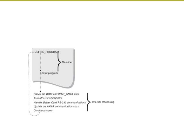
3.At the end of mainline, the Central Controller does some internal processing, then returns to the top of mainline to start another loop (FIG. 1).
FIG. 1 Mainline execution and internal processing
During this time, the Central Controller operations include:
!Checking the WAIT and WAIT_UNTIL lists
!Turning off expired PULSEs
!Handling Central Controller RS-232 communications
!Updating the AXlink communications bus
After the Central Controller handles these tasks, it executes mainline again:
1.First, the Central Controller scans the wait list for any expired WAITs, then checks the WAIT_UNTIL list for any WAIT_UNTIL statement whose conditions have become true. If one of these events has occurred, the Central Controller immediately goes back into the program and executes the statement or compound statement directly following the WAIT or WAIT_UNTIL statement.
2.Next, the Central Controller checks to see if any channels activated by the PULSE keyword need to be turned off. If so, the Central Controller turns them off.
3.Next, the Central Controller handles RS-232 communications. It checks for incoming characters, executes valid commands typed by the user, and sends out any pending information.
4.Finally, the Central Controller updates the AXlink bus. During this time, the Central Controller blinks the green LEDs on all Axcess bus devices, reads pending input changes, and updates all levels and bargraphs. This action must be done frequently or the AXlink bus will stop operating, causing the system to stop working.
|
8 |
Axcess Programming Language |
|
|
|

Axcess Basics
Definition Sections
Starting a new program
When you begin a new program with the New option in the File menu, there are several definition headings indicating what should be defined in each section:
!DEFINE_DEVICE
!DEFINE_CONSTANT
!DEFINE_VARIABLE
!DEFINE_LATCHING
!DEFINE_MUTUALLY_EXCLUSIVE
!DEFINE_START
!DEFINE_PROGRAM
The program will not operate differently if you do not have any statements under a heading. However, you should keep the headings for reference.
Although the definition sections are not used in the main program, they create the materials the main program needs to run. For example, devices and their channels are given names; channels are given different characteristics, and variables are formed in the definition sections. Even the immediate startup procedures of the Axcess Control System are contained in a definition section. If you develop a good understanding of the DEFINE statements, you can build an excellent foundation for the main part of your program.
DEFINE_DEVICE
When you start writing a program, label each device in the system. Each device on AXlink must have a unique device number. For example, card 1 may have device number 1, and card 2 may have device number 2. Whenever you use this device name in your program, Axcess will automatically use the corresponding device number to reference the device. This is the function of the DEFINE_DEVICE section. It is placed at the beginning of the program, and allows you to name the devices.
However, with a long list of devices connected to AXlink, these numbers can be difficult to remember. Assigning actual names to these devices is much easier.
The first step in writing a program is defining the devices in your system. For example, you have a VCR, a CD player, and a cassette deck, and you are controlling them with the first three cards in your CardFrame. These cards have device numbers 1, 2, and 3. You also need to control a projection screen, some drapes, and lights. Two relay cards, one in slot 4 and one in slot 5, will handle these (the first card handles both the screen and drapes). A Touch Panel will be used to control all of these devices. Your DEFINE_DEVICE section should look like this:
The devices included in this code are used for example purposes only. It is not a specific recommendation or endorsement.
Axcess Programming Language |
9 |
|
|
|
|

Axcess Basics
DEFINE_DEVICE |
|
VCR |
= 1 |
CD |
= 2 |
CASS |
= 3 |
RELAY |
= 4 |
LIGHTS |
= 5 |
VPROJ |
= 6 |
TP |
= 128 |
(* AXC-IR/S: VCR *)
(* AXC-IR/S: CD PLAYER *) (* AXC-REL8: VCR *)
(* AXC-REL8: SCREENS AND DRAPES *) (* AXC-REL8: LOW VOLTAGE LIGHTING *) (* AXC-IR/S: PROJECTOR *)
(* AXU-CVA COLOR VIDEO PANEL *)
From this point on, you can reference device 1 with the name VCR, device 2 with the name CD, and so on.
The Push window at the bottom of the screen is changed. If the devices in the previous example are on AXlink, Axcess modifies the window to use the given device name instead of the device's number. This provides a quick reference tool for future programming.
There is one more reason for using DEFINE_DEVICE. When you compare devices using the Compare Current Devices... option in the Diagnostics menu, Axcess checks all the devices listed under DEFINE_DEVICE. Next, it checks which devices are on AXlink. Axcess then tells you the devices that you did not define in your program. These devices cannot be used or referenced until they are defined, so check that all devices are under this heading.
AMX encourages the practice of starting control panel device numbers at device 128. This includes radio frequency (RF) receivers, touch panels, softwire panels, and all other control panels and receivers.
DEFINE_CONSTANT
Constants are identifiers whose values remain unchanged throughout the entire program. The process of defining them is very similar to defining devices. Assigning a value to an identifier in this section locks that value to the identifier for the entire program, making it possible to use descriptive names instead of just numbers in your program.
In your system, the VCR, CD player, and cassette deck devices have channels that activate the various transport functions, such as Play and Stop. As a general rule, Play is usually channel 1 and Stop is channel 2. You could define these channel numbers as constants in your program to make it more readable.
DEFINE_CONSTANT |
|
|
PLAY |
= 1 |
(* VCR, CD AND CASS CONSTANTS *) |
STOP |
= 2 |
|
PAUSE |
= 3 |
|
FFWD |
= 4 |
|
REW |
= 5 |
|
FSRCH |
= 6 |
|
RSRCH |
= 7 |
|
REC |
= 8 |
|
SCREEN_UP |
= 1 |
(* RELAY CONSTANTS *) |
SCREEN_DN |
= 2 |
|
SYSTEM_POWER |
= 3 |
|
DRAPES_OPEN |
= 4 |
|
DRAPES_CLOSE |
= 5 |
|
DRAPES_STOP |
= 6 |
|
AMP_POWER |
= 7 |
|
|
10 |
Axcess Programming Language |
|
|
|

Axcess Basics
LIGHT_FULL |
= 1 |
(* LOW VOLTAGE LIGHTING PRESETS *) |
LIGHT_MED |
= 2 |
|
LIGHT_LOW |
= 3 |
|
LIGHT_OFF |
= 4 |
|
VPROJ_IN_1 |
= 11 |
|
VPROJ_IN_2 |
= 12 |
|
VPROJ_IN_3 |
= 13 |
|
VPROJ_IN_4 |
= 14 |
|
The value of the constant PLAY is now set to 1. Also, STOP has a value of 2. Both of these values cannot be changed anywhere in the program. With these constants set, if you need to activate the play function of the VCR later in your program, use the constant PLAY, and Axcess knows to use channel 1.
More than one constant can have the same number. For example, PLAY and FWD can both equal 1. You may see this if two cards do not have the same channels for the same functions. For example, PLAY on the VCR control card might be channel 1, and FWD on the slide control card could also be channel 1.
By definition, the same constant cannot reference more than one number. This might seem obvious, but this type of error could work its way into larger programs. If you make this mistake, Axcess notifies you with a DUPLICATE SYMBOL error message upon compiling.
DEFINE_VARIABLE
Variables are places to store data that will change as the program is executed. Think of a variable as a random container, nearly anything can be placed in it. For example, a variable can represent any number from 0 to 65,535; variables cannot hold a negative number. If one variable is subtracted from another, the result will always be positive. If you subtract a larger number from a smaller number, the result wraps around at 65,535. For example, 10-20 = 65,525.
DEFINE_VARIABLE |
|
|
TEMP |
(* Single variables *) |
|
BUFFER[1Ø] |
(* |
Array variables *) |
INTEGER CAM_PRESET[1Ø] |
(* |
Integers and variables *) |
When the system is turned off, variables retain their values. Resetting varaiables must be done manually in the DEFINE_START section.
In your first program, you will not be using variables, but keep the DEFINE_VARIABLE header because you will be using them in the future.
DEFINE_LATCHING
A latching channel is a channel that only changes its state once per push. If a latching channel is activated by a TO keyword, it changes its state; when the TO is stopped, by releasing the button that started it, the channel does not go back to its previous state (like a momentary channel). The channel stays either on or off. The status of a latching channel will reflect the on/off state of the channel. Here is an example:
DEFINE_LATCHING |
|
|
|
|
|
[RELAY,SYSTEM_POWER] |
(* |
defined |
as |
latching *) |
|
[VCR,PLAY]..[VCR,REWIND] |
(* |
defines |
a range of device-channels as |
||
|
|
latching *) |
|
|
|
VAR1 |
|
(* defined |
as latching |
*) |
|
Axcess Programming Language |
11 |
|
|
|
|

Axcess Basics
DEFINE_MUTUALLY_EXCLUSIVE
When a channel is turned on in a mutually exclusive set, it activates its physical output as long as the button is pressed. When the button is released, the physical output stops. The status, however, does not work the same way. Even after the physical output stops, the status still indicates the channel is on until another channel in the mutually exclusive set is activated. The status is left on to indicate which channel in the set was last activated. This is sometimes called last button pressed feedback. When a channel or variable in this set is activated, all the other members of the set are turned off beforehand. This is called break before make logic. This prevents an accidental activation of more than one channel at the same time, which could cause serious damage to some devices. Members of a mutually exclusive set are placed in parentheses underneath the DEFINE_MUTUALLY_EXCLUSIVE keyword. The double period (..) shortcut specifies a range of device-channels to be defined as mutually exclusive. For example:
DEFINE_MUTUALLY_EXCLUSIVE
([RELAY,SCREEN_UP],[RELAY,SCREEN_DOWN]) (* defines two channels as mutually exclusive *)
([RELAY,DRAPE_OPEN]..[RELAY,DRAPE_STOP]) (* defines a range of
channels as mutually exclusive *)
DEFINE_START
DEFINE_START marks the section of programming that will be executed only once immediately following power-up or system reset. They cannot be executed again until another Axcess power-up. The keyword TO cannot be used in the DEFINE_START section; instead, use ON, OFF, or PULSE. For information on these keywords, refer to Changing the State of a Channel section on page 16.
When the Axcess Control System is turned on, the program that was last loaded into the Central Controller is in operation, and is waiting for input from the user. However, you can tell Axcess to run a series of statements immediately when the system is turned on.
In your program, you may want to reset all three decks to stop (using SYSTEM_CALLs), turn on the lights, open the drapes, and raise the screen when Axcess is powered up. For example:
DEFINE_START
PULSE[LIGHTS,LIGHT_FULL]
PULSE[RELAY,DRAPES_OPEN]
PULSE[RELAY,SCREEN_UP]
SYSTEM_CALL 'FUNCTION' (VCR,STOP,Ø)
SYSTEM_CALL 'FUNCTION' (CD,STOP,Ø)
SYSTEM_CALL 'FUNCTION' (CASS,STOP,Ø)
Any resetting of variable values should be done in this section. Remember, variables retain their values even if the system is powered down.
DEFINE_PROGRAM
Define_Program marks the beginning of mainline, telling the compiler that the following statements make up the actual executing program. Before beginning the main program, you must have the DEFINE_PROGRAM header. This header tells Axcess you are beginning the actual program at this point. It is used like this:
DEFINE_PROGRAM (* Your program starts here *)
The most important feature of mainline is that it runs in a continuous loop. While most programming languages have a beginning and an end, mainline is like a circle: when the Central
|
12 |
Axcess Programming Language |
|
|
|
Axcess Basics
Controller gets to the end, it loops back to the top and passes through it again, as shown in FIG. 1 on page 8.
PROGRAM_NAME
Axcess uses a long file name to provide a more descriptive name for Axcess programs. Thre file name gets embedded into the program the first time it is saved, and will appear in the first line of the program. For example:
PROGRAM_NAME='long file name goes here'
This name is managed by Axcess and is automatically updated every time the file is saved.
Axcess Programming Language |
13 |
|
|
|
|

Axcess Basics
|
14 |
Axcess Programming Language |
|
|
|
Using Input and Output
Using Input and Output
Channels
You define what happens when remote inputs occur in mainline. To get inputs into the program, and generate an output, use channels.
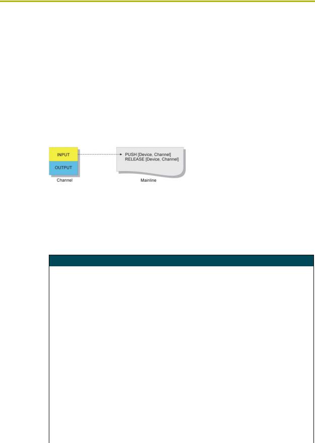
Almost all methods of control using an Axcess Control System require the use of channels on devices, as shown in FIG. 2. Every channel has two aspects: the input function and output function. When a button is pressed on a control panel, the input function of the button sends an input change to your program. The input change alerts the Central Controller to scan your program for a reference to that input.
FIG. 2 Input and output functions of a channel
Input Change Keywords
When there is an input change, Axcess passes through the entire program once to see if the change is referenced. If so, Axcess executes the statements in the program associated with the input change. The following six keywords are used in conjunction with input changes:
Input Change Keywords
PUSH |
The PUSH keyword is used to find out if a channel has had an input change |
|
from off to on, such as when a button is pressed. If the channel has been |
|
turned on, the corresponding PUSH statement is activated. The operation(s) |
|
following this PUSH statement is executed once after the channel is turned on. |
|
PUSH statements must be followed by a device number and a particular chan- |
|
nel, and both are enclosed in brackets. Variables can be used in their places, |
|
but this is done only in special circumstances. Following the PUSH statement |
|
is the operation to be executed when the PUSH occurs. If more than one event |
|
must happen, a compound statement must follow the PUSH. For example: |
|
PUSH[device,channel] |
|
{ |
|
(* Statement *) |
|
} |
|
Multiple PUSH statements can be specified to execute the same action. For |
|
example: |
|
PUSH[TOUCH_PANEL,1] |
|
PUSH[RADIO,64] |
|
{ |
|
(* Statement *) |
|
} |
|
|
RELEASE |
The RELEASE keyword is used in the same way as PUSH, except the opera- |
|
tion underneath a RELEASE statement will be executed if the corresponding |
|
button is released. |
|
|
Axcess Programming Language |
15 |
|
|
|
|
Using Input and Output
Input Change Keywords (Cont.)
PUSH_DEVICE |
PUSH_DEVICE is a system variable containing the number of the device hav- |
|
ing the channel that was just turned on due to an input change. |
|
If a button for device T_PANEL was pressed, PUSH_DEVICE would be equal |
|
to the device number of T_PANEL. This variable is set when a channel is |
|
turned on, and it remains constant for one pass through mainline. If no channel |
|
has been turned on, PUSH_DEVICE will contain Ø. |
|
PUSH_DEVICE and RELEASE_DEVICE cannot both have a non-zero value |
|
during the same pass through mainline. At least one of them will always be |
|
zero. |
|
|
RELEASE_DEVICE |
RELEASE_DEVICE stores the number of the device containing the channel |
|
whose button was most recently released. |
|
If a button for device T_PANEL was released, RELEASE_DEVICE would be |
|
equal to the device number of T_PANEL. This system variable is used in a pro- |
|
gram in the same manner as PUSH_DEVICE. This variable will have the same |
|
value for only one pass through the program. |
|
PUSH_DEVICE and RELEASE_DEVICE cannot both have a non-zero value |
|
during the same pass through mainline. At least one of them will always be |
|
zero. |
|
|
PUSH_CHANNEL |
PUSH_CHANNEL is the same as PUSH_DEVICE, except that the channel |
|
number that was most recently turned on is stored inside the variable. |
|
PUSH_CHANNEL and RELEASE_CHANNEL cannot both have a non-zero |
|
value during the same pass through mainline. At least one of them will always |
|
be zero. |
|
|
RELEASE_CHANNEL |
RELEASE_CHANNEL stores the channel whose button was most recently |
|
released. |
|
This system variable is used in a program in the same manner as |
|
PUSH_CHANNEL. |
|
PUSH_CHANNEL and RELEASE_CHANNEL cannot both have a non-zero |
|
value during the same pass through mainline. At least one of them will always |
|
be zero. |
|
|
Changing the State of a Channel
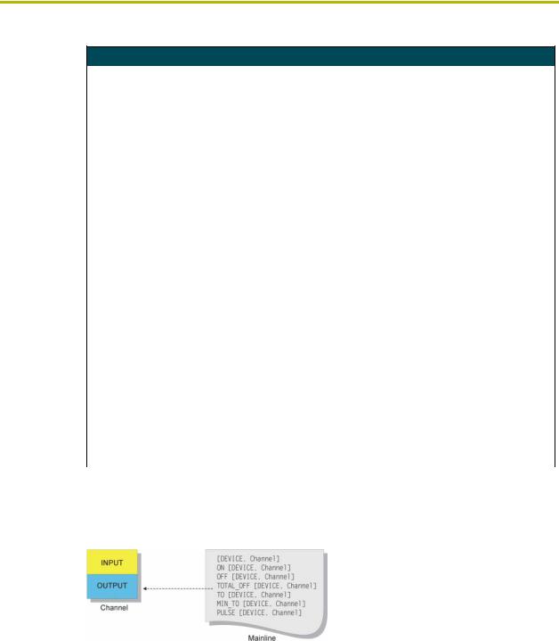
The next series of keywords allows you to activate channels. This activation is called an output change, which is a message to the output function of a channel. See FIG. 3.
FIG. 3 Keywords affecting output changes
Output Change Keywords
When you use an output change keyword to activate a channel in a device, the device starts the operation associated with the channel. For instance, activating channel 5 on a relay card activates relay number 5, whereas activating channel 5 on an infrared/serial card causes it to generate the infrared pattern stored at location 5.
These keywords can be used in conjunction with variables. When a variable is activated with one of these keywords, turning it ON gives it a value of 1, and turning it OFF gives it a value of Ø.
|
16 |
Axcess Programming Language |
|
|
|

Using Input and Output
The output change keywords are described in the table below:
Output Change Keywords
ON |
The ON keyword turns on a channel or variable. |
|
|
If the channel or variable is already on, its status will remain unchanged. Here |
|
|
are two examples: |
|
|
ON [1,2] |
(* Turns on channel 2 of device 1 *) |
|
ON [TEMP] |
(* Sets the value of the variable |
|
|
TEMP to 1 *) |
|
A variable is considered ON if it contains a non-zero number; in this case, the |
|
|
value is 1. If a variable contains the value Ø, it is considered OFF. |
|
|
|
|
OFF |
The OFF keyword turns off a channel or variable. |
|
|
If the channel or variable is already off, its status will remain unchanged. Here |
|
|
are two examples: |
|
|
OFF [1,2] |
(* Turns off channel 2 of device 1 *) |
|
OFF [TEMP] |
(* Sets the value of the variable |
|
|
TEMP to 0 *) |
|
|
|
TOTAL_OFF |
The TOTAL_OFF keyword acts in the same manner as OFF, except that it also |
|
|
turns off the status of a channel or variable that is in a mutually exclusive set. |
|
|
For more information on mutually exclusive sets, refer to Mutually Exclusive on |
|
|
page 20. |
|
|
|
|
TO |
The TO keyword is used to activate a channel or variable for as long as the cor- |
|
|
responding device-channel of its PUSH statement is activated. |
|
|
When the device-channel referenced by the PUSH statement changes from off |
|
|
to on, the TO activates the device-channel or variable in the brackets following |
|
|
it. When the device-channel of its PUSH is released, the TO statement stops |
|
|
activating its devicechannel or variable. For this reason, TO must be placed |
|
|
underneath a PUSH statement. |
|
|
The TO keyword has several conditions: |
|
|
• It must be used only below a PUSH statement. |
|
|
• It cannot be used with the WAIT keyword. For detailed information, refer to |
|
|
Multiple Waits in the Waits and Timer Keywords section. |
|
|
• It cannot be placed in the DEFINE_START section. |
|
|
The channel or variable will act under the rules set by DEFINE_LATCHING, |
|
|
DEFINE_MUTUALLY_EXCLUSIVE, and DEFINE_TOGGLING. For more infor- |
|
|
mation, refer to the Channel Characteristics section. You will learn about these |
|
|
definitions later, when you add more to your program. |
|
|
|
|
MIN_TO |
This keyword operates like the TO keyword, except that the specified channel |
|
|
or variable stays on for a minimum amount of time, even if the corresponding |
|
|
device-channel is released. |
|
|
The time duration is determined by SET_PULSE_TIME. MIN_TO follows the |
|
|
same conditions of operation as the TO keyword. |
|
|
|
|
PULSE |
The PULSE keyword turns on a channel or variable for a certain amount of |
|
|
time. Once the time elapses, the channel or variable is turned off. |
|
|
As an example, refer back to the discussion on DEFINE_START, in the Defin- |
|
|
ing Start section. The PULSE keyword was used to activate a lighting preset, a |
|
|
drapes change, and a screen change. The duration of this PULSE is one half- |
|
|
second, but it can be changed if necessary with the SET_PULSE_TIME key- |
|
|
word. The PULSE time is measured in tenths of seconds, and the Axcess |
|
|
default is one half-second. The PULSE time remains the same value until it is |
|
|
changed in the program. For example: |
|
|
SET_PULSE_TIME(12) |
|
|
This sets the current duration of future PULSEs to 1.2 seconds. It is always a |
|
|
good practice to return pulse time to the default setting of .5 seconds, as shown |
|
|
in the following example: |
|
|
SET_PULSE_TIME(5) |
|
|
|
|
Axcess Programming Language |
17 |
|
|
|
|

Using Input and Output
Direct Assignment
Direct assignment is another method of generating an output change, that does not involve using keywords. Any reference to a device-channel that does not have the keywords PUSH or RELEASE preceding it is a reference to the output side of the channel. Thus, assigning a value directly to a device-channel changes the output of the channel. For example:
[TP,1] = 1
This statement will send an output change to channel 1 of device TP, telling the channel to turn on since Axcess interprets any non-zero number as ON. Putting this statement in mainline will set the channel ON permanently. Using direct assignment is most appropriate in feedback statements. For controlling devices, the keywords ON, OFF, and TO are more appropriate.
Putting Input and Output Together
Combining input and output changes into one statement is the basis of most Axcess programming. Now you have the tools to write the code that will accomplish this. On your touch panel, you will set buttons 1-5 to activate the screen and drape functions. Here is the first section of program code:
DEFINE_PROGRAM |
|
PUSH[TP,1] |
(* SCREEN UP *) |
TO[RELAY,SCREEN_UP] |
|
PUSH[TP,2] |
(* SCREEN DOWN *) |
TO[RELAY,SCREEN_DN] |
|
PUSH[TP,3] |
(* DRAPES OPEN *) |
TO[RELAY,DRAPES_OPEN] |
|
PUSH[TP,4] |
(* DRAPES CLOSE *) |
TO[RELAY,DRAPES_CLOSE] |
|
PUSH[TP,5] |
(* DRAPES STOP *) |
TO[RELAY,DRAPES_STOP] |
|
In this code, there are actually five separate, but similar statements. In each statement, there is the keyword PUSH followed by a device-channel reference, in this case [TP,1]. This tells Axcess to look here if channel 1 on device 128 receives an input change from OFF to ON. If such an input change occurs, the corresponding TO statement executes.
The TO statement tells Axcess that for as long as channel 1 on device 128 is activated, turn on device 1, channel 1.
Remember, TP is a device definition for device 128, and RELAY is a constant with a value of 1, as is SCREEN_UP. Always be precise with the syntax. Use numbers for input channels, and device names for devices, as shown in the example above.
|
18 |
Axcess Programming Language |
|
|
|
Channel Characteristics
Channel Characteristics
This section contains information on channel characteristics and how to change the way the status of an output channel behaves. It includes explanations of channel concepts, and examples of Axcess programming code. In this chapter, you will learn how to change the status behavior, which in turn changes the way a channel reacts when it is activated by the output change keywords.
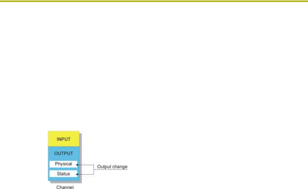
Parts of an Output Channel
An output channel actually has two parts: the physical part and the status part, as shown in FIG. 4.
FIG. 4 Parts of an output channel.
The physical part is the physical device-dependent control, such as a relay on a relay card, a button light (lamp) on a Touch Panel, or an infrared pattern in an infrared card. The status reports the state of the physical part. Typically, these two parts act exactly the same; when one is on, so is the other.
The Device-Channel Concept
Everything that an Axcess Control System controls is controlled through a device in the system. Each device communicates to the Central Controller through AXlink, the Axcess Control System's communication bus. Most devices, such as a Touch Panel or a relay card, have channels which either generate an input, accept an output, or both. These inputs and outputs are referred to in the Axcess program as a device-channel, which is written like this:
TO[DEVICE,Channel]
This the device-channel is the most fundamental concept of the Axcess Control System, as it is the most common way that Axcess communicates to the outside world.
Defining Latching
The default status of all channels is momentary. When a momentary channel is activated with a TO keyword, it activates its output and status only as long as the button which activated the TO keyword is pressed. For example, the Focus channel for slide projectors is momentary. When the corresponding Focus button is pressed, the slide projector will focus. The projector will continue to do so until the button is released.
However, some devices need their particular channel to stay ON to operate. If so, the channel can be made latching by being placed in the DEFINE_LATCHING section. Once a latching channel is activated by a TO keyword, the channel changes its state from OFF to ON (assuming it was previously off). However, when the TO keyword stops activating the channel (its corresponding
Axcess Programming Language |
19 |
|
|
|
|

Channel Characteristics
button is released), the channel does not go back to OFF (like a momentary channel), it stays ON. It only returns to OFF when the channel is reactivated by a TO keyword. As a result, the status of a latching channel reflects the true ON/OFF state of the channel.
In your program, RELAY is already defined as device number 4 and SYS_POWER is defined as a constant having the value 3. Using these two values together as device-channel [RELAY,SYS_POWER] gives you a relay to use for your system's power control. You will need to make this relay latching so that it stays on after you release the Touch Panel button. Also, your drape motor needs latched relays to operate. Here are the definitions:
DEFINE_LATCHING
[RELAY,SYSTEM_POWER]
If you have a series of consecutive channels to be defined, you can use double periods (..) as a shortcut. The use of double periods will specify a range of channels between the first and last channel. For example, if the lights in your system need latched relays to operate, instead of defining each one right after the other, follow this example:
[LIGHTS,LIGHT_FULL]..[LIGHTS,LIGHT_OFF]
In your DEFINE_CONSTANT section, you defined these constants as 1 through 4, so this will make relays 1 through 4 on the LIGHTS card (card 5) latching.
Mutually Exclusive
Channels can also be defined as mutually exclusive. A mutually exclusive group is a set of channels in which only one channel of the set can be turned on at a time. The three kinds of mutually exclusive channels are momentary, latching, and toggling. They are each described below:
Defining momentary mutually exclusive
When a channel is turned on in a momentary mutually exclusive set, it activates its physical output as long as the button is pressed. When the button is released, the physical output stops. The status, however, does not work in the same manner. Even after the physical output stops, the status still indicates that the channel is on until another channel in the mutually exclusive set is activated. The status is on to let you know which channel in the set was last activated. This is sometimes called last button pressed feedback.
Be sure to find out which devices need mutually exclusive channels. Do not wait until you test the program, as you could damage some devices.
When a channel or variable in this set is activated, all the other members of the set are turned off beforehand. This is called break before make logic. This prevents accidental activation of more than one channel at the same time, which could cause serious damage to some devices.
For example, consider the drape and screen channels of the device RELAY. Since you cannot open and close a drape all at once, and you cannot raise a screen and lower it at the same time, only one channel can be turned on at any time. They must be defined as mutually exclusive. When SCREEN_UP is activated, the SCREEN_DOWN channel is turned off and SCREEN_UP turns on. The corresponding SCREEN_UP status stays on even though the relay is de-energized when the button is released. When SCREEN_DOWN is activated, SCREEN_UP is turned off. The SCREEN_DOWN status is now the only status turned on.
|
20 |
Axcess Programming Language |
|
|
|

Channel Characteristics
Once a channel has feedback in a mutually exclusive group, there will always be one channel with its status on in that group, unless it is turned off with TOTAL_OFF.
You will also define the lighting relays as mutually exclusive so that you can utilize last button pressed logic when you program the feedback for these buttons. This will allow the user to look at the panel and know which lighting preset was activated last.
Members of a mutually exclusive set are placed in parentheses underneath the DEFINE_MUTUALLY_EXCLUSIVE keyword. The double period (..) shortcut explained in the latching section is also applicable here. For example:
DEFINE_MUTUALLY_EXCLUSIVE ([RELAY,SCREEN_UP],[RELAY,SCREEN_DN]) ([RELAY,DRAPES_OPEN],[RELAY,DRAPES_CLOSE],[RELAY,DRAPES_STOP]) ([LIGHTS,LIGHT_FULL]..[LIGHTS,LIGHT_OFF])
The first set defines the two screen channels as mutually exclusive. Using the shortcut, the second set defines the three drape channels as mutually exclusive, and the third set defines the four lighting relays as mutually exclusive.
Defining mutually exclusive latching
A mutually exclusive channel can have its physical output continually on if necessary. This is done by defining a channel as both mutually exclusive and latching, resulting in the description mutually exclusive latching. If you define a channel in this manner, the physical output remains on until another button in its mutually exclusive set is pressed.
The status of a mutually exclusive latching channel behaves in the same manner as that for a mutually exclusive momentary channel. Note that the physical part and the status of a mutually exclusive latching channel operate in the same manner.
In your program, the lighting relays are already defined as latching. However, you also want them to have the characteristics of a mutually exclusive set so that only one lighting mode can be on at one time. Thus, you would also place the device-channels of these relays in the DEFINE_MUTUALLY_EXCLUSIVE section:
DEFINE_MUTUALLY EXCLUSIVE
([LIGHTS,LIGHT_FULL]..[LIGHTS,LIGHT_OFF])
Defining mutually exclusive toggling
When a channel is defined as mutually exclusive latching, there is no way to turn off the channel without activating another. Mutually exclusive toggling allows a channel to be turned on or off by successive presses of the same button, just like a normal latching channel. Also, the channel is still affected by its mutually exclusive characteristics; if the channel is on, it can be turned off by another activated channel in its mutually exclusive set. The status of a mutually exclusive toggling button operates in the same way as that for a mutually exclusive latching button.
To make a channel toggling, it must be defined as mutually exclusive and toggling in both the DEFINE_MUTUALLY_EXCLUSIVE and DEFINE_TOGGLING sections. In your program, the screen relays are both mutually exclusive and latching, so there is no way to turn off a screen relay without turning on the other. You could fix this by defining the screen relays as mutually exclusive toggling:
Axcess Programming Language |
21 |
|
|
|
|

Channel Characteristics
DEFINE_TOGGLING
[RELAY,SCREEN_UP]
[RELAY,SCREEN_DOWN]
Putting it all to work
Now that you know how all these different types of channels operate, proceed to the mainline section of the program and add the following lines to activate your system power, screen, drape, and lighting relays:
DEFINE_PROGRAM |
|
PUSH[TP,8] |
(* POWER ON/OFF *) |
TO[RELAY,SYSTEM_POWER] |
|
PUSH[TP,1] |
(* SCREEN UP *) |
TO[RELAY,SCREEN_UP] |
|
PUSH[TP,2] |
(* SCREEN DOWN *) |
TO[RELAY,SCREEN_DN] |
|
PUSH[TP,3] |
(* DRAPES OPEN *) |
TO[RELAY,DRAPES_OPEN] |
|
PUSH[TP,4] |
(* DRAPES CLOSE *) |
TO[RELAY,DRAPES_CLOSE] |
|
PUSH[TP,5] |
(* DRAPES STOP *) |
TO[RELAY,DRAPES_STOP] |
|
PUSH[TP,9] |
(* LIGHTS FULL *) |
TO[LIGHTS,LIGHT_FULL] |
|
PUSH[TP,1Ø] |
(* LIGHTS MEDIUM *) |
TO[LIGHTS,LIGHT_MED] |
|
PUSH[TP,11] |
(* LIGHTS LOW *) |
TO[LIGHTS,LIGHT_LOW] |
|
PUSH[TP,12] |
(* LIGHTS OFF *) |
TO[LIGHTS,LIGHT_OFF] |
|
This section accomplishes several tasks:
!Pressing button number 8 on the Touch Panel alternately latches and unlatches the SYSTEM_POWER channel (channel 1) on card RELAY.
!A press of the Screen Up button latches on the SCREEN_UP channel on device RELAY, after unlatching SCREEN_DN. The Screen Down button acts the same way as the Screen Up button, but with the opposite channels.
!Pressing Drapes Open or Drapes Close does several things. If it is off, it makes sure the other drape channel is off (due to its mutually exclusive relationship), then it latches on. If it was on, it turns off, but leaves its status on. To turn off the status of a channel in a mutually exclusive group, use the TOTAL_OFF keyword.
!Since the LIGHTS channels are mutually exclusive latching, a press of the Lights Full button latches on the LIGHT_FULL channel on the device LIGHTS, after unlatching any LIGHTS channel that was previously on. The other LIGHTS channels operate in a similar fashion.
!The DRAPES_STOP channel is momentary mutually exclusive, whereas the other drape channels are mutually exclusive latching. When the Drapes Stop button is pressed, Axcess makes sure the other drape channels are off, then engages the DRAPES_STOP
|
22 |
Axcess Programming Language |
|
|
|
Loading...