


SURTA1500XLJ
Table of contents
 Loading...
APC Smart-UPS® RT SURTA1500XL/SURTA1500XLJ/SURTA2000XL
Uninterruptible Power Supply User Manual
Introduction/Before Installation
About this Manual
The APC Smart-UPS® RT (SURTA1500XL, SURTA1500XLJ, and SURTA2000XL) is a high-
performance, Uninterruptible Power Supply (UPS) designed to prevent blackouts, brownouts, sags
and surges from reaching your computers, servers, and other sensitive electronic equipment.
This manual describes procedures on how to properly unpack and install the UPS, connect the battery
and equipment, configure accessories, and start up the system.
Illustrations are representative. Your configuration, including components and optional APC equipment, may be different from the models shown in this manual. The user manual is accessible from the
supplied CD and the APC web site, www.apc.com.
Contact Information
Refer to www.apc.com to contact APC or for additional information about this product.
Safety Information
Read the Safety Guide before you begin the installation, operate the UPS, or
perform equipment maintenance. Failure to comply with safety instructions
Warning
Unpacking and Equipment Placement
could result in bodily injury or equipment damage.
The UPS is heavy. Two people are required to lift the UPS.
Select a location sturdy enough to handle the weight of the UPS.
Heavy
1. Unpack the equipment. The packaging is recyclable; save it for reuse or dispose of it properly.
2. Inspect the equipment upon receipt. Notify the carrier and dealer if there is damage.
3. Check the package contents:
• UPS and front bezel
• UPS literature kit containing:
– product documentation
– safety information
– warranty information
4. Place the UPS where it will be used.
– Ensure that air vents on the front and rear of the UPS are not blocked.
120 V models:
•PowerChute® CD
• Serial and USB
communication
cables
100 V models:
• Serial
communication
cable

Installation
– Do not operate the UPS where there is excessive dust or the temperature or humidity are
outside the specified limits.
2.5
cm
2.5
cm
40°C
104°F
95%
0%
Installation
Refer to instructions below for information on how to install the UPS in a rack, as a tower configuration, or when installing the UPS with optional battery pack(s). Once the UPS has been placed in the
desired tower or rack location, complete the remaining installation steps in sequential order, beginning
with “Connect Equipment to the UPS” on page 2.
To Install the UPS in a Rack
See the installation sheet supplied with the optional rail kit (SURTRK) to install the UPS in the rack. It
is recommended that you remove the battery before attempting to install it in the rack. See “Battery
Replacement Instructions” on page 11 for the procedure.
To Install the UPS as a Tower Configuration
For stability, the UPS is shipped with stabilizing feet. Removal of the feet in a
Caution
To Install the UPS with External Battery Pack(s)
In addition to the UPS, if your configuration includes optional Smart-UPS RT battery pack(s)
(SURTA48XLBP or SURTA48XLBPJ), see the battery pack user manual to complete the physical
installation for the UPS with external battery pack(s).
The UPS must be installed above external battery pack(s) when in a rack. When installing the UPS as
a tower configuration, battery pack(s) must be installed to the right of the UPS when facing the front
of the UPS. Failure to follow these instructions could result in cabling shortage.
Connect Equipment to the UPS
tower configuration may result in bodily injury or equipment damage.
Prior to connecting the grounding cable, ensure that the UPS is NOT connected to
Caution
utility or battery power circuits. See step 3 on page 3 for procedure.
The UPS is equipped with the following connectors.
Connectors Type Description
Serial Com Use only the supplied cable to connect to the serial port.
N
OTE: A standard serial interface cable is incompatible with the UPS.
USB Com 100 V Models: Users may purchase software and cables as an accessory
to the UPS. Refer to the APC web site, www.apc.com for information
on accessories.
NOTE: Serial and USB ports cannot be used simultaneously.
2 Smart-UPS RT SURTA1500XL/SURTA1500XLJ/SURTA2000XL Uninterruptible Power Supply User Manual
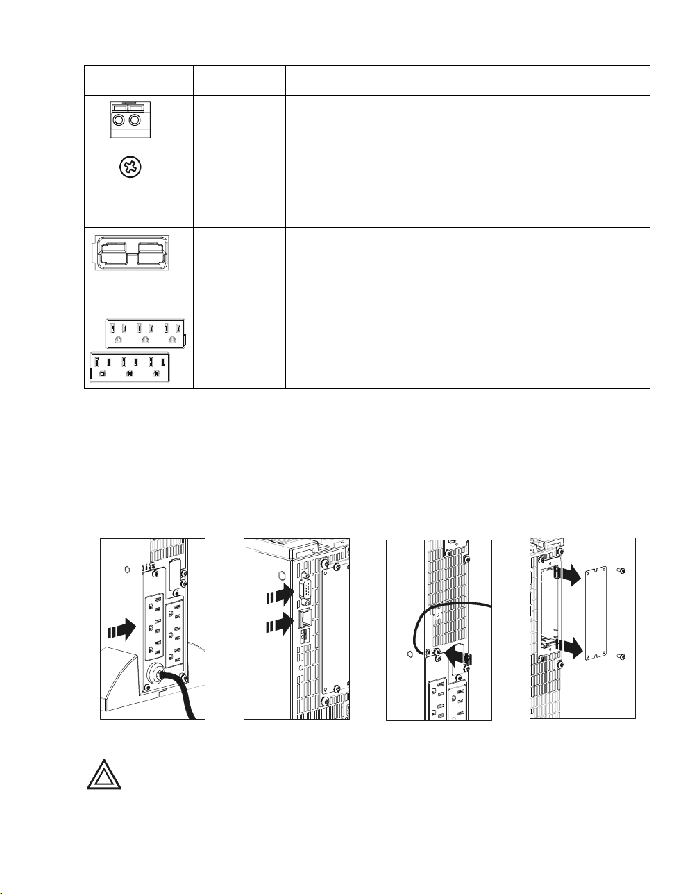
Connectors Type Description
EPO terminal The Emergency Power Off (EPO) terminal allows the user to connect
the UPS to the central EPO system.
NOTE: Adhere to national and local codes when wiring the EPO switch.
Installation
TVSS screw The UPS features a Transient Voltage Surge-suppression (TVSS) screw
External battery
pack connector
PDU Receptacles Connect equipment to the Power Distribution Unit (PDU) receptacles on
located on the rear panel, for connecting the ground cable on surge suppression devices such as telephone and network line protectors.
N
OTE: Prior to connecting the grounding cable, disconnect the UPS
from the utility power outlet and turn off the UPS.
Optional Smart-UPS RT external battery packs provide extended runtime during power outages. These units support up to ten external battery packs.
N
OTE: See the APC web site, www.apc.com for information on the
external battery pack, SURTA48XLBP or SURTA48XLBPJ.
the rear of the UPS.
1. Connect equipment to PDU receptacles .
2. If applicable, connect equipment to the serial or USB com port .
3. Connect ground cable of voltage surge-suppression equipment or the optional Smart-UPS RT
battery pack to the TVSS screw .
4. Add optional accessories to the Smart-Slot .
a. Remove the cover and screws. Discard or save cover. Do not attempt to reinstall it.
b. Refer to the accessory manual to install equipment.
If Required, Connect the Emergency Power Off (EPO) Feature
The EPO interface is a safety extra low voltage (SELV) circuit. Connect it only to other
SELV circuits. To avoid damage to the UPS, do not connect the EPO interface to any
Caution
Smart-UPS RT SURTA1500XL/SURTA1500XLJ/SURTA2000XL Uninterruptible Power Supply User Manual 3
circuit other than a closure type circuit, properly isolated from the utility.
Installation
The EPO feature provides immediate de-energizing of the UPS and connected equipment from a
remote location, without switching to battery operation.
1. Use one of the following cable types to connect the UPS to the EPO switch.
– CL2: Class 2 cable for general use.
– CL2P: Plenum cable for use in ducts, plenums, and other spaces used for environmental air.
– CL2R: Riser cable for use in a vertical run in a floor-to-floor shaft.
– CLEX: Limited use cable for use in dwellings and for use in raceways.
– For installation in Canada: Use only CSA certified, type ELC (extra-low voltage control
cable).
– For installation in other countries: Use standard low-voltage cable in accordance with national
and local regulations.
2. Locate the EPO connector on the rear of the UPS. Use a normally-open contact to connect
cable to each EPO terminal .
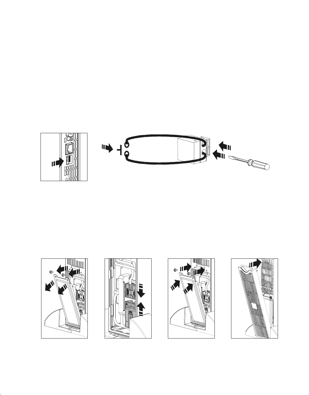
Connect the Battery and Install the Front Bezel
The battery is shipped in the disconnect position. Do not connect the battery until you are ready to use
the equipment.
1. Remove the battery cover .
2. Remove the warning label and protective sticker from the battery connector. Place the sticker on
the back of the battery cover for re-use.
3. Snap the battery connectors together .
4. Reinstall the battery cover .
5. Install the front bezel .
4 Smart-UPS RT SURTA1500XL/SURTA1500XLJ/SURTA2000XL Uninterruptible Power Supply User Manual
Terminal Mode Configuration
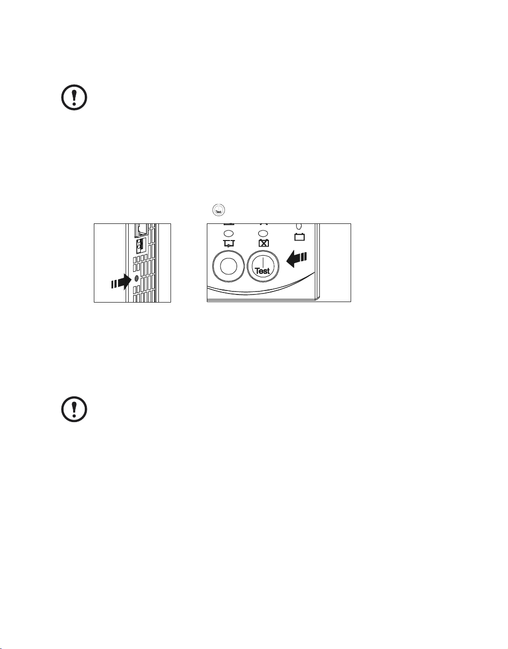
Connect Power and Start Up the UPS
The UPS battery charges when it is connected to utility power and will charge to 90%
capacity within three hours. Do not expect full battery run capability from a new battery or after On Battery operation (see “On Battery Operation” on page 7) until the
battery recharges.
Note
To use the UPS as a master ON/OFF switch, ensure all connected equipment is
switched on. The equipment will not be powered until the UPS is turned on.
1. Plug the UPS into a two-pole, three-wire, grounded receptacle only. Avoid using extension cords.
a. Check to ensure that the Site Wiring Fault LED light on the back of the UPS is NOT
illuminated (On position).
b. If the LED light is on, the outlet is incorrectly wired. Check with a licensed electrician to
ensure that the outlet is properly wired.
2. To power up the UPS, press the button on the front panel.
3. Turn on all connected equipment.
For Additional Computer System Security
For additional computer system security, install PowerChute® Business Edition Smart-UPS® monitoring software. Refer to the software CD included in the literature kit for instructions.
Terminal Mode Configuration
Terminal mode can only be used with the serial cable. If using a USB cable, disconnect
the USB cable from the UPS, and connect the serial cable to the UPS before using the
terminal program.
Note
Shown below is an example of how to use terminal mode to configure the number of external battery
packs. See “Configuration Settings” on page 8 for additional information.
1. Exit the PowerChute Business Edition software.
a. From the windows PC desktop, select START => Settings => Control Panel => Administrative
Tools => Services.
b. Select APC PCBE Server and APC PCBE Agent. Right click the mouse and select Stop.
2. Open a terminal program. Example: HyperTerminal
From the computer desktop, select START => Programs => Accessories => Communication =>
HyperTerminal.
3. Double-click the HyperTerminal icon.
a. Follow the prompts to choose a name and select an icon. Disregard the message, “...must
install a modem,” if it is displayed. Click OK.
Smart-UPS RT SURTA1500XL/SURTA1500XLJ/SURTA2000XL Uninterruptible Power Supply User Manual 5
Loading...