


|
ADG-530 |
Hot Surface Ignition (HSI) System |
|
|
Technical Manual |
|
American Dryer Corporation |
|
88 Currant Road |
|
Fall River MA 02720-4781 |
|
Telephone: (508) 678-9000 / Fax: (508) 678-9447 |
|
E-mail: techsupport@amdry.com |
032197MFM/abe |
ADC Part No. 450401 |

Retain This Manual In A Safe Place For Future Reference
American Dryer Corporation products embody advanced concepts in engineering, design, and safety. If this product is properly maintained, it will provide many years of safe, efficient, and trouble-free operation.
ONLY properly licensed technicians should service this equipment.
OBSERVE ALL SAFETY PRECAUTIONS displayed on the equipment or specified in the installation/operator's manual included with the dryer.
THE HSI MODULEIS NOT FIELD REPAIRABLE
and
THE HSI GAS VALVE IS NOT FIELD REPAIRABLE
We have tried to make this manual as complete as possible and hope you will find it useful. ADC reserves the right to make changes from time to time, without notice or obligation, in prices, specifications, colors, and material, and to change or discontinue models.
WARNING: UNDER NO CIRCUMSTANCES should the door switch or the heat circuit devices ever be disabled.
WARNING: The dryer must never be operated with any of the back guards, outer tops, or service panels removed. PERSONAL INJURY or FIRE COULD RESULT.
NOTE: The wiring diagram for the dryer is located on the right wall, inside the Left Coin Panel area.
Replacement parts can be obtained from your distributor or the ADC factory. When ordering replacement parts from the factory, you can FAX your order to ADC at (508) 678-9447 or telephone your orders directly to the ADC Parts Department at (508) 678-9010. Please specify the dryer model number and serial number in addition to the part number and part description, so that your order is processed accurately and promptly.
The illustrations on the following pages may not depict your particular dryer exactly. The illustrations are a composite of the various dryer models. Be sure to check the descriptions of the parts thoroughly before ordering.
INSTRUCTIONS TO BE FOLLOWED IN THE EVENT THE USER SMELLS GAS MUST BE POSTED IN A PROMINENT LOCATION. THE INSTRUCTIONS TO BE POSTED SHALL BE OBTAINED FROM THE LOCAL GAS SUPPLIER.

GAS “HOT SURFACE IGNITION” (HSI) SYSTEM
MODEL TRITON 2465 (ADC Part No. 128974) 50/60 Hz TYPE ONLY
PRODUCT INFORMATION and TROUBLESHOOTING GUIDE
NOTE: Failure to read and follow ALL instructions and information included in this manual carefully before operating and/or servicing this system, COULD CAUSE PERSONAL INJURY and/or PROPERTY DAMAGE.
IMPORTANT: We have tried to make this manual as complete as possible and hope you will find it useful. However, since the time of this printing, some information contained herein may have been updated.
ADC RESERVES THE RIGHT TO MAKE CHANGES FROM TIME TO TIME, WITHOUT NOTICE or OBLIGATION IN PRICES, SPECIFICATIONS, COLORS, and MATERIALS, and TO CHANGE or DISCONTINUE MODELS or PARTS.
Table of Contents |
|
A. INTRODUCTION ...................................................................................... |
2 |
B. GENERAL SYSTEM INFORMATION ................................................. |
2 thru 5 |
HSI System Components/Functions ................................................. |
2 |
Failure To Light - LOCKOUT ...................................................................... |
2 and 3 |
Flame Failure Reignition ................................................................................ |
3 and 4 |
System (basic) Electrical Ratings/Specifications ............................. |
4 |
C. HSI (Hot Surface Ignition) SYSTEM OPERATION ............................ |
5 thru 7 |
HSI System Operation ...................................................................... |
5 and 6 |
HSI System Operation (Flow Chart) ................................................... |
6 |
Normal Operation (summary) ............................................................. |
7 |
D. TROUBLESHOOTING ............................................................................ |
7 thru 13 |
Test Equipment ........................................................................................ |
8 |
HSI Troubleshooting Terms (definitions) ........................................ |
8 and 9 |
Troubleshooting/System Diagnosis (detailed) .................................... |
9 thru 13 |
E. PARTS LIST (basic) ................................................................................................. |
14 and 15 |
1
A. INTRODUCTION
The Hot Surface Ignition (HSI) System operates at 24 VAC and is a discrete component based gas ignition control (HSI module) system which utilizes a Hot Surface Ignitor as an ignition source. Safe proof of flame is accomplished through flame rectification.
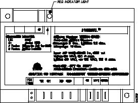
The HSI module has a diagnostic LED (light emitting diode) indicating light which simplifies troubleshooting in the event of a fault.
Other Features...
∙24 VAC microprocessor based HSI control
∙System diagnostic L.E.D. (light emitting diode)
∙Automatic reset one (1) hour after lockout
∙Multiple tries
∙Custom pre-purge and inter-purge timing
∙Remote and local sensing
∙Flame sense test pins
∙Software conforms to “UL 1998” requirements
∙Design certified to ANSI Z21.20 and CAN/CSA C22.2 No. 199-M89
B.GENERAL SYSTEM INFORMATION
1.HOT SURFACE IGNITION (HSI) SYSTEM COMPONENTS/FUNCTIONS:
a.The HSI MODULE is designed to be the “controller” of the HSI system. When activated by the dryer’s controls, this module constantly monitors and controls the functions of the
HSI system (i.e., ignitor activation, gas valve on/off functions, flame verification, etc.), can be operated at either 50 Hz or 60 Hz; and has self diagnostic capabilities.
The L.E.D. (indicator light) on the HSI module simplifies the troubleshooting procedure in the event of a fault within the HSI system. If the LED on the HSI module does not blink constantly, then the system is functioning properly. A “red” L.E.D. (LOCKOUT MODE) indicates that ignition flame has not been confirmed. Refer to the
TROUBLESHOOTING SECTION of this manual for specific diagnostic information.
Hot Surface Ignition (HSI) Module
1)Failure To Light - LOCKOUT
a)Should the main burner fail to light, or if a flame is not detected during the first trial for ignition period, the gas valve is de-energized and the HSI module goes through an inter-purge delay before another ignition attempt. The control will attempt two (2) additional ignition trials before going into LOCKOUT and the gas valve will be de-energized immediately.
2

(1)Recovery from LOCKOUT requires a manual reset by either resetting the thermostat or removing the 24 VAC from the HSI module for a period of five
(5)seconds.
(2)If the microprocessor (computer) is still calling for heat after one (1) hour, the HSI module will automatically reset and attempt to ignite the burner again.
2)Flame Failure Reignition
a)If the established flame signal is lost while the burner is operating, the HSI module will respond within 0.8 seconds. The gas valve is de-energized, the HSI module resets and starts a new ignition sequence in an attempt to relight the burner. If the burner does not light, the HSI module will de-energize the gas valve. The HSI module will make two (2) more attempts to relight the burner. If the burner does not relight, the HSI module will go into LOCKOUT. If flame is reestablished, normal operation resumes.
IMPORTANT: The HSI MODULE is a precision instrument, and should be handled carefully. ROUGH HANDLING or DISTORTING COMPONENTS COULD CAUSE THE MODULE TO MALFUNCTION.
WARNING: THE HSI MODULE IS NOT FIELD REPAIRABLE.
NOTE: To reset the HSI MODULE if it is in the LOCKOUT MODE, open and close the main door then restart the dryer. If the module repeatedly goes into LOCKOUT, refer to the TROUBLESHOOTING SECTION of this manual.
b)The 24 VAC TRANSFORMER is designed to step down the operating (primary) voltage of the dryer from 120 VAC, 208 VAC, or 240 VAC to the 24 VAC (secondary voltage) which is necessary to operate the HSI system and in some cases the controls of the dryer.
The 24 VAC TRANSFORMER has multi-primary taps which allow for one (1)transformer to be used for any voltage application including...120 volt, 208 volt, or 240 volt. Refer to the SERVICE INFORMATION SECTION of this manual for specific transformer/wiring termination information.
24 VAC Transformer
3

c.The HOT SURFACE IGNITOR/FLAME SENSOR ASSEMBLY is located in the burner flame area and is used to ignite the gas by the use of a HOT SURFACE IGNITOR. To provide feedback information to the HSI module a FLAME SENSOR is used to determine whether the burner flame is evident (on).
The HOT SURFACE IGNITOR is a silicon carbide ignitor that upon application of 24 VAC will glow bright orange for the inter-purge time period. The proper location of the silicon carbide ignitor is very important to achieve optium system performance for both ignition and flame sensing.
After the inter-purge period the gas valve will open.
Upon ignition, the resistance in the flame sensor electrode changes and the information is sent to the HSI module via the sensor probe lead connection to the module. Once the resistance is changed and sensed, the HSI module will sustain the gas flow (provide 24 VAC power to the gas valve).
Upshot Burner Tube
with Hot Surface Ignitor (HSI)/Flame Sensor Assembly
d.The HSI 24 VAC GAS VALVE(s) used are of the redundant type which means the gas valve is actually two gas valves in one; one in series with the other. This is a safety feature which provides protection against gas flow in the event of a failure of one of the valves to seat properly. Other features are that the gas valves have a manual shut off, a pressure tap outlet, and are designed for easy conversion to regulated L.P. gas.
36E Redundant Gas Valve
WARNING: THE HSI GAS VALVES ARE NOT FIELD REPAIRABLE.
IMPORTANT: THERE ARE NO PARTS AVAILABLE FOR FIELD REPAIR. Replace gas valve only with exact model and/or type number as noted on gas valve.
4
 Loading...