


SUPER AD-30 Parts Manual
24 VAC Phase 5
1994 thru 2000
MODELS: ADG-30DS
ADE-30S
ADS-30S
American Dryer Corporation
88 Currant Road
Fall River, MA 02720-4781
Telephone: (508) 678-9000 / Fax: (508) 678-9447
E-mail: techsupport@amdry.com
www.amdry.com
091701WM/mcronan |
ADC Part No. 450144 |

Retain This Manual In A Safe Place For Future Reference
American Dryer Corporation products embody advanced concepts in engineering, design, and safety. If this product is properly maintained, it will provide many years of safe, efficient, and trouble-free operation.
ONLY qualified technicians should service this equipment.
OBSERVE ALL SAFETY PRECAUTIONS displayed on the equipment or specified in the installation/operator's manual included with the dryer.
The following “FOR YOUR SAFETY” caution must be posted near the dryer in a prominent location.
FOR YOUR SAFETY
Do not store or use gasoline or other flammable vapors or liquids in the vicinity of this or any other appliance.
POUR VOTRE SÉCURITÉ
Ne pas entreposer ni utiliser d’essence ni d’autres vapeurs ou liquides inflammables dans le voisinage de cet appareil ou de yout autre appareil.
We have tried to make this manual as complete as possible and hope you will find it useful. ADC reserves the right to make changes from time to time, without notice or obligation, in prices, specifications, colors, and material, and to change or discontinue models.
Important
For your convenience, log the following information:
DATE OF PURCHASE |
|
MODEL NO. |
SUPER AD-30 |
|
DISTRIBUTORS NAME |
|
|
|
|
Serial Number(s) |
|
|
|
|
|
|
|
|
|
|
|
|
|
|
Replacement parts can be obtained from your distributor or the ADC factory. When ordering replacement parts from the factory, you can FAX your order to ADC at (508) 678-9447 or telephone your orders directly to the ADC Parts Department at (508) 678-9000. Please specify the dryer model number and serial number in addition to the description and part number, so that your order is processed accurately and promptly.
The illustrations on the following pages may not depict your particular dryer exactly. The illustrations are a composite of the various dryer models. Be sure to check the descriptions of the parts thoroughly before ordering.
“IMPORTANT NOTE TO PURCHASER”
Information must be obtained from your local gas supplier on the instructions to be followed if the user smells gas. These instructions must be posted in a prominent location near the dryer.
Table of Contents
Control DoorAssembly Without Trim ...................................................................................................... |
3 |
High Security Control DoorAssembly ..................................................................................................... |
4 |
Phase 5 Coin Microprocessor Control PanelAssembly ........................................................................... |
5 |
Phase 5 OPL Microprocessor Control Panel Assembly .......................................................................... |
6 |
Phase 5 OPL and Coin Microprocessor Control Box Assembly .............................................................. |
7 |
Coin Vault Assembly .............................................................................................................................. |
8 |
Dual Timer “Tap Touch” Controls ............................................................................................................ |
9 |
DualTimer Control PanelAssembly ...................................................................................................... |
10 |
DualTimer Control BoxAssembly ........................................................................................................ |
11 |
Non-Microprocessor Coin Meter Control PanelAssembly .................................................................... |
12 |
Non-Microprocessor Coin Meter Control BoxAssembly ...................................................................... |
13 |
Slide Meter CaseAssembly .................................................................................................................. |
14 |
Slide Meter Control Box ....................................................................................................................... |
15 |
Coin Meter Replacement Parts ............................................................................................................. |
16 |
LintTrapAssembly ............................................................................................................................... |
17 |
Drop Lint DoorAssembly Without Trim ................................................................................................ |
18 |
Drop Lint DoorAssembly ............................................................................................................... |
19, 20 |
Main Door “Steel”Assembly ................................................................................................................ |
21 |
Plastic Main DoorAssembly ................................................................................................................. |
22 |
Main Door SwitchAssembly Cold Rolled Steel (CRS) Door ................................................................. |
23 |
Plastic Main Door SwitchAssembly ...................................................................................................... |
24 |
Cold Rolled Steel (CRS) Door Front Panel ........................................................................................... |
25 |
Plastic Door Front PanelAssembly ....................................................................................................... |
26 |
Basket (Tumbler)/SupportAssemblies ................................................................................................... |
27 |
Basket (Tumbler) BearingAssembly ................................................................................................ |
28, 29 |
Idler BearingAssembly ................................................................................................................... |
30, 31 |
Non-Reversing Totally Enclosed, Fan-Cooled (T.E.F.C.) Motor MountAssembly ........................... |
32, 33 |
Reversing Totally Enclosed, Fan-Cooled (T.E.F.C.) Motor MountAssembly ................................... |
34, 35 |
Sensor BracketAssemblies ............................................................................................................. |
36, 37 |
Direct Spark Ignition (DSI) BurnerAssembly .................................................................................. |
38, 39 |
Electric OvenAssembly .................................................................................................................. |
40, 41 |
Single-Phase (3ø) Motor, Electric Relay Panel Assembly ...................................................................... |
42 |
3-Phase (3ø) Motor, Electric Relay PanelAssembly .............................................................................. |
43 |
Microprocessor Reversing Rear Control BoxAssembly ......................................................................... |
44 |
Dual Timer Reversing Rear Control BoxAssembly ................................................................................ |
45 |
Steam Coil/Air Operated Steam DamperAssembly ......................................................................... |
46, 47 |
Steam Coil/Mechanical Steam DamperAssembly ............................................................................ |
48, 49 |
SailSwitch/Hi-LimitAssembly .............................................................................................................. |
50 |
Outer Top/Back GuardAssembly ......................................................................................................... |
51 |
CoinAcceptor Listing ........................................................................................................................... |
52 |
Step Down Transformer Usage Listing for Gas/Steam Dryers ................................................................ |
53 |
Transformer Usage Listing for Electric Dryers ........................................................................................ |
54 |
Electric Oven ComponentApplication Chart ......................................................................................... |
55 |
Additional PartsAvailable ..................................................................................................................... |
56 |
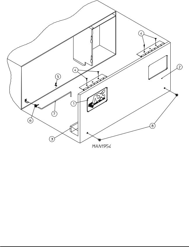
Control Door Assembly Without Trim |
3 |
|
|
For OPL (Non-Coin) Models Mfd. as of July 19, 1999 |
|
|
|
|
|
|
|
|
|
|
|
|
|
|
|
|
|
|
|
|
|
|
|
Illus. No. |
Part No. |
Qty. |
Description |
1 |
881053 |
1 |
ADC Logo ONLY (with double adhesive tape) |
|
870011 |
1 |
Logo Double Adhesive Tape Kit ONLY |
2 |
883097* |
1 |
Control Door |
|
|
|
(includes illus. nos. 2 and 3) |
|
883120 |
1 |
Stainless Steel Control Door |
|
|
|
(includes illus. nos. 2 and 3) |
3 |
117604 |
4 |
Neoprene Sponge Tape (sold by the foot) |
4 |
150300 |
4 |
#10 x 1/2” Hex Washer TEK Screw |
5 |
102603 |
1 |
Control Door Rod Support Catch |
6 |
102601 |
1 |
Control Door Rod Retainer Clip |
7 |
102502 |
1 |
Control Door Support Rod |
8 |
882541 |
2 |
Spring Turn Latch Assembly |
*Specify color when ordering.
Telephone: (508) 678-9000 |
Fax: (508) 678-9447 |
4 |
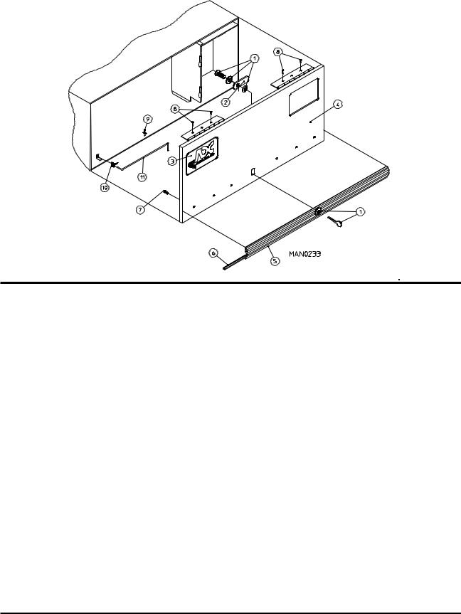
High Security Control Door Assembly |
|
ForALL Coin Models and ONLY OPL Models Mfd. prior to July 19, 1999 |
Illus. No. |
Part No. |
Qty. |
Description |
1 |
160015 |
1 |
High Security MK-100 Lock Assembly with Key |
|
|
|
(for Coin Models Only) |
|
160104 |
1 |
MK-100 Key ONLY |
|
160017 |
1 |
Special Dummy Lock ONLY |
|
|
|
(for Non-Coin Models Only) |
2 |
160016 |
1 |
Lock Cam ONLY |
3 |
881053 |
1 |
ADC Logo with Tape |
|
|
|
(for ALL Coin Models Only) |
|
881052 |
1 |
Metal ADC Logo with Tape |
|
|
|
(for ALL OPL Models Only) |
|
870011 |
1 |
Logo Double Tape Kit ONLY |
4* |
800023 |
1 |
High Security Control Door Assembly less Lock |
|
|
|
(includes illus. nos. 4 through 7) |
|
800140 |
1 |
High Security Stainless Steel Control Door Assembly Less Lock |
|
|
|
(includes illus. nos. 4 through 7) |
5 |
180200 |
1 |
Top Trim with Lock Hole |
6 |
117603 |
3 |
Trim Bumper Gasket (sold by the foot) |
7 |
150201 |
5 |
#10-32 x 1/4" Phillips Round Head Machine Screw |
8 |
150300 |
4 |
#10 x 1/2" Hex Washer TEK Screw |
9 |
102600 |
1 |
Control Door Support Rod Catch |
10 |
102601 |
1 |
Control Door Rod Retainer Clip |
11 |
102502 |
1 |
Control Door Support Rod |
*Specify color when ordering.
American Dryer Corporation |
88 Currant Road / Fall River, MA 02720-4781 |
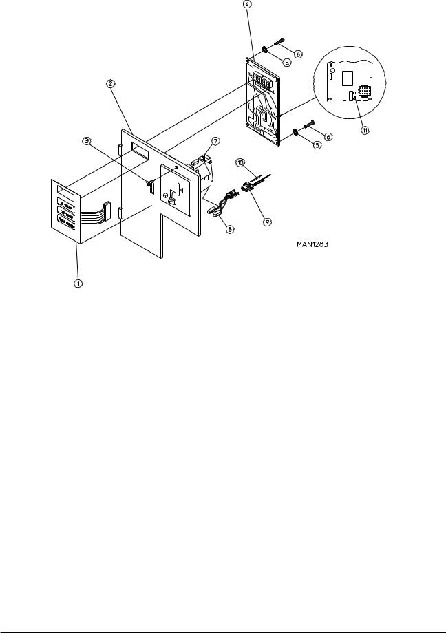
Phase 5 Coin Microprocessor Control Panel Assembly |
5 |
|||||||
|
|
|
|
|
|
|
|
|
|
|
|
|
|
|
|
|
|
|
|
|
|
|
|
|
|
|
|
|
|
|
|
|
|
|
|
|
|
|
|
|
|
|
|
|
|
|
|
|
|
|
|
|
|
|
|
|
|
|
|
|
|
|
|
|
|
|
|
|
|
|
|
|
|
|
|
|
|
|
|
|
|
|
|
|
|
|
|
|
|
Illus. No. |
Part No. |
Qty. |
Description |
1 |
112526 |
1 |
Coin Keyboard Label Assembly |
2 |
801213 |
1 |
Phase 5 Coin Control Panel Assembly |
|
|
|
(includes illus. nos. 1, 2, 4 through 6, and 11) |
|
801229 |
1 |
Phase 5 Coin Control Panel Assembly with Battery Option |
|
|
|
(includes illus. nos. 1, 2, 4 through 6, and 11) |
|
801259 |
1 |
Coin Control Panel ONLY |
|
801258 |
1 |
Coin Control Panel with Battery Bracket |
3 |
150309 |
1 |
#10-16 x 1/2" Hex Head TEK Crimptite Screw |
4 |
137213 |
1 |
Phase 5 Coin Microprocessor Controller (computer) ONLY |
|
824998 |
1 |
Phase 5 Battery Clip |
5 |
153010 |
2 |
#6 Star Washer |
6 |
150005 |
2 |
#6-32 x 1/4" Phillips Round Head Machine Screw |
7 |
--------- |
1 |
Microprocessor Coin Acceptor with Optical Switch |
|
|
|
(refer to Microprocessor Coin Acceptor Listing on page 52) |
8 |
137056 |
1* |
Optic Switch ONLY |
9 |
137023 |
1* |
Optic Switch Connector ONLY |
10 |
137021 |
3* |
Microprocessor Socket ONLY |
|
880772 |
1 |
Single Coin Optical Switch Harness |
|
824080 |
1 |
Dual Coin Optical Switch Harness |
|
122800 |
1 |
Microprocessor (female) Pin Extraction Tool |
11 |
136048 |
1 |
1/8-Amp (Slo Blo) Fuse |
*For Dual Coin Models double the quantity.
IMPORTANT: Check label on computer chip to verify correct part number for controller.
Telephone: (508) 678-9000 |
Fax: (508) 678-9447 |
6 |
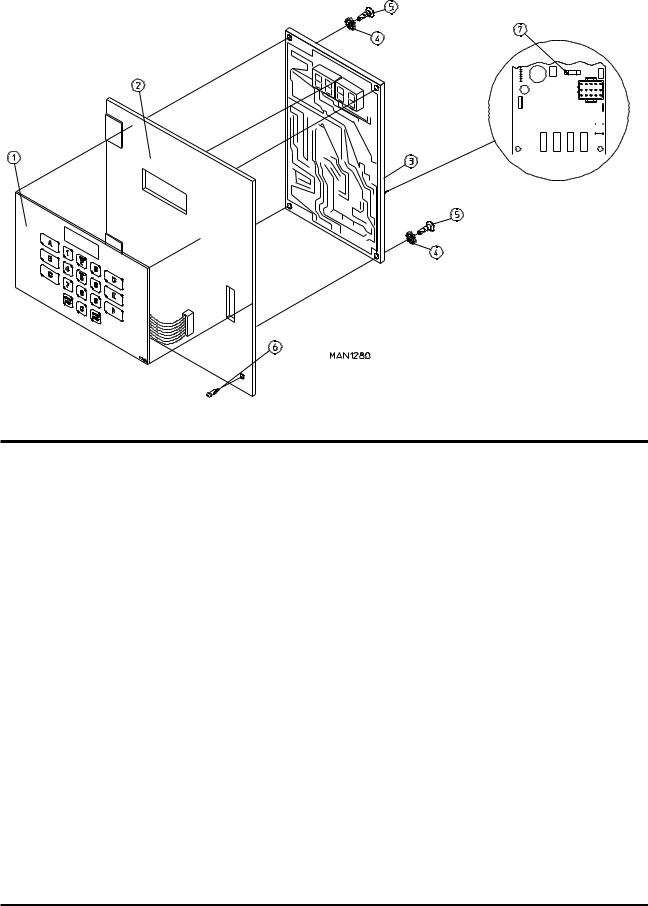
Phase 5 OPL Microprocessor Control Panel Assembly |
|||||||||
|
|
|
|
|
|
|
|
|
|
|
|
|
|
|
|
|
|
|
|
|
|
|
|
|
|
|
|
|
|
|
|
|
|
|
|
|
|
|
|
|
|
|
|
|
|
|
|
|
|
|
|
|
|
|
|
|
|
|
|
|
|
|
|
|
|
|
|
|
|
|
|
|
|
|
|
|
|
|
|
|
|
|
|
|
|
|
|
|
|
|
|
|
|
|
|
|
|
|
Illus. No. |
Part No. |
Qty. |
Description |
1 |
112535 |
1 |
OPL English Keyboard Label Assembly |
|
112276 |
1 |
OPL Stick-on Labels (English Only)...Not Illustrated |
|
112275 |
1 |
OPL Stick-on Labels |
|
|
|
(Spanish, Italian, and Hebrew)...Not Illustrated |
|
112277 |
1 |
3-Language OPL Stick-on Labels |
|
|
|
(English, Spanish, and Hebrew)...Not Illustrated |
|
112278 |
1 |
5-Language OPL Stick-on Labels |
|
|
|
(Italian, Dutch, French, German, and Chinese)...Not Illustrated |
2 |
801255 |
1 |
Phase 5 Microprocessor Control Panel ONLY |
|
801256 |
1 |
Phase 5 Microprocessor Control Panel ONLY with Battery Bracket |
|
801206 |
1 |
Phase 5 OPL Non-Reversing Microprocessor Control Panel Assembly |
|
|
|
Complete |
|
|
|
(includes illus. nos. 1 through 6 and 7) |
|
801207 |
1 |
Phase 5 OPL Reversing Microprocessor Control Panel Assembly Complete |
|
|
|
(includes illus. nos. 1 through 6 and 7) |
3 |
137222 |
1 |
Phase 5 OPL Non-Reversing Microprocessor Controller (computer) ONLY |
|
137231 |
1 |
Phase 5 OPL Reversing Microprocessor Controller (computer) ONLY |
|
824998 |
1 |
Phase 5 Battery Clip |
4 |
153010 |
2 |
#6 Star Washer |
5 |
150005 |
2 |
#6-32 x 3/4" Phillips Round Head Machine Screw |
6 |
150309 |
1 |
#10-16 x 1/2" Hex Head TEK Crimptite Screw |
7 |
136048 |
1 |
1/8-Amp (Slo Blo) Fuse |
IMPORTANT: Check label on computer chip to verify correct part number for controller (computer).
American Dryer Corporation |
88 Currant Road / Fall River, MA 02720-4781 |

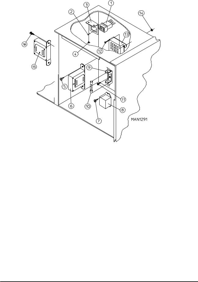
Phase 5 OPL and Coin Microprocessor Control Box Assembly |
7 |
|||
|
|
|
|
|
|
|
|
|
|
|
|
|
|
|
|
|
|
|
|
|
|
|
|
|
|
|
|
|
|
|
|
|
|
|
Illus. No. |
Part No. |
Qty. |
Description |
1 |
--------- |
1 |
Transformer - 24 VAC |
|
|
|
(refer to Transformer Usage Listings on page 53 and page 54) |
2 |
150300 |
2 |
#10 x 1/2" Hex Washer TEK Screw |
3 |
120715 |
1 |
30-Position Terminal Block |
4 |
150002 |
2 |
#6-32 x 1" Slotted Round Head Machine Screw |
5 |
151000 |
2 |
#6-32 Pal Nut |
6 |
136057 |
* |
1/2-Amp (Slo Blo) Fuse |
7 |
150301 |
* |
#8 x 7/16" Phillips Pan Head TEK Screw |
8 |
136008 |
* |
Fuse Block/Strip ONLY |
9 |
122641 |
1 |
15-Pin Microprocessor Connector |
10 |
122706 |
* |
Socket |
11 |
131931 |
1 |
Steam Valve Relay - 24 VAC |
|
|
|
(for Mechanical Steam Damper Models Only) |
12 |
150309 |
2 |
#10-16 x 1/2" Hex Head TEK Crimptite Screw |
13 |
137035 |
1 |
Motor Capacitor |
|
|
|
(for Mechanical Steam Damper Models Only) |
14 |
323583 |
1 |
Capacitor Bracket |
|
|
|
(for Mechanical Steam Damper Models Only) |
15 |
150300 |
2 |
#10 x 1/2" Hex Washer TEK Screw |
16 |
132002 |
1 |
Transformer |
|
|
|
(for Mechanical Steam Damper with 208 volt and higher models) |
17 |
150300 |
2 |
#10 x 1/2" Hex Washer TEK Screw |
*As required.
Telephone: (508) 678-9000 |
Fax: (508) 678-9447 |
8 |
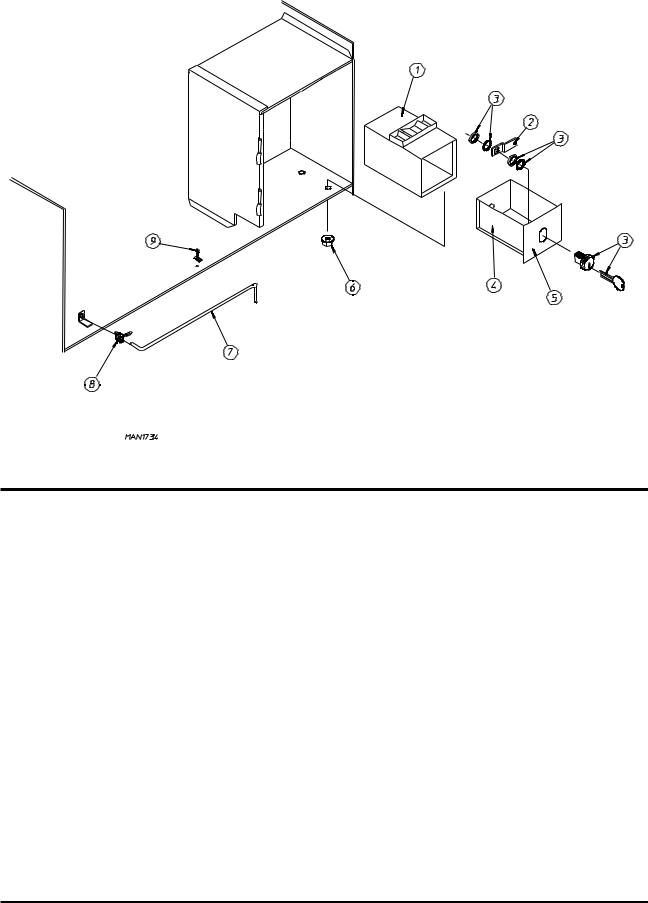
Coin Vault Assembly |
Illus. No. |
Part No. |
Qty. |
Description |
1 |
802112 |
1 |
Microprocessor Coin Vault Assembly Complete |
|
|
|
(includes illus. nos. 1 through 6) |
|
802117 |
1 |
Microprocessor Coin Vault ONLY |
|
802110 |
1 |
Non-Microprocessor Coin Vault Assembly Complete |
|
|
|
(includes illus. nos. 1 through 6) |
|
802115 |
1 |
Non-Microprocessor Coin Vault ONLY |
2 |
160006 |
1 |
Cam for 1/4 Turn Lock ONLY |
3 |
875061 |
1 |
1/4 Turn Lock with Key and Cam |
|
160105* |
1 |
1/4 Turn Mer-Pel Key ONLY |
4 |
802020 |
1 |
1/4 Turn Coin Box Assembly |
|
|
|
(includes illus. nos. 2 through 5) |
|
802019 |
1 |
1/4 Turn Coin Box ONLY without Face Plate |
|
125915 |
1 |
High Security (Greenwald) Coin Box ONLY with Key |
5 |
802018 |
1 |
1/4 Turn Coin Box Face Plate Assembly |
|
|
|
(includes illus. nos. 2 through 5) |
6 |
152014 |
4 |
1/4-20 Free Spin Wash Nut |
7 |
102502 |
1 |
Control Door Support Rod |
8 |
102601 |
1 |
Control Door Rod Retainer Clip |
9 |
102600 |
1 |
Control Door Rod Catch |
*Specify key number when ordering.
American Dryer Corporation |
88 Currant Road / Fall River, MA 02720-4781 |
Dual Timer “Tap Touch” Controls |
9 |
For Models Mfd. as of November 1, 2000 |
|
Illus. No. |
Part No. |
Qty. |
Description |
1 |
824298 |
1 |
15 Minute Timer - 24 VAC |
2 |
824299 |
1 |
60 Minute Timer - 24 VAC |
3 |
824175 |
1 |
Red Pilot Light - 24 VAC |
4 |
122301 |
1 |
“Tap Touch” Switch |
5 |
131932 |
3 |
Relay SPST 24v |
6 |
120730 |
1 |
30-Position Terminal Block |
7 |
151000 |
6 |
#6-32 Pal Nut |
8 |
882903 |
1 |
Dual Timer Panel Complete |
|
|
|
(includes illus. nos. 1 through 15) |
|
850392 |
- |
Dual Timer Panel ONLY |
9 |
153010 |
2 |
#6 Star Washer |
10 |
152000 |
3 |
#6-32 Hex Nut |
11 |
150207 |
2 |
#10-24 x 1/2” Phillips Pan Head Machine Screw |
12 |
150110 |
4 |
#8-32 x 1/4” Phillips Round Head Machine Screw |
13 |
112563 |
1 |
Dual Timer Panel Overlay |
14 |
124104 |
1 |
Pure Touch Knob with Red Pointer |
15 |
124105 |
1 |
Pure Touch Knob with Blue Pointer |
Telephone: (508) 678-9000 |
Fax: (508) 678-9447 |
10 |
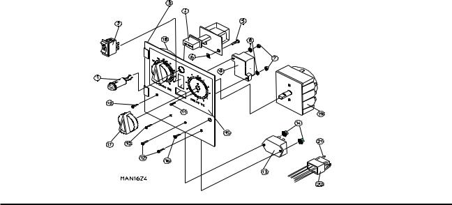
Dual Timer Control Panel Assembly |
|
For Models Mfd. prior to November 1, 2000 |
Illus. No. |
Part No. |
Qty. |
Description |
1 |
123005 |
1 |
Red Indicator Light - 24 VAC |
2 |
122400 |
1 |
Rocker Heat Selector Switch |
3 |
824015 |
1 |
Dual Timer Control Panel Assembly Complete - 24 VAC |
|
|
|
(includes illus. nos. 1 through 21) |
|
800051 |
1 |
Dual Timer Control Panel ONLY |
4 |
131917 |
1 |
Push-to-Start Relay - 24 VAC |
5 |
150207 |
2 |
#10-24 x 1/2" Round Head Machine Screw |
6 |
154001 |
2 |
#10-24 Speed Nut |
7 |
152000 |
2 |
#6-32 Hex Nut |
8 |
153010 |
2 |
#6 Star Washer |
9 |
120713 |
1 |
18-Position Terminal Block |
10 |
150002 |
2 |
#6-32 x 1" Round Head Machine Screw |
11 |
150110 |
4 |
#8-32 x 1/4" Phillips Machine Screw |
12 |
150001 |
2 |
#6-32 x 1/2" Round Head Machine Screw |
13 |
131931 |
1 |
Dual Timer Relay - 24 VAC |
14 |
151000 |
2 |
#6-32 Pal Nut |
15 |
112050 |
1 |
Dual Timer Label ONLY |
16 |
150309 |
1 |
#10-16 x 1/2" Hex Head TEK Crimptite Screw |
|
|
|
(for models mfd. as of March 1, 1994) |
|
160005 |
1 |
2-Piece Spring Turn Latch |
|
|
|
(for models mfd. as of March 1, 1994) |
17 |
124103 |
2 |
Arrow Timer - 24 VAC |
18 |
124025 |
1 |
60-Minute Timer - 24 VAC |
19 |
124030 |
1 |
15-Minute Timer - 24 VAC |
20 |
122602 |
1 |
9-Pin Connector ONLY |
21 |
122700 |
8 |
Pin Terminal ONLY |
--- |
122801 |
1 |
Pin/Socket Extraction Tool |
American Dryer Corporation |
88 Currant Road / Fall River, MA 02720-4781 |
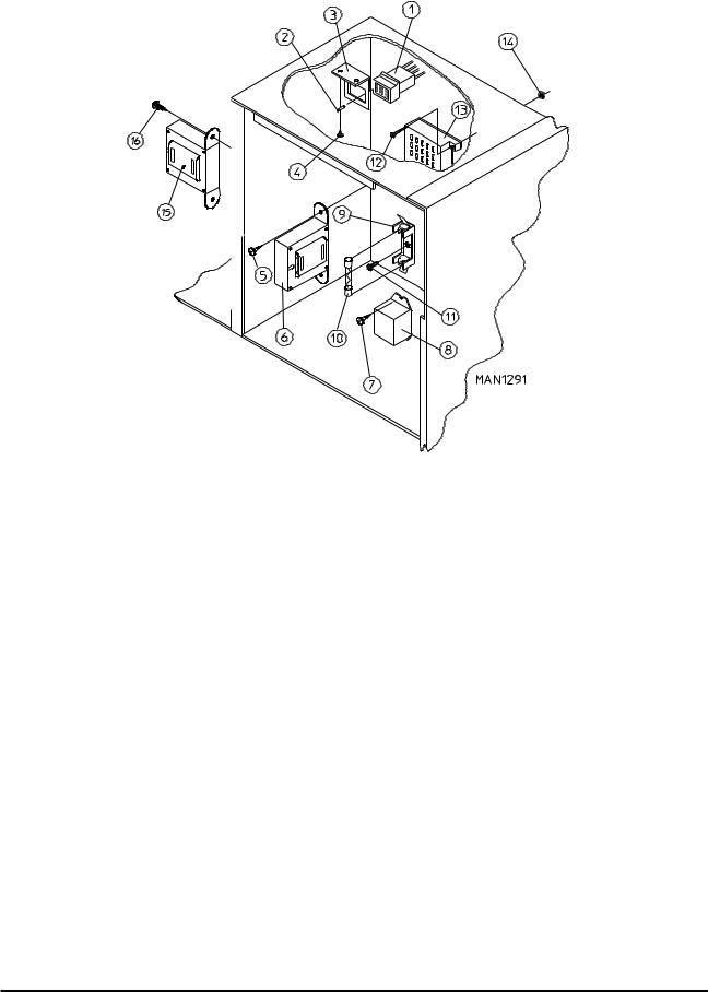
Dual Timer Control Box Assembly |
11 |
|||||
|
|
|
|
|
|
|
|
|
|
|
|
|
|
|
|
|
|
|
|
|
|
|
|
|
|
|
|
|
|
|
|
|
|
|
|
|
|
|
|
|
|
|
|
|
|
|
|
|
|
|
|
|
|
|
|
|
|
|
|
|
|
|
|
|
|
|
|
|
|
Illus. No. |
Part No. |
Qty. |
Description |
1 |
122603 |
1 |
9-Pin Socket Connector |
2 |
122701 |
9 |
Socket Terminal ONLY |
|
122801 |
1 |
Pin/Socket Extraction Tool |
3 |
315010 |
1 |
9-Pin Connector Bracket |
4 |
150300 |
2 |
#10 x 1/2" Hex Washer TEK Screw |
5 |
150300 |
2 |
#10 x 1/2" Hex Washer TEK Screw |
6 |
--------- |
1 |
Transformer - 24 VAC |
|
|
|
(refer to Transformer Usage Listings on page 53 and page 54) |
7 |
150309 |
2 |
#10-16 x 1/2" Hex Head TEK Crimptite Screw |
8 |
131931 |
1 |
Steam Valve Relay - 24 VAC |
|
|
|
(for Mechanical Steam Damper Models Only) |
9 |
136008 |
* |
Fuse Block/Strip ONLY |
10** |
136057 |
* |
1/2-Amp (Slo Blo) Fuse |
11 |
150301 |
* |
#8 x 7/16" Phillips Pan Head TEK Screw |
12 |
150002 |
2 |
#6-32 x 1" Slotted Round Head Machine Screw |
13 |
120715 |
1 |
30-Position Terminal Block |
14 |
151000 |
2 |
#6-32 Pal Nut |
15 |
132002 |
1 |
Transformer |
|
|
|
(for Mechanical Steam Damper with 208 volt and higher models) |
16 |
150300 |
2 |
#10 x 1/2" Hex Washer TEK Screw |
*As required.
**Check fusing on dryer for verification.
Telephone: (508) 678-9000 |
Fax: (508) 678-9447 |
12 |
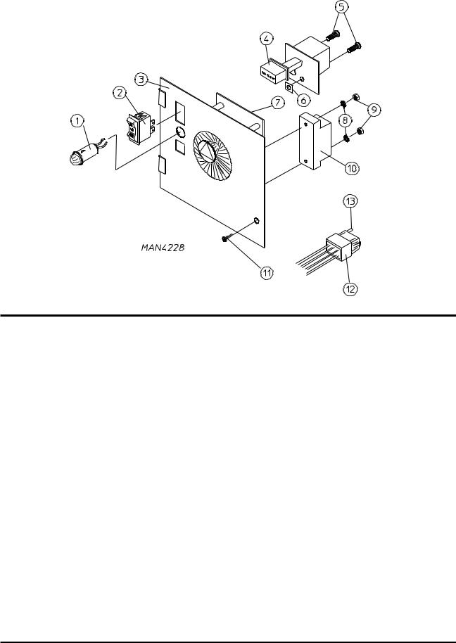
Non-Microprocessor Coin Meter Control Panel Assembly |
Illus. No. |
Part No. |
Qty. |
Description |
1 |
123005 |
1 |
Red Indicator Light - 24 VAC |
2 |
122400 |
1 |
Rocker Heat Selector Switch |
3 |
824020 |
1 |
Coin Meter Control Panel Assembly Complete - 24 VAC |
|
|
|
(includes illus. nos. 1 through 6 and 8 through 12) |
|
800054 |
1 |
Coin Meter Control Panel ONLY |
4 |
131917 |
1 |
Push-to-Start Relay - 24 VAC |
5 |
150207 |
2 |
#10-24 x 1/2" Round Head Machine Screw |
6 |
154001 |
2 |
#10-24 Speed Nut |
7* |
125601 |
1 |
25¢ Coin Meter - 24 VAC (specify timing) |
8 |
153010 |
2 |
#6 Star Washer |
|
|
|
(for models mfd. as of December 11, 1998) |
9 |
152016 |
2 |
#4-40 Hex Nut |
|
|
|
(for models mfd. as of December 11, 1998) |
|
150303 |
2 |
#4 x 3/4" Pan Head "A" Screw...Not Illustrated |
|
|
|
(for models mfd. prior to December 11, 1998) |
10 |
120712 |
1 |
12-Position Terminal Block |
11 |
150309 |
1 |
#10-16 x 1/2" Hex Head TEK Crimptite Screw |
|
160005 |
1 |
2-Piece Spring Turn Latch |
|
|
|
(used on models mfd. prior to March 1, 1994) |
12 |
122602 |
1 |
9-Pin Connector ONLY |
13 |
122700 |
9 |
Pin Terminal ONLY |
-- |
122801 |
1 |
Pin/Socket Extraction Tool |
*Consult factory for coin meters not listed.
American Dryer Corporation |
88 Currant Road / Fall River, MA 02720-4781 |
Non-Microprocessor Coin Meter Control Box Assembly |
13 |
|||||
|
|
|
|
|
|
|
|
|
|
|
|
|
|
|
|
|
|
|
|
|
|
|
|
|
|
|
|
|
|
|
|
|
|
|
|
|
|
|
|
|
|
|
|
|
|
|
|
|
|
|
|
|
|
|
|
Illus. No. |
Part No. |
Qty. |
Description |
1 |
122603 |
1 |
9-Pin Socket Connector |
2 |
122701 |
9 |
Socket Terminal ONLY |
|
122801 |
1 |
Pin/Socket Extraction Tool |
3 |
315010 |
1 |
9-Pin Connector Bracket |
4 |
150300 |
2 |
#10 x 1/2" Hex Washer TEK Screw |
5 |
150300 |
2 |
#10 x 1/2" Hex Washer TEK Screw |
6 |
--------- |
1 |
Transformer - 24 VAC |
|
|
|
(refer to Transformer Usage Listings on page 53 and page 54) |
7 |
150309 |
2 |
#10-16 x 1/2" Hex Head TEK Crimptite Screw |
8 |
131931 |
1 |
Steam Valve Relay - 24 VAC |
|
|
|
(for Mechanical Steam Damper Models Only) |
9 |
136008 |
* |
Fuse Block/Strip ONLY |
10** |
136057 |
* |
1/2 Amp (Slo Blo) Fuse |
11 |
150301 |
* |
#8 x 7/16" Phillips Pan Head TEK Screw |
12 |
150002 |
2 |
#6-32 x 1" Slotted Round Head Machine Screw |
13 |
120715 |
1 |
30-Position Terminal Block |
14 |
151000 |
2 |
#6-32 Pal Nut |
15 |
132002 |
1 |
Transformer |
|
|
|
(for Mechanical Steam Damper with 208 volt and higher models) |
16 |
150300 |
2 |
#10 x 1/2" Hex Washer TEK Screw |
*As required.
**Check fusing on dryer for verification.
Telephone: (508) 678-9000 |
Fax: (508) 678-9447 |

14 |
Slide Meter Case Assembly |
||
|
|
|
|
|
|
|
|
|
|
|
|
MAN1625
|
|
|
|
|
|
Illus. No. |
Part No. |
Qty. |
Description |
|
|
|
|
||||
1* |
160199 |
1 |
Key ONLY for Slide Meter Lock |
|
|
2 |
160099 |
1 |
Lock/Key/Cam and Hardware |
|
|
3 |
125908 |
1 |
Slide Meter Accumulator - 24 VAC |
|
|
4 |
152014 |
4 |
1/4-20 Free Spin Wash Nut |
|
|
5 |
125900 |
1 |
Slide Meter Case ONLY with Door Less Locks |
|
|
6 |
154203 |
6 |
1/4" Drive Rivet |
|
|
7 |
801700 |
1 |
Slide Meter Extension ONLY with Mirror |
|
|
|
|
|
(includes illus. nos. 7 and 8) |
|
|
8 |
315404 |
1 |
Stainless Steel Mirror ONLY |
|
|
9 |
--------- |
1 |
Typical Slide Meter Coin Chute (not available from ADC) |
|
|
10 |
--------- |
1 |
Typical Slide Meter Coin Box (not available from ADC) |
|
|
11 |
801701 |
1 |
Slide Meter Case Mounting Plate |
|
|
12 |
102502 |
1 |
Control Door Support Rod |
|
|
13 |
102601 |
1 |
Control Door Rod Retainer Clip |
|
|
14 |
102600 |
1 |
Control Door Support Rod Catch |
|
|
15 |
122400 |
1 |
Rocker Heat Selector Switch |
|
|
16 |
123005 |
1 |
Red Indicator Light - 24 VAC |
|
|
17 |
131917 |
1 |
Push to-Start Relay - 24 VAC |
|
|
*Specify key number when ordering.
American Dryer Corporation |
88 Currant Road / Fall River, MA 02720-4781 |

|
Slide Meter Control Box |
15 |
|
|
|
|
|
|
|
|
|
|
|
|
|
|
|
|
|
|
|
|
|
|
|
|
|
|
|
|
|
|
|
|
|
|
|
|
|
Illus. No. |
Part No. |
Qty. |
Description |
1 |
132451 |
1 |
2-Pole Contactor - 24 VAC |
2 |
150299 |
2 |
#10 x 1" Hex Head Screw |
3 |
824828 |
1 |
RC Network with Connectors |
4 |
150300 |
2 |
#10 x 1/2" Hex Washer TEK Screw |
5 |
--------- |
1 |
24 VAC Control Voltage Transformer |
|
|
|
(refer to Transformer Usage Listings on page 53 and page 54) |
6 |
136057 |
* |
1/2 Amp (Slo-Blo) Fuse |
7 |
150301 |
* |
#8 x 7/16" Phillips Pan Head TEK Screw |
8 |
136008 |
* |
Fuse Block/Strip ONLY |
9 |
150002 |
2 |
#6-32 x 1" Round Head Machine Screw |
10 |
120715 |
1 |
30-Position Terminal Block |
11 |
151000 |
2 |
#6-32 Pal Nut |
-- |
322809 |
1 |
Back Electrical Box Cover...Not Illustrated |
-- |
150301 |
4 |
#8-18 x 7/16" Phillips Pan Head TEK Screw...Not Illustrated |
*As required.
Telephone: (508) 678-9000 |
Fax: (508) 678-9447 |
16 |
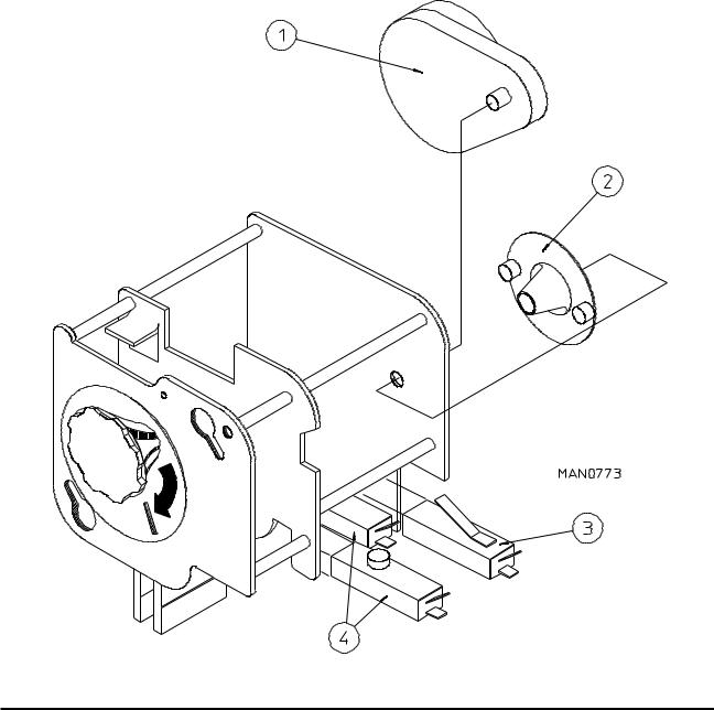
Coin Meter Replacement Parts |
Illus. No. |
Part No. |
Qty. |
Description |
1 |
125541 |
1 |
1/60 RPM - 60 Hz Meter Motor - 24 VAC |
|
125540 |
1 |
1/30 RPM - 50 Hz Meter Motor - 24 VAC |
2 |
125500 |
1 |
2-Point Cam |
|
125501 |
1 |
3-Point Cam |
|
125502 |
1 |
4-Point Cam |
|
125503 |
1 |
5-Point Cam |
|
125504 |
1 |
6-Point Cam |
|
125506 |
1 |
8-Point Cam |
|
125507 |
1 |
9-Point Cam |
|
125508 |
1 |
10-Point Cam |
|
125510 |
1 |
12-Point Cam |
3 |
125515 |
1 |
Meter Switch "B" with Arm |
4 |
125516 |
2 |
Meter Switch "A" or "C" |
American Dryer Corporation |
88 Currant Road / Fall River, MA 02720-4781 |
 Loading...