


 Loading...
AD-75V / AD-758V
Parts Manual
Phase 7 / Dual Timer / OPL with Fire Suppression System Options
American Dryer Corporation
88 Currant Road
Fall River, MA 02720-4781
Telephone: (508) 678-9000 / Fax: (508) 678-9447
E-mail: techsupport@amdry.com
www.amdry.com
ADC Part No. 450229-3

Retain This Manual In A Safe Place For Future Reference
American Dryer Corporation products embody advanced concepts in engineering, design, and safety. If this product is properly maintained, it will provide many years of safe, efficient, and trouble free operation.
ONLY qualified technicians should service this equipment.
OBSERVE ALL SAFETY PRECAUTIONS displayed on the equipment or specified in the installation manual included with the dryer.
The following “FOR YOUR SAFETY” caution must be posted near the dryer in a prominent location.
FOR YOUR SAFETY
Do not store or use gasoline or other flammable vapors and liquids in the vicinity of this or any other appliance.
POUR VOTRE SÉCURITÉ
Ne pas entreposer ni utiliser d’essence ni d’autres vapeurs ou liquides inflammables à proximité de cet appareil ou de tout autre appareil.
We have tried to make this manual as complete as possible and hope you will find it useful. ADC reserves the right to make changes from time to time, without notice or obligation, in prices, specifications, colors, and material, and to change or discontinue models.
Important
For your convenience, log the following information:
DATE OF PURCHASE ____________________________________________________ MODEL NO. ______________
RESELLER’S NAME _________________________________________________________________________________
Serial Number(s) _____________________________________________________________________________________
____________________________________________________________________________________________________
____________________________________________________________________________________________________
Replacement parts can be obtained from your reseller or the ADC factory. When ordering replacement parts from the factory, you can FAX your order to ADC at (508) 678-9447 or telephone your order directly to the ADC Parts Department at (508) 678-9000. Please specify the dryer model number and serial number in addition to the description and part number, so that your order is processed accurately and promptly.
The illustrations on the following pages may not depict your particular dryer exactly. The illustrations are a composite of the various dryer models. Be sure to check the descriptions of the parts thoroughly before ordering.
“IMPORTANT NOTE TO PURCHASER”
Information must be obtained from your local gas supplier on the instructions to be followed if the user smells gas. These instructions must be posted in a prominent location near the dryer.
Table of Contents |
|
Phase 7 OPL Control Door Assembly ........................................................................................................................ |
4 |
Coin Control Door Assembly ...................................................................................................................................... |
5 |
Dual Timer OPL Control Door Assembly .................................................................................................................... |
6 |
Phase 7 OPL Microprocessor Control Panel Assembly ............................................................................................. |
7 |
Phase 7 Coin Microprocessor Control Panel Assembly ............................................................................................. |
8 |
Dual Timer “Tap Touch” Controls................................................................................................................................ |
9 |
Phase 7 Microprocessor Control Box Assembly ...................................................................................................... |
10 |
Coin Vault Assembly ................................................................................................................................................. |
11 |
Dual Timer Control Box Assembly ............................................................................................................................ |
12 |
Front Panel Assembly .............................................................................................................................................. |
13 |
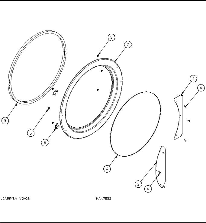
37-1/4” Main Door Assembly for Models Mfd. as of September 11, 2006 ................................................................ |
14 |
25-1/2” Main Door Assembly for Models Mfd. prior to September 11, 2006 ............................................................. |
15 |
Main Door Switch Assembly for Models Mfd. as of September 11, 2006 ................................................................. |
16 |
Main Door Switch Assembly for Models Mfd. prior to September 11, 2006 .............................................................. |
17 |
Tumbler / Support Assemblies ................................................................................................................................. |
18 |
Lint Drawer / Lint Drawer Switch Assembly .............................................................................................................. |
19 |
Idler Bearing Assembly............................................................................................................................................. |
20 |
Tumbler Bearing Assembly ...................................................................................................................................... |
21 |
Non-Reversing Motor Mount Assembly .................................................................................................................... |
22 |
Reversing Motor Mount Assembly ............................................................................................................................ |
24 |
Sensor Bracket Assemblies ..................................................................................................................................... |
26 |
Direct Spark Ignition Burner Assembly ..................................................................................................................... |
28 |
Direct Spark Ignition Burner CE Assembly ............................................................................................................... |
30 |
Electric Oven Assembly............................................................................................................................................ |
32 |
Sail Switch Assembly ............................................................................................................................................... |
34 |
Single-Phase (1ø) Microprocessor Rear Electric Relay Panel Assembly ................................................................. |
35 |
208-240V 3-Phase (3ø) Microprocessor Rear Electric Relay Panel Assembly ........................................................ |
36 |
460-480V Microprocessor Rear Electric Relay Panel Assembly .............................................................................. |
37 |
208-240V Microprocessor Reversing Rear Electric Relay Panel Assembly ............................................................. |
38 |
460-480V Microprocessor Reversing Rear Electric Relay Panel Assembly ............................................................. |
39 |
Single-Phase (1ø) Dual Timer Rear Electric Relay Panel Assembly ........................................................................ |
40 |
460-480V Dual Timer Rear Electric Relay Panel Assembly ..................................................................................... |
42 |
208-240V Dual Timer Reversing Rear Electric Relay Panel Assembly .................................................................... |
43 |
Air-Operated Steam Damper Assembly ................................................................................................................... |
44 |
Fire Suppression System Assemblies ...................................................................................................................... |
46 |
Outer Top / Back Guard Assemblies for Models Mfd. as of January 5, 2003 ........................................................... |
47 |
Outer Top / Back Guard Assemblies for Models Mfd. prior to January 5, 2003 ........................................................ |
48 |
Microprocessor Electric Oven Component Application Chart ................................................................................... |
49 |
Dual Timer Electric Oven Component Application Chart .......................................................................................... |
50 |
Additional Parts Available ......................................................................................................................................... |
51 |
Phase 7 OPL Control Door Assembly
|
|
|
|
|
|
|
|
|
|
|
|
|
|
|
|
|
|
|
|
|
|
|
|
|
|
|
|
|
|
|
|
|
|
|
|
|
|
|
|
|
|
|
|
|
|
|
|
|
|
|
|
|
|
|
|
|
|
|
|
|
|
|
|
|
|
|
|
|
|
|
|
Illus. No. |
Part No. |
Qty. |
Description |
|
|
|
||
1 |
883758 |
1 |
White OPL Control Door |
|
|
|
||
|
|
|
|
(includes illus. nos. 1 and 3) |
|
|
|
|
|
|
883756 |
1 |
Ivory OPL Control Door |
|
|
|
|
|
|
|
|
(includes illus. nos. 1 and 3) |
|
|
|
|
|
|
883759 |
1 |
Coral Blue OPL Control Door |
|
|
|
|
|
|
|
|
(includes illus. nos. 1 and 3) |
|
|
|
|
2 |
150321 |
2 |
#10-32 x 1/2” Phillips Machine Screw |
|
|
|
||
3 |
117604 |
4 |
Noise Suppression Tape (sold by the foot) |
|
|
|
||
4 |
150317 |
2 |
#10-16 x 3/4” TORX PLUS® BTN, Type 1 |
|
|
|
||
5 |
102503 |
1 |
Control Door Support Rod |
|
|
|
||
6 |
154011 |
2 |
#10-32 Multi-Thread U-Nut |
|
|
|
||
7 |
102603 |
1 |
Control Door Rod Support Catch |
|
|
|
||
8 |
102601 |
1 |
Control Door Rod Retainer Clip |
|
|
|
||
|
|
|
|
|
|
|
|
|
4 |
|
|
|
American Dryer Corporation |
450229-3 |
|||
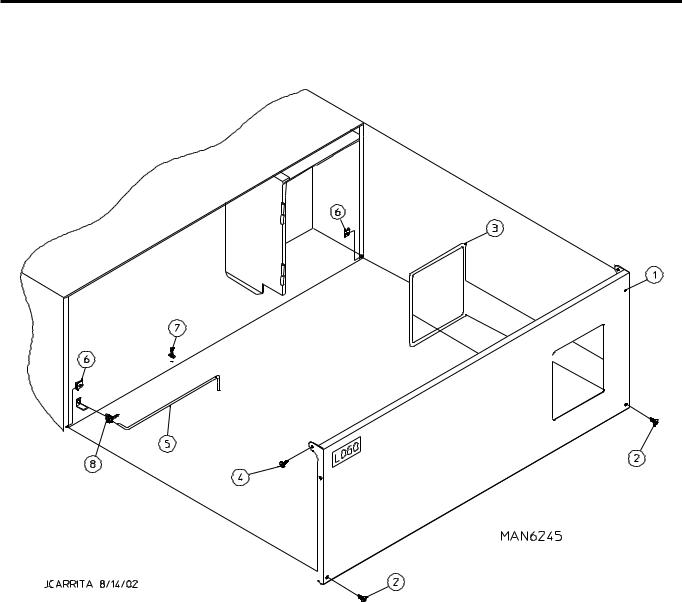
Coin Control Door Assembly
Illus. No. |
Part No. |
Qty. |
Description |
1 |
160015 |
1 |
High Security MK-100 Lock Assembly with Key |
|
160104 |
1 |
MK-100 Key ONLY |
2 |
160032 |
1 |
Lock Cam ONLY |
3 |
881053 |
1 |
ADC Logo with Tape |
4 |
817246* |
1 |
Control Door Assembly with Black Trim |
|
|
|
(includes illus. nos. 4 through 7) |
5 |
817164 |
1 |
Black Trim |
6 |
117604 |
6 |
Neoprene Sponge Tape (sold by the foot) |
7 |
152014 |
4 |
1/4-20 Free Spin Wash Nut |
8 |
150317 |
2 |
#10-16 x 3/4” TORX PLUS® BTN, Type 1 |
|
150318 |
1 |
TORX PLUS® Bit |
9 |
102603 |
1 |
Control Door Support Rod Catch |
10 |
102601 |
1 |
Control Door Rod Retainer Clip |
11 |
102503 |
1 |
Control Door Support Rod |
* Specify color when ordering.
450229-3 |
www.amdry.com |
5 |
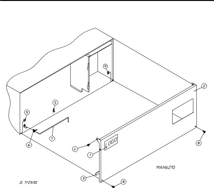
Dual Timer OPL Control Door Assembly
|
|
|
|
|
|
|
|
|
|
|
|
|
|
|
|
|
|
|
|
|
|
|
|
|
|
|
|
|
|
|
|
|
|
|
|
|
|
|
|
|
|
|
|
|
|
|
|
1 |
881053 |
1 |
ADC Logo with Tape |
|
|
||
|
|
870011 |
1 |
Double Sided Tape Kit |
|
|
|
2 |
883616 |
1 |
White Control Door Assembly |
|
|
||
|
|
|
|
(includes illus. nos. 2 and 3) |
|
|
|
|
|
883618 |
1 |
Ivory Control Door Assembly |
|
|
|
|
|
|
|
(includes illus. nos. 2 and 3) |
|
|
|
|
|
883617 |
1 |
Coral Blue Control Door Assembly |
|
|
|
|
|
|
|
(includes illus. nos. 2 and 3) |
|
|
|
3 |
117604 |
3 |
Noise Suppression Tape (sold by the foot) |
|
|
||
4 |
150317 |
2 |
#10-16 x 3/4” TORX PLUS® BTN, Type 1 |
|
|
||
5 |
102603 |
1 |
Control Door Rod Support Catch |
|
|
||
6 |
102601 |
1 |
Control Door Rod Retainer Clip |
|
|
||
7 |
102503 |
1 |
Control Door Support Rod |
|
|
||
8 |
150321 |
2 |
#10-32 x 1/2” Phillips Machine Screw |
|
|
||
9 |
154011 |
2 |
#10-32 Multi-Thread U-Nut |
|
|
||
|
|
|
|
|
|
|
|
6 |
|
|
|
American Dryer Corporation |
450229-3 |
||
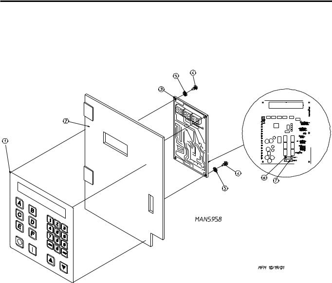
Phase 7 OPL Microprocessor Control Panel Assembly
|
|
|
|
|
|
|
|
|
|
|
|
|
|
|
|
|
|
|
|
|
|
|
|
|
|
|
|
|
|
|
|
|
|
|
|
|
|
|
|
|
|
|
|
|
|
|
|
|
|
|
|
|
|
|
|
|
|
|
|
|
|
|
|
|
|
|
|
|
|
|
|
|
|
|
|
|
|
|
|
|
|
|
|
|
|
|
|
|
|
|
|
|
|
|
|
|
|
|
|
|
|
|
|
|
|
|
|
|
|
|
|
|
|
|
|
|
|
|
|
|
|
|
|
|
|
|
|
|
|
|
|
|
|
|
|
|
|
|
|
|
|
|
|
|
|
|
|
|
|
|
|
|
|
|
|
|
|
|
|
|
|
|
|
|
|
|
|
|
|
|
|
|
|
|
|
|
|
|
|
|
|
|
|
|
|
|
|
|
|
|
|
|
|
|
|
|
|
|
|
|
|
|
|
|
|
|
|
|
|
|
|
|
|
|
|
|
|
|
|
|
|
|
|
|
|
|
|
|
|
|
|
|
|
|
|
|
|
|
|
|
|
|
|
|
|
|
|
|
|
|
|
|
|
|
|
|
|
|
|
|
Illus. No. |
Part No. |
Qty. |
Description |
|
|
|
|
|||||||||||
|
1 |
|
112577 |
1 |
Phase 7 OPL Keypad |
|
|
|
|
||||||||||
|
2 |
|
850984 |
1 |
Phase 7 OPL Microprocessor Controller (computer) Panel ONLY |
|
|
|
|
||||||||||
|
3 |
|
887003 |
1 |
Phase 7.2.2 Board with Fire Suppression System and H2O (pressure) Switch |
|
|
|
|
||||||||||
|
|
|
887000 |
|
Phase 7.2.2 Board with Fire Suppression System and no H2O (pressure) Switch |
|
|
|
|
||||||||||
|
|
|
887023 |
|
Phase 7.2.2 Board “Dutch” and “Polish” with Fire Suppression System |
|
|
|
|
||||||||||
|
|
|
887024 |
|
and H2O Pressure Switch |
|
|
|
|
||||||||||
|
|
|
|
Phase 7.2.2 Board without Fire Suppression System |
|
|
|
|
|||||||||||
|
4 |
|
150005 |
2 |
#6-32 x 3/4” Phillips Round Head Machine Screw |
|
|
|
|
||||||||||
|
5 |
|
153010 |
2 |
#6 Star Washer |
|
|
|
|
||||||||||
|
6 |
|
136097 |
1 |
500 mA Fuse |
|
|
|
|
||||||||||
|
7 |
|
136016 |
1 |
5-Amp Fuse |
|
|
|
|
||||||||||
|
|
|
|
|
|
|
|
|
|
|
|
|
|
|
|
|
|
|
|
|
450229-3 |
|
|
www.amdry.com |
7 |
|
|||||||||||||
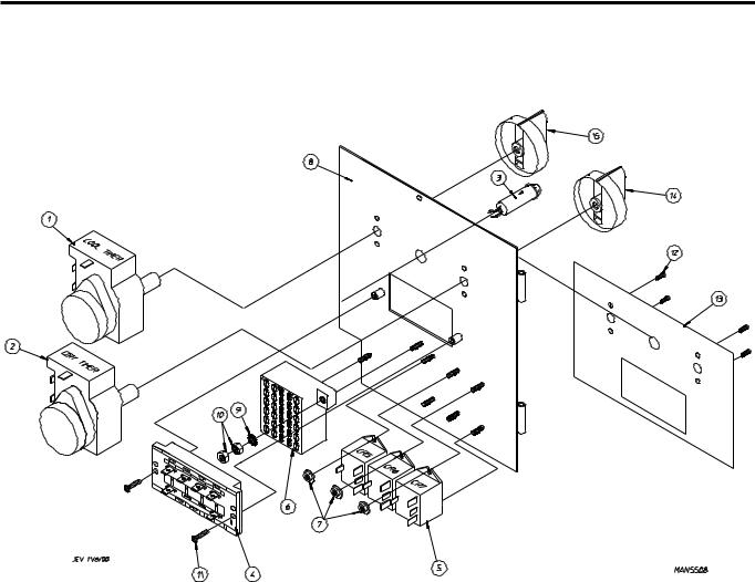
Phase 7 Coin Microprocessor Control Panel Assembly
Illus. No. |
Part No. |
Qty. |
Description |
|
1 |
137250 |
1 |
Phase 7 Coin Ribbon Cable |
|
2 |
137270 |
1 |
16” x 1” Large Character Display |
|
3 |
887007 |
1 |
Phase 7 Coin Board (for models without Fire Suppression System) |
|
|
887009 |
1 |
Phase 7 Coin Board (for models with Fire Suppression System) |
|
4 |
887012 |
2 |
Phase 7 Coin Board (for models mfd. with Fire Suppression System and H2O switch) |
|
112575 |
1 |
Phase 7 Keypad |
|
|
5 |
153010 |
4 |
#6 Internal and External Star Washers |
|
6 |
150005 |
4 |
#6-32 x 1/4” Phillips Round Head Machine Screw |
|
7 |
152102 |
4 |
M3 Metric Hex Nut |
|
8 |
823145 |
1 |
Phase 7 Coin Control Panel ONLY |
|
9 |
818232 |
1 |
Phase 7 25¢ Coin Acceptor Assembly |
|
|
830159 |
|
Phase 7 Programmable Euro Coin Acceptor Assembly |
|
|
830136 |
|
Phase 7 Programmable Shekel Coin Acceptor Assembly |
|
|
830006 |
|
Phase 7 Programmable NZD / AUD / HKD Coin Acceptor Assembly |
|
10 |
122633 |
1 |
3-Pin Connector |
|
|
|
|
|
|
8 |
|
|
American Dryer Corporation |
450229-3 |
Dual Timer “Tap Touch” Controls
|
|
|
|
|
|
|
|
|
|
|
|
|
|
|
Illus. No. |
Part No. |
Qty. |
Description |
|
|
|
1 |
824298 |
1 |
15 Minute Timer – 24 VAC |
|
|
|
2 |
824299 |
1 |
60 Minute Timer – 24 VAC |
|
|
|
3 |
824175 |
1 |
Red Pilot Light – 24 VAC |
|
|
|
4 |
122301 |
1 |
“Tap Touch” Switch |
|
|
|
5 |
131932 |
3 |
Relay SPST 24v |
|
|
|
6 |
120730 |
1 |
30-Position Terminal Block |
|
|
|
7 |
151000 |
6 |
#6-32 Pal Nut |
|
|
|
8 |
882903 |
1 |
Dual Timer Panel Complete |
|
|
|
|
|
|
(includes illus. nos. 1 through 15) |
|
|
|
|
850392 |
– |
Dual Timer Panel ONLY |
|
|
|
9 |
153010 |
2 |
#6 Star Washer |
|
|
|
10 |
152000 |
3 |
#6-32 Hex Nut |
|
|
|
11 |
150207 |
2 |
#10-24 x 1/2” Phillips Pan Head Machine Screw |
|
|
|
12 |
150110 |
4 |
#8-32 x 1/4” Phillips Round Head Machine Screw |
|
|
|
13 |
112563 |
1 |
Dual Timer Panel Overlay |
|
|
|
14 |
124104 |
1 |
Pure Touch Knob with Red Pointer |
|
|
|
15 |
124105 |
1 |
Pure Touch Knob with Blue Pointer |
|
|
|
|
|
|
|
|
|
|
450229-3 |
|
|
www.amdry.com |
9 |
|

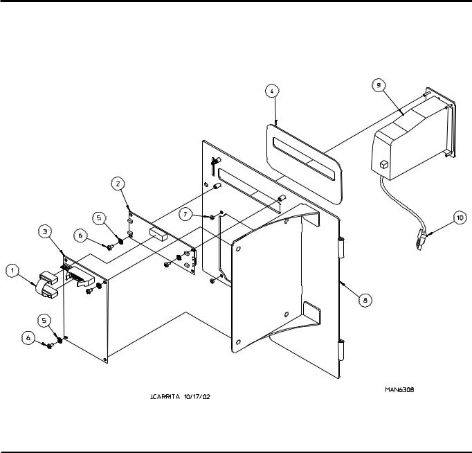
Phase 7 Microprocessor Control Box Assembly
Illus. No. Part No. Qty. Description
Illus. No. |
Part No. |
Qty. |
Description |
1 |
122681 |
1 |
10-Pin Connector |
2 |
122676 |
1 |
8-Pin Connector |
3 |
122646 |
1 |
2-Pin Connector |
4 |
122683 |
1 |
6-Pin Connector (OPL computer Only) |
5 |
122640 |
1 |
9-Pin Connector |
6 |
122706 |
* |
#20-16 U.M.N.L. Socket |
7 |
122669 |
* |
Female Crimp Terminal |
* As needed.
10 |
American Dryer Corporation |
450229-3 |
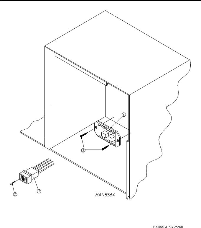
Coin Vault Assembly
|
|
|
|
|
|
|
|
|
|
|
|
Illus. No. |
Part No. |
Qty. |
Description |
|
|
1 |
884050 |
1 |
Microprocessor Coin Vault Assembly Complete |
|
|
|
|
|
|
(includes illus. nos. 1 through 6) |
|
|
|
823143 |
1 |
Microprocessor Coin Vault ONLY |
|
2 |
160028 |
1 |
Cam ONLY for 1/4 Turn Lock |
|
|
3 |
875061 |
1 |
1/4 Turn Lock with Key and Cam |
|
|
|
|
160105* |
1 |
1/4 Turn Mer-Pel Key ONLY |
|
4 |
802020 |
1 |
1/4 Turn Coin Box Assembly |
|
|
|
|
|
|
(includes illus. nos. 2 through 5) |
|
|
|
802019 |
1 |
1/4 Turn Coin Box ONLY without Faceplate |
|
|
|
125915 |
1 |
High Security (Greenwald) Coin Box ONLY with Key |
|
5 |
802018 |
1 |
1/4 Turn Coin Box Faceplate ONLY |
|
|
6 |
152014 |
4 |
1/4-20 Free Spin Wash Nut |
|
|
7 |
102502 |
1 |
Control Door Support Rod |
|
|
8 |
102601 |
1 |
Control Door Rod Retainer Clip |
|
|
9 |
102603 |
1 |
Control Door Rod Support Catch |
|
|
* Specify key number when ordering.
450229-3 |
www.amdry.com |
11 |
Dual Timer Control Box Assembly
|
|
|
|
|
|
|
|
|
|
|
|
|
|
Illus. No. |
Part No. |
Qty. |
Description |
|
|
|
1 |
122641 |
1 |
15-Pin Connector |
|
|
|
2 |
122706 |
15 |
Socket Terminal |
|
|
|
|
|
122801 |
1 |
Pin / Socket Terminal Extraction Tool … Not Illustrated |
|
|
3 |
150301 |
2 |
#8-18 x 7/16” Phillips Pan Head TEK Screw |
|
|
|
4 |
884252 |
1 |
Reversing Timer 24 Volt (for reversing dual timer models Only) |
|
|
|
|
|
|
|
|
|
|
12 |
|
|
|
American Dryer Corporation |
450229-3 |
|
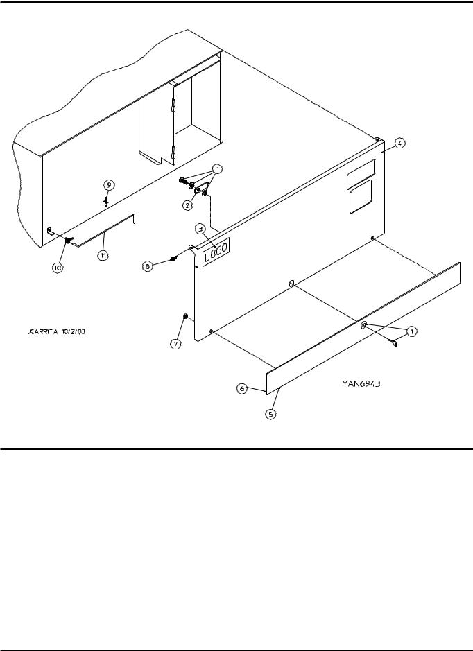
Front Panel Assembly
Illus. No. |
Part No. |
Qty. |
Description |
1* |
801604 |
1 |
Front Panel Assembly |
|
|
|
(for models mfd. as of September 11, 2006) |
|
|
|
(includes illus. nos. 1, 7, and 8) |
|
802267 |
1 |
Front Panel Assembly |
|
|
|
(for models mfd. prior to September 11, 2006) |
|
|
|
(includes illus. nos. 1, 5, and 6) |
2 |
150313 |
11 |
#10-16 x 1/2” TORX PLUS® |
|
150318 |
1 |
25 IP TORX PLUS® Bit 1/4 Hex (for removal of TORX® head screw) |
3 |
881152 |
1 |
Main Door Hinge Block Assembly (top) |
|
881151 |
1 |
Main Door Hinge Block Assembly (bottom) |
4 |
–––––– |
1 |
Lint Drawer Switch |
|
|
|
(refer to Lint Drawer / Lint Drawer Switch Assembly on page 19) |
5 |
881987 |
1 |
Friction Door Latch Kit |
|
|
|
(includes illus. nos. 5 and 6) |
6 |
154215 |
2 |
5/32” Pop Rivet |
7 |
102004 |
2 |
0.750 Round Door Magnet |
8 |
152223 |
2 |
1/2” TORX® Head Screw |
* Specify color when ordering.
450229-3 |
www.amdry.com |
13 |
37-1/4” Main Door Assembly
For Models Mfd. as of September 11, 2006
Illus. No. |
Part No. |
Qty. |
Description |
|
1 |
835128 |
1 |
Main Door Hinge |
|
2 |
314729 |
1 |
Main Door Handle |
|
3 |
102357 |
1 |
Door Gasket |
|
|
170731 |
1 |
Black Adhesive (10.3 oz. cartridge) |
|
4 |
102221 |
1 |
Door Glass |
|
|
170731 |
1 |
Black Adhesive (10.3 oz. cartridge) |
|
5 |
152014 |
6 |
1/4-20 Free Spin Wash Nut |
|
6 |
150683 |
6 |
1/4-20 x 5/8” Carriage Bolt |
|
7 |
801600 |
1 |
Main Door Assembly Complete |
|
8 |
185522 |
2 |
Main Door Magnet Bracket |
|
|
|
|
|
|
14 |
|
|
American Dryer Corporation |
450229-3 |
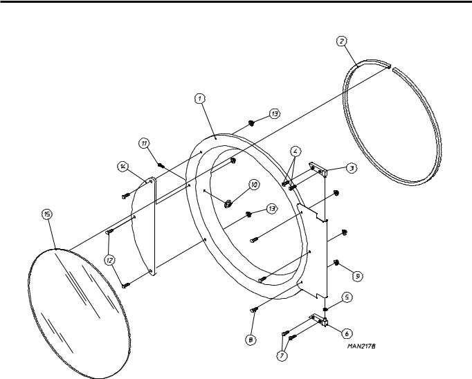
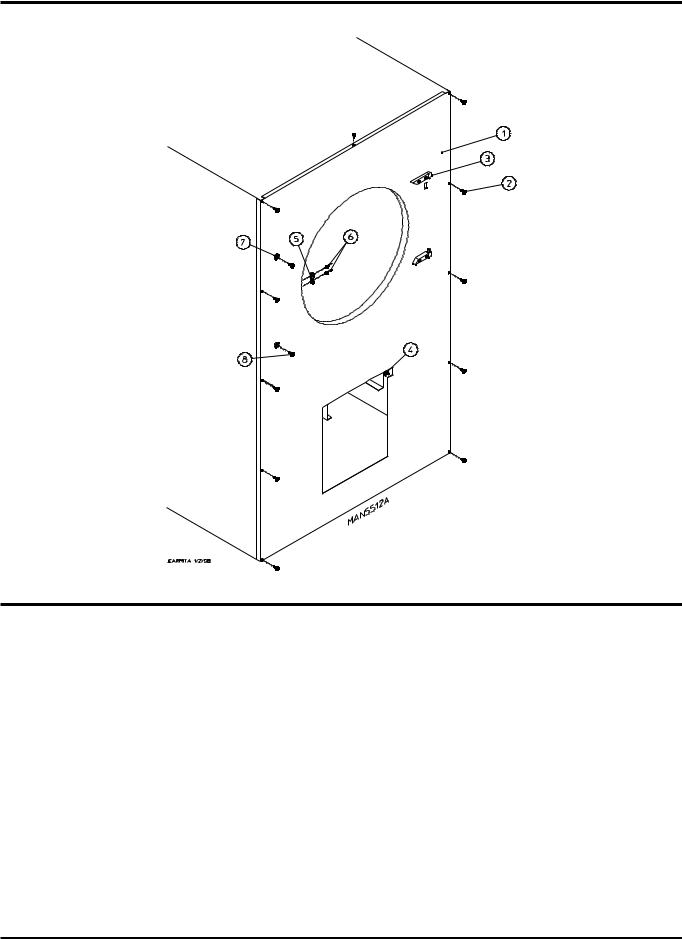
25-1/2” Main Door Assembly
For Models Mfd. prior to September 11, 2006
|
|
|
|
|
|
|
|
|
|
|
|
|
|
|
|
|
|
|
|
|
|
|
|
|
|
|
|
|
|
|
|
|
|
|
|
|
|
|
|
|
|
|
|
|
|
|
|
|
|
|
|
|
|
|
|
|
|
|
|
|
|
|
|
Illus. No. |
Part No. |
Qty. |
Description |
|
|||
1 |
|
881150 |
1 |
Black Main Door Assembly Complete |
|
||
|
|
|
|
(includes illus. nos. 1, 2, and 8 through 15) |
|
||
2 |
|
102354 |
1 |
Door Gasket |
|
||
|
|
170731 |
1 |
Black Gasket Adhesive (10.3 oz. cartridge) |
|
||
3 |
|
881152 |
1 |
Black Top Hinge Block Assembly |
|
||
|
|
|
|
(includes illus. nos. 3 and 4) |
|
||
4 |
|
150445 |
2 |
1/4-20 x 3/4” Black Cap Head Setscrew |
|
||
5 |
|
153031 |
1 |
1/4” Nylon Washer |
|
||
6 |
|
881151 |
1 |
Black Bottom Hinge Block Assembly |
|
||
|
|
|
|
(includes illus. nos. 5 through 7) |
|
||
7 |
|
150445 |
2 |
1/4-20 x 3/4” Black Cap Head Setscrew |
|
||
8 |
|
150683 |
3 |
1/4-20 x 5/8” Black Carriage Bolt |
|
||
9 |
|
152014 |
3 |
1/4-20 Free Spin Wash Nut |
|
||
10 |
151010 |
1 |
#10-32 Black Hex Acorn Nut |
|
|||
11 |
150120 |
1 |
Door Latch Screw |
|
|||
12 |
150683 |
3 |
1/4-20 x 5/8” Black Carriage Bolt |
|
|||
13 |
152014 |
3 |
1/4-20 Free Spin Wash Nut |
|
|||
14 |
881210 |
1 |
Black Main Door Handle ONLY |
|
|||
15 |
102211 |
1 |
20-7/16” Door Glass |
|
|||
|
|
170731 |
1 |
Black Glass Adhesive (10.3 oz. cartridge) |
|
||
|
|
|
|
|
|
|
|
450229-3 |
|
|
|
www.amdry.com |
15 |
||
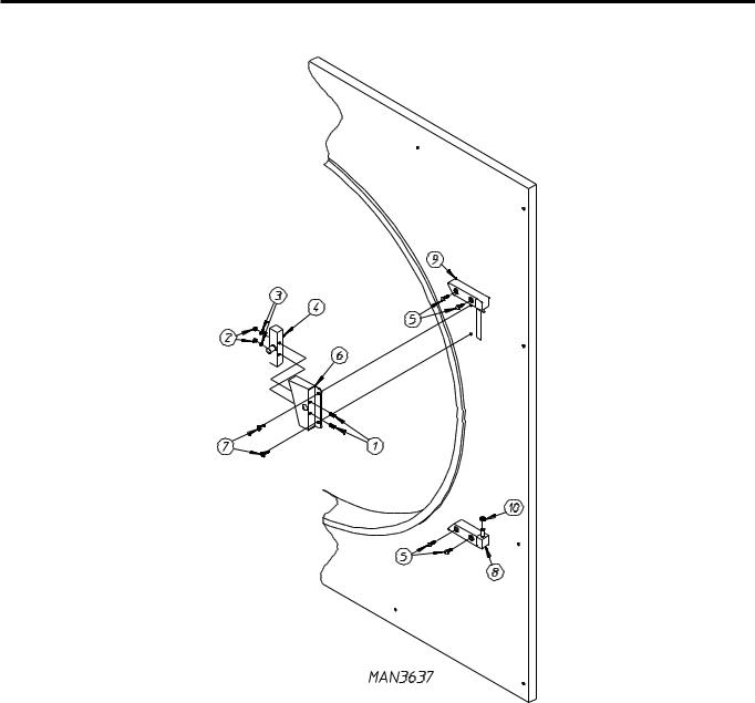
Main Door Switch Assembly
For Models Mfd. as of September 11, 2006
|
|
|
|
|
|
|
|
|
|
|
|
|
|
|
|
|
|
|
|
|
|
|
|
|
|
|
|
|
|
|
|
|
|
|
|
|
|
|
|
|
|
|
|
|
|
|
|
|
|
|
|
|
|
|
|
|
|
|
|
|
|
|
|
|
|
|
|
|
|
|
|
|
|
|
|
|
|
|
|
|
|
|
|
|
|
|
|
|
|
|
|
|
|
|
|
|
|
|
|
|
|
|
|
|
|
|
|
|
|
|
|
Illus. No. |
Part No. |
Qty. |
Description |
|
|||||||||
1 |
150006 |
2 |
#6-32 x 7/8” Phillips Pan Head Machine Screw |
|
|||||||||
2 |
152013 |
2 |
#6-32 Hex Nut |
|
|||||||||
3 |
153010 |
2 |
#6 Star Washer |
|
|||||||||
4 |
137005 |
1 |
Single-Pole Door Switch |
|
|||||||||
5 |
150445 |
4 |
1/4-20 x 3/4” Cap Screw |
|
|||||||||
6 |
882866 |
1 |
Black Main Door Switch Housing |
|
|||||||||
|
883338 |
1 |
Black Main Door Switch with Housing Assembly |
|
|||||||||
|
|
|
(includes illus. nos. 1 through 4 and 6) |
|
|||||||||
7 |
150301 |
2 |
#8-18 x 7/16” Phillips Pan Head TEK Screw |
|
|||||||||
8 |
881151 |
1 |
Bottom Hinge Block |
|
|||||||||
|
|
|
(includes illus. nos. 5, 8, and 10) |
|
|||||||||
9 |
881152 |
1 |
Top Hinge Block |
|
|||||||||
|
|
|
(includes illus. nos. 5 and 9) |
|
|||||||||
10 |
153031 |
1 |
Nylon Washer |
|
|||||||||
|
|
|
|
|
|
|
|
|
|
|
|
|
|
16 |
|
|
|
|
|
|
|
American Dryer Corporation |
450229-3 |
||||
Loading...