


AD-50V Parts Manual
24 VAC Phase 5
American Dryer Corporation
88 Currant Road
Fall River, MA02720-4781
Telephone: (508) 678-9000 / Fax: (508) 678-9447
e-mail: techsupport@amdry.com
www.amdry.com
033000JCARRITA/abe |
ADC Part No. 450345 |

Retain This Manual In A Safe Place For Future Reference
American Dryer Corporation products embody advanced concepts in engineering, design, and safety. If this product is properly maintained, it will provide many years of safe, efficient, and trouble free operation.
ONLY qualified technicians should service this equipment.
OBSERVE ALL SAFETY PRECAUTIONS displayed on the equipment or specified in the installation manual included with the dryer.
The following “FOR YOUR SAFETY” caution must be posted near the dryer in a prominent location.
FOR YOUR SAFETY
Do not store or use gasoline or other flammable vapors and liquids in the vicinity of this or any other appliance.
POUR VOTRE SÉCURITÉ
Ne pas entreposer ni utiliser d’essence ni d’autres vapeurs ou liquides inflammables à proximité de cet appareil ou de tout autre appareil.
We have tried to make this manual as complete as possible and hope you will find it useful. ADC reserves the right to make changes from time to time, without notice or obligation, in prices, specifications, colors, and material, and to change or discontinue models.
Important
For your convenience, log the following information:
DATE OF PURCHASE ____________________________ MODEL NO. |
__________________________________________AD - 50V |
|
RESELLER’S NAME |
_______________________________________________________________________________________ |
|
Serial Number(s) |
________________________________________________________________________________________ |
|
|
________________________________________________________________________________________ |
|
|
________________________________________________________________________________________ |
|
Replacement parts can be obtained from your reseller or the ADC factory. When ordering replacement parts from the factory, you can FAX your order to ADC at (508) 678-9447 or telephone your order directly to the ADC Parts Department at (508) 678-9000. Please specify the dryer model number and serial number in addition to the description and part number, so that your order is processed accurately and promptly.
The illustrations on the following pages may not depict your particular dryer exactly. The illustrations are a composite of the various dryer models. Be sure to check the descriptions of the parts thoroughly before ordering.
“IMPORTANT NOTE TO PURCHASER”
Information must be obtained from your local gas supplier on the instructions to be followed if the user smells gas. These instructions must be posted in a prominent location near the dryer.
Table of Contents |
|
OPL Control DoorAssembly |
|
For Models Mfd. as of July 1, 2002 .................................................................................................... |
3 |
Coin Control DoorAssembly |
|
For Models Mfd. as of July 1, 2002 .................................................................................................... |
4 |
Control DoorAssembly |
|
For Models Mfd. prior to July 1, 2002 ................................................................................................ |
5 |
Phase 5 Coin Microprocessor Control PanelAssembly ....................................................................... |
6, 7 |
Phase 5 OPL Microprocessor Control PanelAssembly ........................................................................... |
8 |
Coin and OPL Control BoxAssembly ..................................................................................................... |
9 |
Coin VaultAssembly ............................................................................................................................. |
10 |
Dual Timer “Tap Touch” Controls |
|
For Models Mfd. as of November 1, 2000 ....................................................................................... |
11 |
DualTimer Control PanelAssembly |
|
For Models Mfd. prior to November 1, 2000 ................................................................................... |
12 |
Non-Microprocessor Coin Meter Control PanelAssembly |
|
For Models Mfd. as of January 25, 2002 .......................................................................................... |
13 |
Non-Microprocessor Coin Meter Control PanelAssembly |
|
For Models Mfd. prior to January 25, 2002 ...................................................................................... |
14 |
Front PanelAssembly |
|
For Models Mfd. with Steel Main Door ............................................................................................ |
15 |
Front PanelAssembly |
|
For Models Mfd. with Plastic Main Door .......................................................................................... |
16 |
Main Door “Steel”Assembly ................................................................................................................ |
17 |
Plastic Main DoorAssembly ................................................................................................................. |
18 |
Main Door SwitchAssembly |
|
For Models Mfd. with Steel Main Door ............................................................................................ |
19 |
Main Door Switch |
|
For Models Mfd. with Plastic Main Door .......................................................................................... |
20 |
Lint Drawer/Lint Drawer SwitchAssemblies |
|
For Models Mfd. as of August 10, 2000 ........................................................................................... |
21 |
Lint Drawer/Lint Drawer SwitchAssemblies |
|
For Models Mfd. prior to August 10, 2000 ....................................................................................... |
22 |
Idler BearingAssembly ......................................................................................................................... |
23 |
Basket (Tumbler) BearingAssembly |
|
For Models Mfd. as of July 17, 2000 .......................................................................................... |
24, 25 |
Basket (Tumbler) BearingAssembly |
|
For Models Mfd. prior to July 17, 2000 ...................................................................................... |
26, 27 |
Basket (Tumbler)/SupportAssemblies ............................................................................................. |
28, 29 |
Non-Reversing T.E.F.C. Motor MountAssembly ............................................................................ |
30, 31 |
Reversing T.E.F.C. Motor MountAssembly .................................................................................... |
32, 33 |
Sensor BracketAssemblies ............................................................................................................. |
34, 35 |
Direct Spark Ignition (DSI) BurnerAssembly |
|
For Models Mfd. as of April 7, 2000 .......................................................................................... |
36, 37 |
Direct Spark Ignition (DSI) BurnerAssembly |
|
For Models Mfd. prior to April 7, 2000 ...................................................................................... |
38, 39 |
Electric OvenAssembly .................................................................................................................. |
40, 41 |
Gas Burner Sail Switch/Hi-LimitAssemblies .......................................................................................... |
42 |
Single-Phase (1ø) Motor, Electric Relay PanelAssembly ....................................................................... |
43 |
3-Phase (3ø) Motor, Electric Relay PanelAssembly ........................................................................ |
44, 45 |
460-480 VAC 3-Phase (3ø) Motor, Electric Relay PanelAssembly ....................................................... |
46 |
Reversing Electric Relay PanelAssembly ............................................................................................... |
47 |
460-480 VAC Reversing Electric Relay PanelAssembly.................................................................. |
48, 49 |
Steam Coil/Air Operated Steam DamperAssembly ......................................................................... |
50, 51 |
Steam Coil/Mechanical Steam DamperAssembly Option ................................................................ |
52, 53 |
Outer Top/Back GuardAssemblies ....................................................................................................... |
54 |
Microprocessor CoinAcceptors Listing ................................................................................................ |
55 |
Coin Meter Replacement Parts ............................................................................................................. |
56 |
Electric Oven ComponentApplication Chart ......................................................................................... |
57 |
Additional PartsAvailable ..................................................................................................................... |
58 |
|
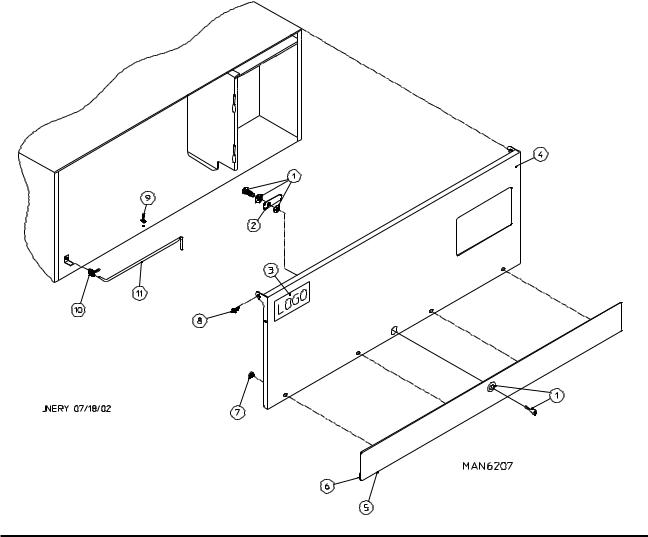
OPL Control Door Assembly |
3 |
||
|
For Models Mfd. as of July 1, 2002 |
|
|
|
|
|
|
|
|
|
|
|
|
|
|
|
|
|
|
|
|
|
|
|
|
|
|
|
|
|
|
|
|
|
|
|
|
|
|
Illus. No. |
Part No. |
Qty. |
Description |
|
1 |
881053 |
1 |
ADC Logo with Tape |
|
|
|
870011 |
1 |
Double Sided Tape Kit |
2 |
883550 |
1 |
White Control Door Assembly |
|
|
|
|
|
(includes illus. nos. 2 and 3) |
|
|
883551 |
1 |
Ivory Control Door Assembly |
|
|
|
|
(includes illus. nos. 2 and 3) |
|
|
883552 |
1 |
Coral Blue Control Door Assembly |
|
|
|
|
(includes illus. nos. 2 and 3) |
3 |
117604 |
3 |
Neoprene Sponge Tape (sold by the foot) |
|
4 |
150317 |
2 |
#10-16 x 3/4” TORX + BTN Type 1 |
|
5 |
102603 |
1 |
Control Door Rod Support Catch |
|
6 |
102601 |
1 |
Control Door Rod Retainer Clip |
|
7 |
102502 |
1 |
Control Door Support Rod |
|
8 |
150321 |
2 |
#10-32 x 1/2” Phillips Machine Screw |
|
|
9 |
154011 |
2 |
#10-32 Multi-Thread U-Nut |
Telephone: (508) 678-9000 |
Fax: (508) 678-9447 |
4 |
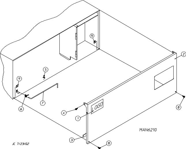
Coin Control Door Assembly |
|
For Models Mfd. as of July 1, 2002 |
Illus. No. |
Part No. |
Qty. |
Description |
1 |
160015 |
1 |
High Security Lock Assembly |
|
160104 |
1 |
Key ONLY |
2 |
160016 |
1 |
Lock Cam ONLY |
3 |
881053 |
1 |
ADC Logo with Tape |
4 |
883477 |
1 |
White Control Door Assembly with Black Trim |
|
|
|
(includes illus. nos. 4 through 7) |
|
883478 |
1 |
Ivory Control Door with Black Trim |
|
|
|
(includes illus. nos. 4 through 7) |
|
883549 |
1 |
Coral Blue Control Door with Black Trim |
|
|
|
(includes illus. nos. 4 through 7) |
5 |
883476 |
1 |
Black Trim Strip with Lock Hole |
6 |
117604 |
6 |
Neoprene Sponge Tape (sold by the foot) |
7 |
152014 |
4 |
1/4-20 with 3/4” Free Spin Wash Nut |
8 |
150317 |
2 |
#10-16 x 3/4” TORX + BTN Type 1 |
9 |
102603 |
1 |
Control Door Rod Support Catch |
10 |
102601 |
1 |
Control Door Rod Retainer Clip |
11 |
102502 |
1 |
Control Door Support Rod |
American Dryer Corporation |
88 Currant Road / Fall River, MA 02720-4781 |
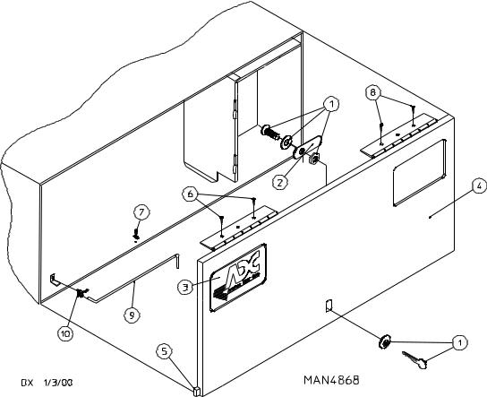
Control Door Assembly |
5 |
|
For Models Mfd. prior to July 1, 2002 |
|
|
|
|
|
|
|
|
Illus. No. |
Part No. |
Qty. |
Description |
1 |
160015 |
1 |
High Security MK-100 Lock Assembly with Key |
|
|
|
(for coin models Only) |
|
160017 |
1 |
Special Dummy Lock ONLY |
|
|
|
(for non-coin models Only) |
|
160104 |
1 |
MK-100 Key ONLY |
2 |
160052 |
1 |
Lock Cam ONLY |
3 |
881053 |
1 |
ADC Logo with Tape |
|
870011 |
1 |
Double Sided Tape Kit |
4 |
882511 |
1 |
White High Security Control Door Assembly Less Lock |
|
|
|
(includes illus. nos. 4 and 5) |
|
882513 |
1 |
Almond “B” High Security Control Door Assembly Less Lock |
|
|
|
(includes illus. nos. 4 and 5) |
|
882512 |
1 |
Coral Blue High Security Control Door Assembly Less Lock |
|
|
|
(includes illus. nos. 4 and 5) |
|
882509 |
1 |
Stainless Steel High Security Control Door Assembly Less Lock |
|
|
|
(includes illus. nos. 4 and 5) |
5 |
117603 |
3 |
Noise Suppressor Tape (sold by the foot) |
6 |
150300 |
2 |
#10-16 x 1/2” Hex Washer TEK Screw |
7 |
102603 |
1 |
Control Door Rod Support Catch |
8 |
150300 |
2 |
#10-16 x 1/2” Hex Washer TEK Screw |
9 |
102502 |
1 |
Control Door Support Rod |
10 |
102601 |
1 |
Control Door Rod Retainer Clip |
Telephone: (508) 678-9000 |
Fax: (508) 678-9447 |
6 |
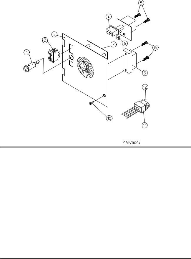
Phase 5 Coin Microprocessor Control Panel Assembly |
|||||||
|
|
|
|
|
|
|
|
|
|
|
|
|
|
|
|
|
|
|
|
|
|
|
|
|
|
|
|
|
|
|
|
|
|
|
|
|
|
|
|
|
|
|
|
|
|
|
|
|
|
|
|
|
|
|
|
|
|
|
|
|
|
|
|
|
|
|
|
|
|
|
|
|
|
|
|
|
|
|
|
|
|
|
|
|
|
|
|
|
|
American Dryer Corporation |
88 Currant Road / Fall River, MA 02720-4781 |

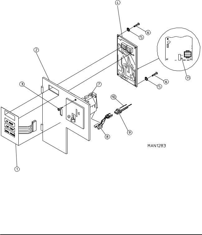
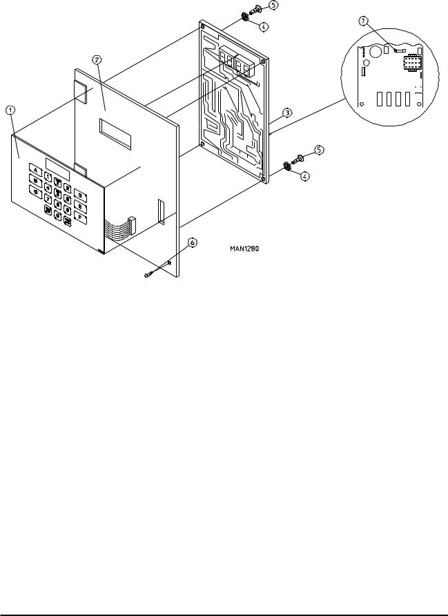
Phase 5 Coin Microprocessor Control Panel Assembly |
7 |
Illus. No. |
Part No. |
Qty. |
Description |
1 |
112526 |
1 |
Coin Keyboard Label Assembly |
2 |
883537 |
1 |
Phase 5 Coin Control Panel Assembly |
|
|
|
(includes illus. nos. 1, 2, and 4 through 6) |
|
|
|
(for models mfd. as of June 25, 2002) |
|
883538 |
1 |
Phase 5 Coin Control Panel Assembly with Battery Option |
|
|
|
(includes illus. nos. 1, 2, and 4 through 6) |
|
|
|
(for models mfd. as of June 25, 2002) |
|
883582 |
1 |
Phase 5 Coin Control Panel Assembly with Battery Option |
|
|
|
(includes illus. nos. 1, 2, and 4 through 6) |
|
|
|
(for models mfd. prior to June 25, 2002) |
|
883581 |
1 |
Phase 5 Coin Control Panel Assembly |
|
|
|
(includes illus. nos. 1, 2, and 4 through 6) |
|
|
|
(for models mfd. prior to June 25, 2002) |
|
883539 |
1 |
Coin Control Panel ONLY |
|
|
|
(for models mfd. as of June 25, 2002) |
|
883540 |
1 |
Coin Control Panel ONLY with Battery Bracket |
|
|
|
(for models mfd. as of June 25, 2002) |
|
883580 |
1 |
Coin Control Panel ONLY |
|
|
|
(for models mfd. prior to June 25, 2002) |
|
883579 |
1 |
Coin Control Panel ONLY with Battery Bracket |
|
|
|
(for models mfd. prior to June 25, 2002) |
3 |
150309 |
1 |
#10-16 x 1/2” Hex Head TEK Crimptite Screw |
4 |
137213 |
1 |
Phase 5 Coin Controller ONLY |
|
824998 |
1 |
Phase 5 Battery Clip |
5 |
153010 |
2 |
#6 Star Washer |
6 |
150005 |
2 |
#6-32 x 1/4” Phillips Round Head Machine Screw |
7 |
--------- |
1 |
Microprocessor Coin Acceptor |
|
|
|
(refer to Microprocessor Coin Acceptors Listing on page 55) |
8 |
-------- |
1 |
Optic Switch ONLY |
|
|
|
(refer to Microprocessor Coin Acceptors Listing on page 55) |
9 |
137023 |
1 |
Optic Switch Connector ONLY |
10 |
137021 |
3 |
Microprocessor Socket ONLY |
|
880772 |
1 |
Single Coin Optical Switch Harness |
|
122800 |
1 |
Microprocessor (female) Pin Extraction Tool |
11 |
136048 |
1 |
1/8-Amp (Slo-Blo) Fuse |
IMPORTANT: Check label on computer chip to verify correct part number of controller (computer).
Telephone: (508) 678-9000 |
Fax: (508) 678-9447 |
|
8 |
Phase 5 OPL Microprocessor Control Panel Assembly |
|
|||||||||
|
|
|
|
|
|
|
|
|
|
|
|
|
|
|
|
|
|
|
|
|
|
|
|
|
|
|
|
|
|
|
|
|
|
|
|
|
|
|
|
|
|
|
|
|
|
|
|
|
|
|
|
|
|
|
|
|
|
|
|
|
|
|
|
|
|
|
|
|
|
|
|
|
|
|
|
|
|
|
|
|
|
|
|
|
|
|
|
|
|
|
|
|
|
|
|
|
|
|
|
|
|
|
|
|
|
|
|
|
|
|
|
|
|
|
|
|
|
|
|
|
|
|
|
|
|
|
|
|
|
|
|
|
|
|
|
|
|
|
|
|
|
|
|
|
|
|
|
|
|
|
|
|
|
|
|
Illus. No. |
Part No. |
Qty. |
Description |
1 |
112535 |
1 |
OPL English Keyboard Label Assembly |
|
112276 |
1 |
OPL Stick-On Labels (English ONLY)...Not Illustrated |
|
112275 |
1 |
3-Language OPL Stick-On Labels |
|
|
|
(Spanish, Italian, and Hebrew)...Not Illustrated |
|
112277 |
1 |
3-Language OPL Stick-On Labels |
|
|
|
(English, Spanish, and Hebrew)...Not Illustrated |
|
112278 |
1 |
5-Language OPL Stick-On Labels |
|
|
|
(Italian, Dutch, French, German, and Chinese)...Not Illustrated |
2 |
801255 |
1 |
Phase 5 Microprocessor Control Panel ONLY |
|
801256 |
1 |
Phase 5 Microprocessor Control Panel ONLY with Battery Bracket |
|
801206 |
1 |
Phase 5 OPL Non-Reversing Microprocessor Control Panel |
|
|
|
Assembly Complete |
|
|
|
(includes illus. nos. 1 through 6) |
|
801207 |
1 |
Phase 5 OPL Reversing Microprocessor Control Panel Assembly Complete |
|
|
|
(includes illus. nos. 1 through 6) |
3 |
137222 |
1 |
Phase 5 OPL Non-Reversing Controller ONLY |
|
137231 |
1 |
Phase 5 OPL Reversing Controller ONLY |
|
824998 |
1 |
Phase 5 Battery Clip |
4 |
153010 |
2 |
#6 Star Washer |
5 |
150005 |
2 |
#6-32 x 1/4” Phillips Round Head Machine Screw |
6 |
150309 |
1 |
#10-16 x 1/2” Hex Head TEK Crimptite Screw |
7 |
136048 |
1 |
1/8-Amp (Slo-Blo) Fuse |
IMPORTANT: Check label on computer chip to verify correct part number for controller (computer).
American Dryer Corporation |
88 Currant Road / Fall River, MA 02720-4781 |
Coin and OPL Control Box Assembly |
9 |
||
|
|
|
|
|
|
|
|
|
|
|
|
|
|
|
|
|
|
|
|
Illus. No. |
Part No. |
Qty. |
Description |
1 |
132002 |
1 |
Transformer |
|
|
|
(for mechanical steam damper models - 208 VAC and higher Only) |
2 |
150300 |
2 |
#10-16 x 1/2” Hex Washer TEK Screw |
3 |
150301 |
2 |
#8-18 x 7/16” Phillips Pan Head TEK Screw |
4 |
131931 |
1 |
Steam Valve Relay - 24 VAC |
|
|
|
(for mechanical steam damper models Only) |
5 |
137035 |
1 |
Motor Capacitor |
|
|
|
(for mechanical steam damper models Only) |
6 |
323583 |
1 |
Capacitor Bracket |
|
|
|
(for mechanical steam damper models Only) |
7 |
150300 |
2 |
#10-16 x 1/2” Hex Washer TEK Screw |
8 |
122641 |
1 |
15-Pin Microprocessor Controller (computer) Connector |
9 |
122706 |
* |
Socket Terminal ONLY |
-- |
122801 |
1 |
Pin/Socket Extraction Tool |
*As required.
Telephone: (508) 678-9000 |
Fax: (508) 678-9447 |
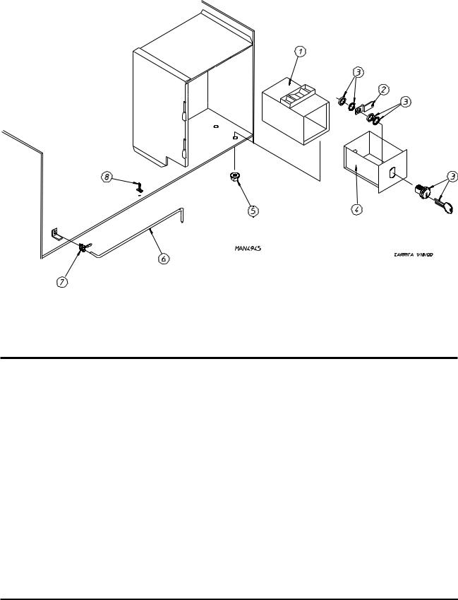
10 |
Coin Vault Assembly |
Illus. No. |
Part No. |
Qty. |
Description |
1 |
802112 |
1 |
Microprocessor Coin Vault Assembly Complete |
|
|
|
(includes illus. nos. 1 through 5) |
|
802117 |
1 |
Microprocessor Coin Vault ONLY |
|
802110 |
1 |
Non-Microprocessor Coin Vault Assembly Complete |
|
|
|
(includes illus. nos. 1 through 5) |
|
802115 |
1 |
Non-Microprocessor Coin Vault ONLY |
2 |
160028 |
1 |
Cam for 1/4 Turn Lock ONLY |
3 |
875061 |
1 |
1/4 Turn Lock with Key and Cam |
|
160105* |
1 |
1/4 Turn Mer-Pel Key ONLY |
4 |
802020 |
1 |
1/4 Turn Coin Box Assembly |
|
|
|
(includes illus. nos. 2 through 4) |
5 |
152014 |
4 |
1/4-20 Free Spin Wash Nut |
6 |
102502 |
1 |
Control Door Support Rod |
7 |
102601 |
1 |
Control Door Rod Retainer Clip |
8 |
102603 |
1 |
Control Door Rod Catch |
*Specify key number when ordering.
American Dryer Corporation |
88 Currant Road / Fall River, MA 02720-4781 |

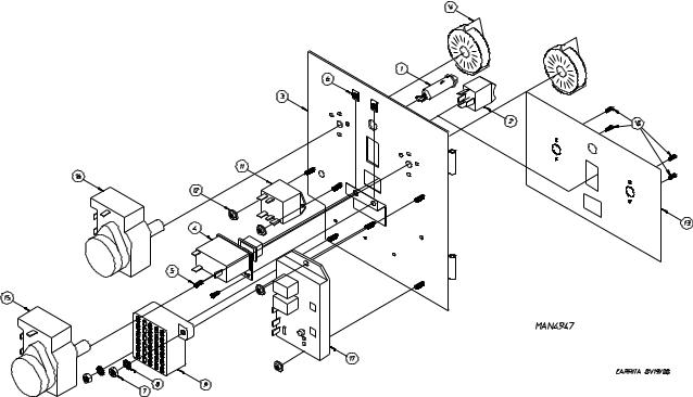
Dual Timer “Tap Touch” Controls |
11 |
For Models Mfd. as of November 1, 2000 |
|
Illus. No. |
Part No. |
Qty. |
Description |
1 |
824298 |
1 |
15 Minute Timer - 24 VAC |
2 |
824299 |
1 |
60 Minute Timer - 24 VAC |
3 |
824175 |
1 |
Red Pilot Light - 24 VAC |
4 |
122301 |
1 |
“Tap Touch” Switch |
5 |
131932 |
3 |
Relay SPST 24v |
6 |
120730 |
1 |
30-Position Terminal Block |
7 |
151000 |
6 |
#6-32 Pal Nut |
8 |
882903 |
1 |
Dual Timer Panel Complete |
|
|
|
(includes illus. nos. 1 through 15) |
|
850392 |
- |
Dual Timer Panel ONLY |
9 |
153010 |
2 |
#6 Star Washer |
10 |
152000 |
3 |
#6-32 Hex Nut |
11 |
150207 |
2 |
#10-24 x 1/2” Phillips Pan Head Machine Screw |
12 |
150110 |
4 |
#8-32 x 1/4” Phillips Round Head Machine Screw |
13 |
112563 |
1 |
Dual Timer Panel Overlay |
14 |
124104 |
1 |
Pure Touch Knob with Red Pointer |
15 |
124105 |
1 |
Pure Touch Knob with Blue Pointer |
Telephone: (508) 678-9000 |
Fax: (508) 678-9447 |
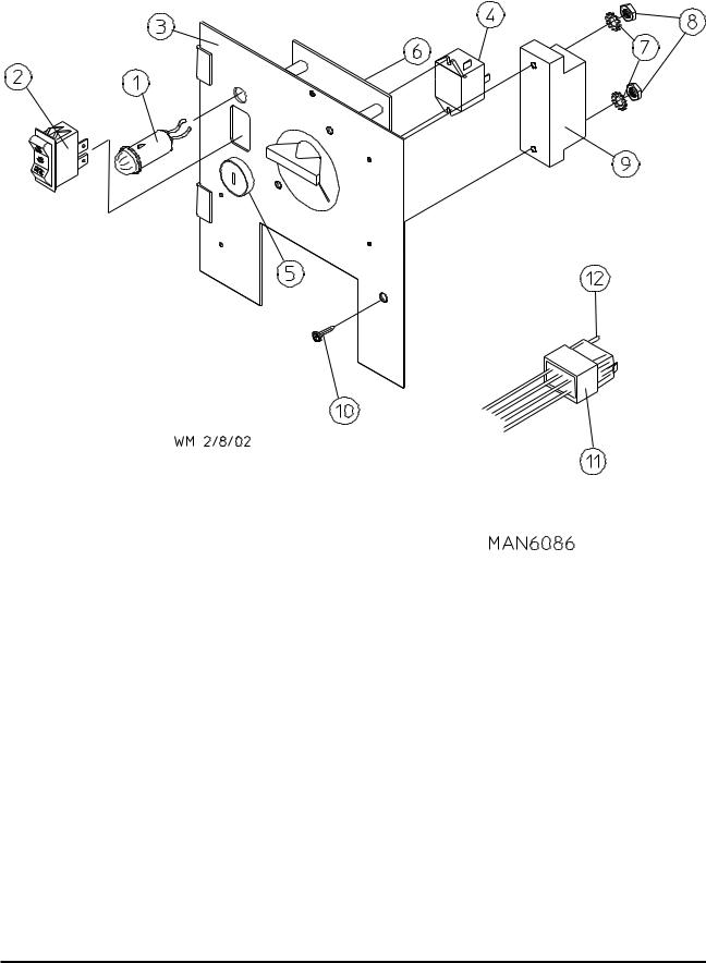
12 |
Dual Timer Control Panel Assembly |
||
|
|
For Models Mfd. prior to November 1, 2000 |
|
|
|
|
|
|
|
|
|
|
|
|
|
|
|
|
|
|
|
|
|
Illus. No. |
Part No. |
Qty. |
Description |
1 |
123005 |
1 |
Red Indicator Light - 24 VAC |
2 |
122400 |
1 |
Rocker Heat Selector Switch |
3 |
882596 |
1 |
Dual Timer Control Panel Assembly Complete - 24 VAC |
|
|
|
(includes illus. nos. 1 through 16) |
|
882600 |
1 |
Dual Timer Reversing Control Panel Assembly Complete - 24 VAC |
|
|
|
(includes illus. nos. 1 through 17) |
|
850456 |
1 |
Dual Timer Control Panel ONLY |
4 |
131917 |
1 |
Push-To-Start Relay - 24 VAC |
5 |
150207 |
2 |
#10-24 x 1/2” Phillips Pan Head Machine Screw |
6 |
154001 |
2 |
#10-24 Speed Nut |
7 |
152000 |
2 |
#6-32 Hex Nut |
8 |
153010 |
2 |
#6 Star Washer |
9 |
120730 |
1 |
30-Position Terminal Block |
10 |
150110 |
4 |
#8-32 x 1/4” Phillips Round Head Machine Screw |
11 |
131932 |
1 |
Dual Timer Relay - 24 VAC |
12 |
151000 |
4 |
#6-32 Pal Nut |
13 |
112050 |
1 |
Dual Timer Label ONLY |
14 |
124103 |
2 |
Arrow Timer Knob |
15 |
124025 |
1 |
60-Minute Timer - 24 VAC |
16 |
124030 |
1 |
15-Minute Timer - 24 VAC |
17 |
132198 |
1 |
Reversing Timer - 24 VAC |
-- |
882540 |
1 |
Panel Wiring (non-reversing panel)...Not Illustrated |
-- |
882573 |
1 |
Panel Wiring (reversing panel)...Not Illustrated |
American Dryer Corporation |
88 Currant Road / Fall River, MA 02720-4781 |
Non-Microprocessor Coin Meter Control Panel Assembly |
13 |
|
||
For Models Mfd. as of January 25, 2002 |
|
|
||
|
|
|
|
|
|
|
|
|
|
|
|
|
|
|
|
|
|
|
|
|
|
|
|
|
Illus. No. |
Part No. |
Qty. |
Description |
1 |
123005 |
1 |
Red Indicator Light - 24 VAC |
2 |
122400 |
1 |
Rocker Heat Selector Switch |
3 |
824172 |
1 |
Coin Meter Control Panel Assembly Less Coin Meter |
|
|
|
(includes illus. nos. 2 through 5, 7, and 8) |
|
824109 |
1 |
Coin Meter Control Panel ONLY |
4 |
131932 |
1 |
24 VAC Relay |
|
154001 |
2 |
#10-24 Speed Nut (used on P/N: 131932, 24 VAC relay) |
5 |
123225 |
1 |
Green Push-To-Start Button |
6 |
125601 |
1 |
25¢ Coin Meter - 24 VAC (specify timing) |
7 |
153010 |
2 |
#6 Star Washer |
8 |
152016 |
2 |
#4-40 Hex Nut |
9 |
120712 |
1 |
12-Position Terminal Block |
10 |
150300 |
1 |
#10-16 x 1/2” Hex Washer TEK Screw |
11 |
122602 |
1 |
9-Pin Connector |
12 |
122700 |
7 |
Pin Terminal ONLY |
-- |
122801 |
1 |
Pin Extraction Tool |
NOTE: For Coin Meter Replacement Parts refer to page 56.
Telephone: (508) 678-9000 |
Fax: (508) 678-9447 |
14 |
Non-Microprocessor Coin Meter Control Panel Assembly |
|
For Models Mfd. prior to January 25, 2002 |
Illus. No. |
Part No. |
Qty. |
Description |
1 |
123005 |
1 |
Red Indicator Light - 24 VAC |
2 |
122400 |
1 |
Rocker Heat Selector Switch |
3 |
824020 |
1 |
Coin Meter Control Panel Assembly Complete - 24 VAC |
|
|
|
(includes illus. nos. 1 through 6 and 8 through 12) |
|
800054 |
1 |
Coin Meter Control Panel ONLY |
4 |
131917 |
1 |
Push-To-Start Relay - 24 VAC |
5 |
150207 |
2 |
#10-24 x 1/2” Round Head Machine Screw |
6 |
154001 |
2 |
#10-24 Speed Nut |
7* |
125601 |
1 |
25¢ Coin Meter - 24 VAC (specify timing) |
8 |
150303 |
2 |
#4 x 3/4” Pan Head “A” Screw |
9 |
120712 |
1 |
12-Position Terminal Block |
10 |
150309 |
1 |
#10-16 x 1/2” Hex Head TEK Crimptite Screw |
11 |
122602 |
1 |
9-Pin Connector ONLY |
12 |
122700 |
9 |
Pin Terminal ONLY |
--- |
122801 |
1 |
Pin/Socket Extraction Tool |
*Consult factory for coin meters not listed.
NOTE: For Coin Meter Replacement Parts refer to page 56.
American Dryer Corporation |
88 Currant Road / Fall River, MA 02720-4781 |
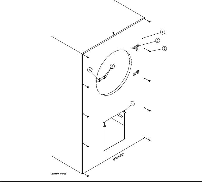
Front Panel Assembly |
15 |
For Models Mfd. with Steel Main Door |
|
Illus. No. |
Part No. |
Qty. |
Description |
1 |
883137 |
1 |
White Front Panel Assembly |
|
|
|
(includes illus. nos. 1, 3, 5, and 6) |
|
883138 |
1 |
Coral Blue Front Panel Assembly |
|
|
|
(includes illus. nos. 1, 3, 5, and 6) |
|
883139 |
1 |
Ivory Front Panel Assembly |
|
|
|
(includes illus. nos. 1, 3, 5, and 6) |
2 |
150313 |
11 |
#10-16 x 1/2” TORX Plus BTN Type 1 |
|
150318 |
1 |
25 IP TORX Plus Bit 1/4 Hex (for removal of TORX head screw) |
3 |
-------- |
1 |
Main Door Hinge |
4 |
-------- |
1 |
Lint Drawer Switch |
|
|
|
(refer to Lint Drawer/Lint Drawer Switch Assemblies |
|
|
|
on page 21 and page 22) |
5 |
170330 |
1 |
Friction Door Latch |
6 |
154215 |
2 |
5/32” Pop Rivet |
Telephone: (508) 678-9000 |
Fax: (508) 678-9447 |
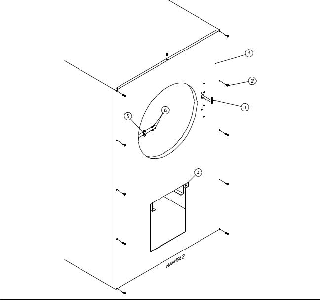
16 |
Front Panel Assembly |
|
For Models Mfd. with Plastic Main Door |
Illus. No. |
Part No. |
Qty. |
Description |
1 |
882525 |
1 |
White Right Hand Front Panel Assembly |
|
|
|
(includes illus. nos. 1, 3, 5, and 6) |
|
882527 |
1 |
Almond “B” Right Hand Front Panel Assembly |
|
|
|
(includes illus. nos. 1, 3, 5, and 6) |
|
882528 |
1 |
Coral Blue Right Hand Front Panel Assembly |
|
|
|
(includes illus. nos. 1, 3, 5, and 6) |
2 |
150309 |
11 |
#10-16 x 1/2” Hex Head TEK Crimptite Screw |
3 |
121405 |
1 |
Rubber Grommet |
4 |
-------- |
1 |
Lint Drawer Switch |
|
|
|
(refer to Lint Drawer/Lint Drawer Switch Assemblies |
|
|
|
on page 21 and page 22) |
5 |
170330 |
1 |
Friction Door Latch |
6 |
154215 |
2 |
5/32” Pop Rivet |
American Dryer Corporation |
88 Currant Road / Fall River, MA 02720-4781 |
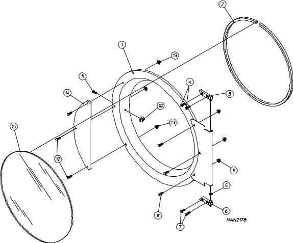
Main Door “Steel” Assembly |
17 |
|||
|
|
|
|
|
|
|
|
|
|
|
|
|
|
|
|
|
|
|
|
|
|
|
|
|
|
|
|
|
|
|
|
|
|
|
|
|
|
|
|
|
|
|
|
|
Illus. No. |
Part No. |
Qty. |
Description |
1 |
881150 |
1 |
Black Main Door Assembly Complete |
|
|
|
(includes illus. nos. 1, 2, and 8 through 15) |
2 |
102354 |
1 |
Door Gasket |
|
170731 |
1 |
Black Gasket Adhesive (10.7 oz. cartridge) |
3 |
881152 |
1 |
Black Top Hinge Block Assembly |
|
|
|
(includes illus. nos. 3 and 4) |
4 |
150445 |
2 |
1/4-20 x 3/4” Black Cap Head Setscrew |
5 |
153031 |
1 |
1/4” Nylon Washer |
6 |
881151 |
1 |
Black Bottom Hinge Block Assembly |
|
|
|
(includes illus. nos. 5 through 7) |
7 |
150445 |
2 |
1/4-20 x 3/4” Black Cap Head Setscrew |
8 |
150683 |
3 |
1/4-20 x 5/8” Black Carriage Bolt |
9 |
152014 |
3 |
1/2-20 Free Spin Wash Nut |
10 |
151010 |
1 |
#10-32 Black Hex Acorn Nut |
11 |
150120 |
1 |
Door Latch Screw |
12 |
150683 |
3 |
1/4-20 x 5/8” Black Carriage Bolt |
13 |
152014 |
3 |
1/2-20 Free Spin Wash Nut |
14 |
881210 |
1 |
Black Main Door Handle ONLY |
15 |
102211 |
1 |
20-7/16” Door Glass |
|
170731 |
1 |
Black Glass Adhesive (10.3 oz. cartridge) |
Telephone: (508) 678-9000 |
Fax: (508) 678-9447 |
 Loading...