


 Loading...
Allied Telesis X900-24XT-N, X900-48FE-N, AT-9924SP, X900-48FS, AT-8948 User Manual
...x900 Series Switch and SwitchBlade® x908
Installation and Safety Guide
AT-8948 x900-48FE x900-48FE-N x900-48FS AT-9924T AT-9924SP AT-9924Ts x900-12XT/S x900-24XT x900-24XT-N x900-24XS SwitchBlade® x908

x900 Series Switch and SwitchBlade® x908
Installation and Safety Guide
AT-8948 |
AT-9924Ts |
x900-48FE |
x900-12XT/S |
x900-48FE-N |
x900-24XT |
x900-48FS |
x900-24XT-N |
AT-9924T |
x900-24XS |
AT-9924SP |
SwitchBlade® x908 |
Download the complete document set from
www.alliedtelesis.com/support/software
x900 Series Switch and SwitchBlade® x908
x900 Series Switch and SwitchBlade® x908 Installation and Safety Guide Document Number C613-04052-00 REV P
© 2011 Allied Telesis, Inc. All rights reserved. No part of this publication may be reproduced without prior written permission from Allied Telesis, Inc.
Allied Telesis, Inc. reserves the right to change specifications and other information in this document without prior written notice. The information provided herein is subject to change without notice. In no event shall Allied Telesis, Inc. be liable for any incidental, special, indirect, or consequential damages whatsoever, including but not limited to lost profits, arising out of or related to this manual or the information contained herein, even if Allied Telesis, Inc. has been advised of, known, or should have known, the possibility of such damages.
Allied Telesis, AlliedWare, AlliedWare Plus, and SwitchBlade are trademarks or registered trademarks in the United States and elsewhere of Allied Telesis, Inc. Adobe, Acrobat, and Reader are either registered trademarks or trademarks of Adobe Systems Incorporated in the United States and/or other countries.
Microsoft and Visio are either registered trademarks or trademarks of Microsoft Corporation in the United States and/or other countries. Additional brands, names and products mentioned herein may be trademarks of their respective companies.
2

|
Installation and Safety Guide |
Contents |
|
About this Guide .............................................................................................................. |
4 |
Package Contents ............................................................................................................. |
4 |
Selecting a Site .............................................................................................................. |
..... 6 |
Installing the Switch ......................................................................................................... |
7 |
Applying Power to the Switch ..................................................................................... |
11 |
Connecting to the Switch ............................................................................................. |
17 |
Checking LEDs ................................................................................................................ |
25 |
Obtaining Documentation and Resources ............................................................... |
30 |
Standards ..................................................................................................................... |
..... 32 |
Safety ........................................................................................................................ |
......... 33 |
Sicherheit .................................................................................................................... |
...... 35 |
Sikkerhed ..................................................................................................................... |
..... 37 |
Veiligheid .................................................................................................................... |
....... 39 |
Sécurité ...................................................................................................................... |
....... 41 |
Turvallisuus .................................................................................................................. |
..... 43 |
Norme di Sicurezza ........................................................................................................ |
45 |
Sikkerhet ..................................................................................................................... |
...... 47 |
Segurança ..................................................................................................................... |
..... 49 |
Seguridad ..................................................................................................................... |
..... 51 |
Säkerhet ...................................................................................................................... |
...... 53 |
3

x900 Series Switch and SwitchBlade® x908
About this Guide
This Installation and Safety Guide describes how to install and log in to the following switches:
■ |
AT-8948 |
■ |
x900-12XT/S |
■ |
x900-48FE |
■ |
AT-9924Ts |
■ x900-48FE-N |
■ |
x900-24XT |
|
■ |
x900-48FS |
■ x900-24XT-N |
|
■ |
AT-9924T |
■ |
x900-24XS |
■ |
AT-9924SP |
■ |
SwitchBlade® x908 |
You can download the complete document set for x900 Series switches and SwitchBlade x908 from www.alliedtelesis.com/support/software. For more information about the document set and other resources, see “Obtaining Documentation and Resources” on page 30.
Package Contents
Depending on the model, the switch is factory-fitted with the following power supply and fan options:
■AT-8948, AT-9924Ts, x900-24XT, x900-24XT-N, and x900-24XS switches have a PSU and a FOM installed.
■AT-9924T, AT-9924SP, x900-48FE, x900-48FE-N, and x900-48FS switches have a PSU and a blanking plate installed.
■x900-12XT/S has a fixed PSU installed.
■SwitchBlade x908 has dual chassis fan modules and blanking plates installed, but no PSUs. Power supplies must be ordered separately.
Power supply units (PSU) can be:
■AT-PWR01, either AC or DC power supply unit
■AT-PWR02, AC only power supply unit
■AT-PWR05, either AC or DC power supply unit
How to install a PSU or fan in the switch is described in the Removable Power Supply and Fan Installation Guide.
4
Installation and Safety Guide
The following items are shipped with each switch. Contact your authorised distributor or reseller if any are damaged or missing.
All models ship with:
■one cable for connecting the switch to a terminal or PC
■two rack-mount brackets
■depending on the switch, an appropriate number of M4 screws for rack-mount brackets
■this Installation and Safety Guide
■one warranty card
All models except the SwitchBlade x908 also ship with:
■AC power cord(s) (AC models only)
■one power cord retaining kit (AC models only)
•1 retaining clip
•2 retaining plates
•2 screws
■depending on the switch, four or five rubber feet with screws for mounting the switch on a level surface
Some products also ship with a Documentation and Tools CD-ROM containing documentation and utilities. For more information, see “Obtaining Documentation and Resources” on page 30.
5

x900 Series Switch and SwitchBlade® x908
Selecting a Site
Before you install the switch, review the following considerations about its location.
■AT-8948, x900-48FE, x900-48FS, and AT-9900 switches require an ambient temperature from 0ºC to 50ºC (32ºF to 122ºF).
■AT-9924Ts, x900-12XT/S, x900-24XT, x900-24XT-N, x900-24XS, and SwitchBlade x908 switches require an ambient temperature from 0ºC to 40ºC (32ºF to 104ºF).
■There should be adequate airflow around the switch and its vents.
■The site should be dust-free and without moisture.
■Humidity can be from 5% to 80% non-condensing.
■You need a reliable and earthed (grounded) power supply source, preferably dedicated and filtered.
■Cabling must not be exposed to sources of electrical noise, such as radio transmitters, broadband amplifiers, power lines, electric motors, and fluorescent fixtures.
■Switch ports are suitable for intra-building connections, or where non-exposed cabling is required.
■Related network devices can be connected to the switch but cannot exceed maximum cable lengths specified in the Hardware Reference.
■You may need to remove cabinet doors from the equipment rack to accommodate cords and cables.
■Ensure easy access to the switch’s power and cable connections.
■The SwitchBlade x908 should only be installed in locations where access to the system is controlled. The SwitchBlade x908 is not intended for home use. If installed in a school, it should only be installed in a location restricted to service personnel.
6

Installation and Safety Guide
Installing the Switch
Ports on the switch are suitable only for connections within buildings (intrabuilding) and with cables unexposed to the outside.
You can install the switch on a level surface, such as a desktop or bench, or in a standard 19-inch rack. Some switches are heavier at the rear than at the front. Use the brackets supplied with the switch when rack-mounting because they are designed to fully support the weight.
Before you begin
■Read the safety information.
For your well-being and that of the equipment, read the safety information in this document. You can also download this document from www.alliedtelesis.com/support/software.
■Verify the package contents if you have not already done so.
See “Package Contents” on page 4. If any items are damaged or missing, contact your authorised distributor or reseller.
■Gather necessary tools and equipment:
•Phillips #2 screwdriver to loosen the blanking plate, if any.
•Rack-mount screws and nuts, and a suitable screwdriver. The SwitchBlade x908 requires eight sets of screws and nuts. All other switches required four sets.
•For DC installations, you need an appropriate DC power source, DC supply cable, ring connectors, and a crimp tool for screw terminal style connectors or appropriate connectors for the PSU model.
■Prepare the cabinet in a suitable location
Follow guidelines described in “Selecting a Site” on page 6 to choose an appropriate location and modify the rack as necessary.
■Because the switch is deep, we recommend two people mount the switch in the rack and tighten the screws.
Preparation for NEBS
For Network Equipment Building System (NEBS) installations of the x900-24XT-N, do the following to ensure rack-mounted installations are earthed:
■Remove non-conductive coatings, such as lacquer and enamel, from the rack rail where hardware will contact it. Remove coatings from unplated connectors, braided strap, and bus bars, and bring them to a bright finish. Coat them with an antioxidant before connecting them. During installation, thread-forming screws with star washers may be used for this purpose.
7
x900 Series Switch and SwitchBlade® x908
■All bare conductors must be coated with an appropriate antioxidant compound before making crimp connections.
Warning Both AC and DC versions of this equipment must be earthed through the power cables provided.
On a level surface
1.Ensure the area has sufficient space for the switch and its cables.
If you have not already done so, review considerations in “Selecting a Site” on page 6.
2.Unpack the switch.
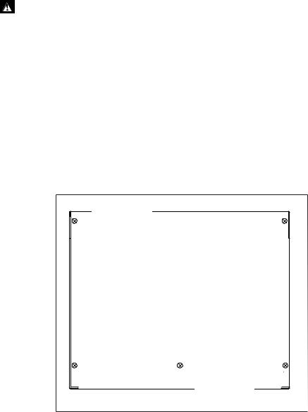
3.Fit rubber feet, if supplied.
All models except the SwitchBlade x908 ship with rubber feet. They stop the switch from slipping and protect the surface from scratches. The x900-12XT/S switch has four feet. All other models have five feet. Using the screws provided, screw the rubber feet in the holes on the underside of the switch. Use the following diagram to locate the screw holes. For the x900-12XT/S, use positions 1, 2, 3, and 5.
Front of Switch
1 |
2 |
Underside
3 |
4 |
5 |
Rear of Switch
 Screw holes for rubber feet
4.Place the switch in the desired location for operation.
8

Installation and Safety Guide
In a 19-inch rack
1.Ensure the rack has sufficient space for the switch and its cables. For the switch’s requirements, see “Selecting a Site” on page 6.
2.Install cage nuts at the front of the rack so they are ready for the rackmount screws in the following steps.
3.Unpack the switch.
It may be helpful to temporarily remove any PSU or FOM so that the switch is lighter and easier to manipulate during installation. For more information, see the Removable Power Supply and Fan Installation Guide.
4.Screw one bracket to each side of the switch using the M4 screws provided.
On the x900-12XT switch, you can use the alternative set of holes on the rack mount bracket to mount the switch further back in the rack.
For NEBS ensure the rack and hardware have been pre-treated, as described in “Preparation for NEBS” on page 7.
Fitting a bracket on an x900-12XT/S switch
9

x900 Series Switch and SwitchBlade® x908
Fitting a bracket on a SwitchBlade x908 switch
Fitting a bracket on all other x900 Series switches
5.Mount the switch into the rack from the front, and tighten the rack-mount screws.
Two people are required at this point. One person can lift the switch into the rack and attach it to the front rails while the second person safely supports it from the rear.
10

Installation and Safety Guide
Applying Power to the Switch
Power supply bays are in the rear of the switch. Depending on the model, the switch may have a PSU, FOM, or blanking plate over a power supply bay.
Connecting an AC power supply
Follow these instructions to connect one of the following to an AC power supply:
■an AT-PWR01, AT-PWR02, or AT-PWR05 AC PSU
■an x900-12XT/S switch
Warning The AT-PWR01 AC PSU has a fuse rating of 250V, 5A for FH101 and FH102.
Warning The AT-PWR01 AC PSU has double pole/neutral fusing. Electric shock is possible since there are dual primary fuses, one on the phase circuit and one on the neutral circuit. If the neutral opens, the phase may still be live.
Warning When x900-24 units are connected with VCS stacking cables (XEM- STK-CBL) ensure that all the PSUs are appropriately grounded. This is to avoid large circulating ground currents that could damage the stacking cables. To achieve this ensure that:
■AT-PWR01 AC is grounded by the 3-pin AC power connector
■All grounding points are at the same ground level. That is, all power connectors share a common power distribution unit.
Warning For x900-24 models, when using an AT-PWR01 AC power supply and an AT-PWR01 DC power supply in the same switch, then the ground-terminal of the DC power connector must be connected to the same ground as the AC ground pin of the AC power connector.
If this is not possible, then you must ground the AT-PWR01 AC only, and leave the AT-PWR01 DC power connector ungrounded. In this case, as a safety precaution, ensure that the rack is also grounded.
Warning For SwitchBlade x908 AC models the grounding stud on the rear of the unit is for supplemental grounding only. The system must be supplied by a grounded 3 wire AC source through the power supply cord.
Warning When SBx908 devices are connected with VCS stacking cables (either HS-STK-CBL or XEM-STK-CBL), each individual stack member chassis must be additionally grounded by using the rear grounding-terminal on each device. In order to avoid large circulating ground currents, the wires of each grounding cable must be 18AWG or thicker.
11

x900 Series Switch and SwitchBlade® x908
1. Plug the AC power cord that is provided into the power inlet on the PSU.
2.Connect the power cord to the main power source.
3.On the AT-PWR05, set the Run/Standby switch to Run.
4.Check that the PSU LED on the front panel of the switch is lit green. If the LED does not light, refer to the Hardware Reference for troubleshooting information.
Connecting a DC power supply
Follow these instructions to connect an AT-PWR01 or an AT-PWR05 DC PSU to a DC power supply. Only trained and qualified personnel should connect a DC power supply.
For centralised DC power connection, the switch should be installed in restricted access areas only, such as dedicated equipment rooms or equipment closets, in accordance with Articles 110-16, 110-17, and 110-18 of the National Electrical Code, ANSI/NFPA 70.
Warning In order to avoid damaging the PSU, make sure that the PSU terminals are wired to the correct polarity.
Warning When x900-24 units are connected with VCS stacking cables (XEM- STK-CBL) ensure that all the PSUs are appropriately grounded. This is to avoid large circulating ground currents that could damage the stacking cables. To achieve this ensure that:
•AT-PWR01 DC is grounded at the GND terminal. In order to avoid large circulating ground currents, the wires of each grounding cable must be 18AWG or thicker.
•All grounding points are at the same ground level. That is, all power connectors share a common power distribution unit.
Warning When mounting one or two AT-PWR01 DC PSUs to a grounded rack, ensure that the ground level of the rack and the DC power connector are the same.
Warning For x900-24 models, when using an AT-PWR01 AC power supply and an AT-PWR01 DC power supply in the same switch, then the ground-terminal of the DC power connector must be connected to the same ground as the AC ground pin of the AC power connector.
If this is not possible, then you must ground the AT-PWR01 AC only, and leave the AT-PWR01 DC power connector ungrounded. In this case, as a safety precaution, ensure that the rack is also grounded.
12

Installation and Safety Guide
Warning When SBx908 devices are connected with VCS stacking cables (either HS-STK-CBL or XEM-STK-CBL), each individual stack member chassis must be additionally grounded by using the rear grounding-terminal on each device. In order to avoid large circulating ground currents, the wires of each grounding cable must be 18AWG or thicker.
PWR01 PWR01 DC
DC
Power supply specifications:
■functional range 40 to 60V, 48V nominal
■supports either positive grounded or negative grounded operation
■a 15Amp certified/listed circuit breaker is required for circuit protection
Supply cable specifications:
■tray cable should be UL listed Type TC tray cable (or equivalent)
■three-core cable is required
■minimum core size: 3.3mm2 (12 AWG) high strand count copper wire
■minimum cable rating: 600V, 90 degrees C
Warning Disconnect the power supply cable before starting this procedure.
1.Remove the transparent protective terminal cover.
2.Strip the supply cable wires to expose 7.5mm (0.31in.) of bare conductor. Terminate the wire with a nylon insulated solderless ring tongue terminal, JST FN5.5-5 or equivalent, using a crimp tool.
3.Connect the ground wire to the ground terminal. Use the diagram on the rear panel of the switch to identify terminals. Tighten the terminal to between 2.4 and 4.0 Nm (21.3 and 35.4 lbf in).
4.Connect the positive feed to the + (positive) terminal and the negative feed to the - (negative) terminal. Tighten the terminals to between 2.4 and
4.0Nm (21.3 and 35.4 lbf in).
Note that the DC return input terminal must be connected as an Isolated DC return (DC-I).
5.Ensure that there are no exposed cable strands.
6.Replace the cover. You must replace the transparent plastic terminal cover before continuing.
7.Secure the supply cable to the rack framework or a similar object to ensure that connections are isolated from any force applied to the cable.
13
x900 Series Switch and SwitchBlade® x908
8.Ensure that the circuit breaker is off for the supply circuit and the Run/ Standby switch on the PSU. Release the Run/Standby switch so that it is not pushed in (which is the Off position).
9.Connect the supply cable wires to the circuit breaker.
10.Turn on the PSU by pushing in the Run/Standby switch.
11.Confirm that the switch is receiving power.
Check that at least one of the PSU LEDs on the front panel of the switch is lit green. If no LEDs light, refer to the Hardware Reference for troubleshooting information.
14
Installation and Safety Guide
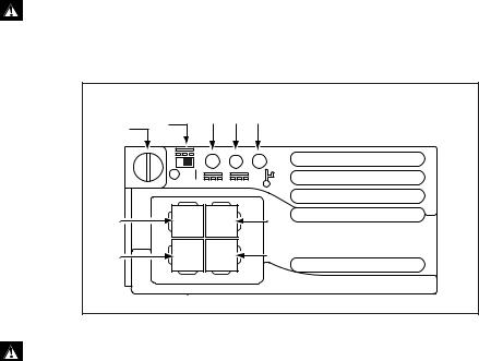
PWR05 PWR05 DC
DC
Power supply specifications:
■functional range 40 to 60V, 48V nominal
■supports either positive grounded or negative grounded operation
■a 30Amp certified/listed circuit breaker is required for circuit protection
Supply cable specifications:
■tray cable should be UL listed Type TC tray cable (or equivalent)
■three-core cable is required
■minimum core size: 3.3mm2 (12 AWG) high strand count copper wire
■minimum cable rating: 600V, 90 degrees C
Warning When mounting one or two AT-PWR05 DC PSUs to a grounded rack, ensure that the ground level of the rack and the DC power connector are the same.
|
|
DC |
DC |
|
|
|
RUN/STANDBY |
IN |
OUT |
FAULT |
|
|
LED |
LED |
LED |
||
CAPTIVE |
SWITCH |
||||
|
|
|
|||
|
|
|
|
||
SCREW |
|
|
|
|
|
N/C |
|
|
|
GREEN |
|
|
|
|
GND ) |
||
|
|
|
|
||
RED |
|
|
|
BLACK |
|
|
|
|
( - ) |
||
( + |
|
|
|
||
|
|
|
|
1.Ensure that the circuit breaker for the supply circuit and the Run/Standby switch on the PSU are off (slide to position O).
2.Plug the DC power cord into the power inlet on the PSU.
3.Connect the supply cable wires to the circuit breaker and switch the circuit breaker ON.
4.Turn on the PSU by sliding in the Run/Standby switch to position 1.
15
x900 Series Switch and SwitchBlade® x908
5.Confirm that the switch is receiving power.
Check that the PSU LED on the front panel of the switch corresponding to the PSU bay lights green. If the LED does not light green, check the Run/ Standby switch. See the Hardware Reference for more troubleshooting information.
16
Loading...