


AT-MC602
Table of contents
 Loading...
Extended
Ethernet
AT-MC601
AT-MC602
◆
Installation
and
User’s Guide
®
PN 613-50538-00 Rev B

Copyright © 2004 Allied Telesyn, Inc.
www.alliedtelesyn.com
All rights reserved. No part of this publication may be reproduced without prior written permission from Allied Telesyn, Inc.
Microsoft is a registered trademark of Microsoft Corporation, Netscape Navigator is a registered trademark of Netscape
Communications Corporation. All other product names, company names, logos or other designations mentioned herein are
trademarks or registered trademarks of their respective owners.
Allied Telesyn, Inc. reserves the right to make changes in specifications and other information contained in this document without
prior written notice. The information provided herein is subject to change without notice. In no event shall Allied Telesyn, Inc. be liable
for any incidental, special, indirect, or consequential damages whatsoever, including but not limited to lost profits, arising out of or
related to this manual or the information contained herein, even if Allied Telesyn, Inc. has been advised of, known, or should have
known, the possibility of such damages.

3
Electrical Safety and Emission
Statement
Standards: This product meets the following standards.
Warning: In a domestic environment this product may cause radio interference in which case the user may be required to take
adequate measures.
U.S. Federal Communications Commission
Declaration Of Conformity
Manufacture Name: Allied Telesyn, Inc. (www.alliedtelesyn.com)
Declares that the product: Extended Ethernet
Model Numbers: AT-MC601, AT-MC602
This product complies with FCC Part 15B, Class A Limits:
This device complies with part 15 of the FCC Rules. Operation is subject to the following two conditions: (1) This device must
not cause harmful interference, and (2) this device must accept any interference received, including interference that may
cause undesired operation.
Radiated Energy
Note: This equipment has been tested and found to comply with the limits for a Class A digital device pursuant to Part 15 of FCC
Rules. These limits are designed to provide reasonable protection against harmful interference in a residential installation. This
equipment generates, uses and can radiate radio frequency energy and, if not installed and used in accordance with
instructions, may cause harmful interference to radio or television reception, which can be determined by turning the
equipment off and on. The user is encouraged to try to correct the interference by one or more of the following measures:
- Reorient or relocate the receiving antenna.
- Increase the separation between the equipment and the receiver.
- Connect the equipment into an outlet on a circuit different from that to which the receiver is connected.
- Consult the dealer or an experienced radio/TV technician for help.
Changes and modifications not expressly approved by the manufacturer or registrant of this equipment can void your
authority to operate this equipment under Federal Communications Commission rules.
FCC Part 68 Product Identifier
This equipment complies with Part 68 if the FCC rules and the requirements adopted by the ACTA. On the bottom of the
equipment is a label that contains, among other information, a product identifier in the following format:
• US: A5TOT00BMC60X
If requested, this number must be provided to the telephone company.
Industry Canada
This equipment complies with Industry Canada CS03 Standard, Certificate Number: IC:336A-MC60X.
This Class A digital apparatus meets all requirements of the Canadian Interference-Causing Equipment Regulations.
Cet appareil numérique de la classe A respecte toutes les exigences du Règlement sur le matériel brouilleur du Canada.

AT-MC601 and AT-MC602 Installation and User’s Guide
4
RFI Emission EN55022 Class A, FCC Part 15 Class A, C-TICK
1
Immunity EN55024 2
E
lectrical Safety EN60950, UL60950, FCC Part 68 3
Important: Appendix C contains translated safety statements for installing this equipment. When you see the , go to Appendix
C for the translated safety statement in your language.
Wichtig: Anhang C enthält übersetzte Sicherheitshinweise für die Installation dieses Geräts. Wenn Sie
sehen, schlagen Sie in
Anhang C den übersetzten Sicherheitshinweis in Ihrer Sprache nach.
Vigtigt: Tillæg C indeholder oversatte sikkerhedsadvarsler, der vedrører installation af dette udstyr. Når De ser symbolet , skal
De slå op i tillæg C og finde de oversatte sikkerhedsadvarsler i Deres eget sprog.
Belangrijk: Appendix C bevat vertaalde veiligheidsopmerkingen voor het installeren van deze apparatuur. Wanneer u de
ziet,
raadpleeg Appendix C voor vertaalde veiligheidsinstructies in uw taal.
Important: L'annexe C contient les instructions de sécurité relatives à l'installation de cet équipement. Lorsque vous voyez le
symbole
, reportez-vous à l'annexe C pour consulter la traduction de ces instructions dans votre langue.
Tärkeää: Liite C sisältää tämän laitteen asentamiseen liittyvät käännetyt turvaohjeet. Kun näet
-symbolin, katso käännettyä
turvaohjetta liitteestä C.
Importante: l’Appendice C contiene avvisi di sicurezza tradotti per l’installazione di questa apparecchiatura. Il simbolo
, indica
di consultare l’Appendice C per l’avviso di sicurezza nella propria lingua.
Viktig: Tillegg C inneholder oversatt sikkerhetsinformasjon for installering av dette utstyret. Når du ser
, åpner du til Tillegg C
for å finne den oversatte sikkerhetsinformasjonen på ønsket språk.
Importante: O Anexo C contém advertências de segurança traduzidas para instalar este equipamento. Quando vir o símbolo
,
leia a advertência de segurança traduzida no seu idioma no Anexo C.
Importante: El Apéndice C contiene mensajes de seguridad traducidos para la instalación de este equipo. Cuando vea el símbolo
, vaya al Apéndice C para ver el mensaje de seguridad traducido a su idioma.
Obs! Bilaga C innehåller översatta säkerhetsmeddelanden avseende installationen av denna utrustning. När du ser
, skall du gå
till Bilaga C för att läsa det översatta säkerhetsmeddelandet på ditt språk.

5
Contents
Electrical Safety and Emission Statement ............................................................................................................................................... 3
Preface ......................................................................................................................................................................................................................7
How This Guide is Organized ............................................................................................................................................................................. 7
Document Conventions ...................................................................................................................................................................................... 8
Contacting Allied Telesyn Technical Support ..............................................................................................................................................9
Online Support ............................................................................................................................................................................................... 9
E-mail and Telephone Support ................................................................................................................................................................ 9
Returning Products ....................................................................................................................................................................................... 9
For Sales or Corporate Information ........................................................................................................................................................ 9
Obtaining Management Software Updates ........................................................................................................................................ 9
Chapter 1
Product Description .........................................................................................................................................................................................10
Summary of Features ..........................................................................................................................................................................................10
Overview .................................................................................................................................................................................................................11
Location of Components ...................................................................................................................................................................................12
Hardware Features ..............................................................................................................................................................................................13
VDSL Line Port .............................................................................................................................................................................................. 13
PSTN Port........................................................................................................................................................................................................ 14
10/100 Mbps Twisted Pair Ethernet Port ............................................................................................................................................ 14
Status LEDs .................................................................................................................................................................................................... 16
MGMT Port ..................................................................................................................................................................................................... 17
Management Cable .................................................................................................................................................................................... 17
AC Power Supply Input Port .............................................................................................................................................................................18
External AC/DC Power Adapter.............................................................................................................................................................. 18
Software Features ................................................................................................................................................................................................19
Chapter 2
Installation ............................................................................................................................................................................................................20
Installation Safety Precautions ........................................................................................................................................................................21
Additional Compliance Warning Statements ................................................................................................................................... 22
Selecting a Site for the Network Extender ..................................................................................................................................................23
Cables Not Included ............................................................................................................................................................................................24
Unpacking the Network Extender .................................................................................................................................................................25
Installing the AT-MC601 Subscriber Unit ....................................................................................................................................................26
Using the Subscriber Unit on a Desktop............................................................................................................................................. 26
Wall-Mounting the Subscriber Unit...................................................................................................................................................... 27
Cabling the Subscriber Unit..................................................................................................................................................................... 28
Powering On the Subscriber Unit.......................................................................................................................................................... 29

AT-MC601 and AT-MC602 Installation and User’s Guide
6
Installing the AT-MC602 Provider Unit .........................................................................................................................................................30
Cabling the Provider Unit......................................................................................................................................................................... 32
Powering On the Provider Unit.............................................................................................................................................................. 33
Warranty Registration .........................................................................................................................................................................................34
Chapter 3
Configuration ......................................................................................................................................................................................................35
Starting a Configuration Session ....................................................................................................................................................................36
Downloading Software Updates ........................................................................................................................................................... 36
Cabling Preparations.................................................................................................................................................................................. 36
Opening the Configuration Software .................................................................................................................................................. 37
Configuring the Provider Unit .........................................................................................................................................................................38
Configuration................................................................................................................................................................................................ 38
VDSL Status.................................................................................................................................................................................................... 40
Ethernet Status............................................................................................................................................................................................. 42
Configuring the Subscriber Unit .....................................................................................................................................................................45
Chapter 4
Troubleshooting ................................................................................................................................................................................................47
LEDs.................................................................................................................................................................................................................. 47
Error Messages ............................................................................................................................................................................................. 48
Appendix A
Default Configuration Settings ..................................................................................................................................................................51
Appendix B
Technical Specifications .................................................................................................................................................................................52
Physical Specifications .......................................................................................................................................................................................52
Environmental Specifications ..........................................................................................................................................................................52
Power Specifications ...........................................................................................................................................................................................52
Safety and Electromagnetic Compatibility Certifications .....................................................................................................................53
Appendix C
Translated Electrical Safety and Emission Information ..................................................................................................................54

7
Preface
This guide contains instructions on how to install and configure the
AT-MC601 and AT-MC602 Extended Ethernet units.
How This Guide is Organized
This manual contains the following chapters and appendices:
Chapter 1, Product Description, describes the features and
components of the network extenders.
Chapter 2, Installation, contains installation instructions for each unit.
Chapter 3, Configuration, explains how to use the configuration
software. The AT-S57 software is used to configure the network
extenders.
Chapter 4, Troubleshooting, provides information on how to resolve
common problems that might occur with the network extenders.
Appendix A, Default Settings, lists the default software settings.
Appendix B, Technical Specifications, lists the technical specifications
for the network extenders.
Appendix C, Translated Electrical Safety and Emission Information,
contains multi-language translations of the warnings and cautions in the
manual.

AT-MC601 and AT-MC602 Installation and User’s Guide
8
Document Conventions
This document uses the following conventions:
Note
Notes provide additional information.
Warning
Warnings inform you that performing or omitting a specific action
may result in bodily injury.
Caution
Cautions inform you that performing or omitting a specific action
may result in equipment damage or loss of data.

AT-MC601 and AT-MC602 Installation and User’s Guide
9
Contacting Allied Telesyn Technical Support
This section provides Allied Telesyn contact information for technical
support as well as sales or corporate information.
Online Support You can request technical support online by accessing the Allied Telesyn
Knowledge Base from the following web site:
http://kb.alliedtelesyn.com. You can use the Knowledge Base to
submit questions to our technical support staff and review answers to
previously asked questions.
E-mail and
Telephone
Support
For Technical Support via E-mail or telephone, refer to the Support &
Services section of the Allied Telesyn web site:
http://www.alliedtelesyn.com.
Returning
Products
Products for return or repair must first be assigned a Return Materials
Authorization (RMA) number. A product sent to Allied Telesyn without a
RMA number will be returned to the sender at the sender’s expense.
To obtain a RMA number, contact Allied Telesyn’s Technical Support at
our web site: http://www.alliedtelesyn.com
For Sales or
Corporate
Information
You can contact Allied Telesyn for sales or corporate information at our
web site: http://www.alliedtelesyn.com. To find the contact information
for your country, select Contact Us then Worldwide Contacts.
Obtaining
Management
Software
Updates
New releases of management software for our managed products can
be downloaded from either of the following Internet sites:
• Allied Telesyn web site: http://www.alliedtelesyn.com
• Allied Telesyn FTP server: ftp://ftp.alliedtelesyn.com
If you would prefer to download new software from the Allied Telesyn
FTP server from your workstation’s command prompt, you will need FTP
client software and you will be asked to log in to the server. Enter
‘anonymous’ as the user name and your email address for the password.

10
Chapter 1
Product Description
The AT-MC601, AT-MC602 Extended Ethernet products are designed to
transmit data at very high speeds over unshielded pairs of copper wires
using VDSL technology on your existing telephone line.
Summary of Features
❑ VDSL (Very high-bit-rate Digital Subscriber) Line port
❑ PSTN (Public Switched Telephone Network) port
❑ 10/100 Mbps Ethernet port with an RJ-45 connector
❑ Auto MDI/MDI-X
❑ Auto-Negotiation for speed and duplex mode (IEEE 803.3u-
compliant)
❑ Status LEDs
❑ Management port
❑ AT-S57 configuration software
❑ 12V DC external power supply input port
AT-MC601 and AT-MC602 Installation and User’s Guide
11
Overview
These devices can be used in multi-dwelling units (MDU), multi-tenant
buildings (MTU), and in the hospitality industry, such as airports, hotels,
and convention centers.
These units are sold in pairs with the AT-MC601 functioning as the
subscriber and the AT-MC602 functioning as the provider. In an MDU,
such as a university dormitory, the subscriber unit would be installed in
each room and connected to a provider unit through the telephone
outlet. Each AT-MC602 or provider unit would be located in the building
wiring closet.
The AT-MC601 Extended Ethernet unit can be used as a desktop or
wallmount device while the AT-MC602 unit must be installed in an
AT-MCR12 rackmount chassis. Refer to ”Installing the AT-MC602 Provider
Unit” on page 30" for installation details. These units are easy to install.
They can be configured and managed through the MGMT port using the
software provided on the installation CD.
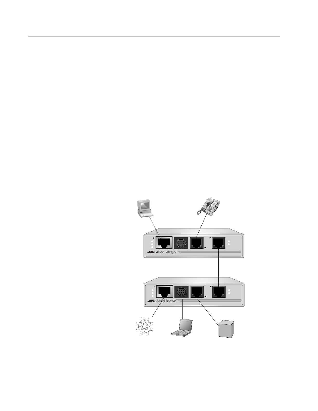
When both the AT-MC601 Subscriber and the AT-MC602 Provider have
been installed, the network extender system topology shown in Figure 1
is complete.
Figure 1 Network Extender System Topology
LINE
10BaseT/
100BaseTX
PSTN
LINK
ACT
PWR
ERR
LINK
MGMT
AT-MC601
VDSL EXTENDED ETHERNET
VDSL Line through
LINE
10BaseT/
100BaseTX
PSTN
LINK
ACT
PWR
ERR
LINK
MGMT
AT-MC602
VDSL EXTENDED ETHERNET
wall/interior phone line
AT-MC601
Subscriber
Unit
AT-MC602
Provider
Unit
Computer’s
Telephone
Ethernet Port
Internet
Service
Provider
Laptop
Telco
PBX
Line
AT-MC601 and AT-MC602 Installation and User’s Guide
12
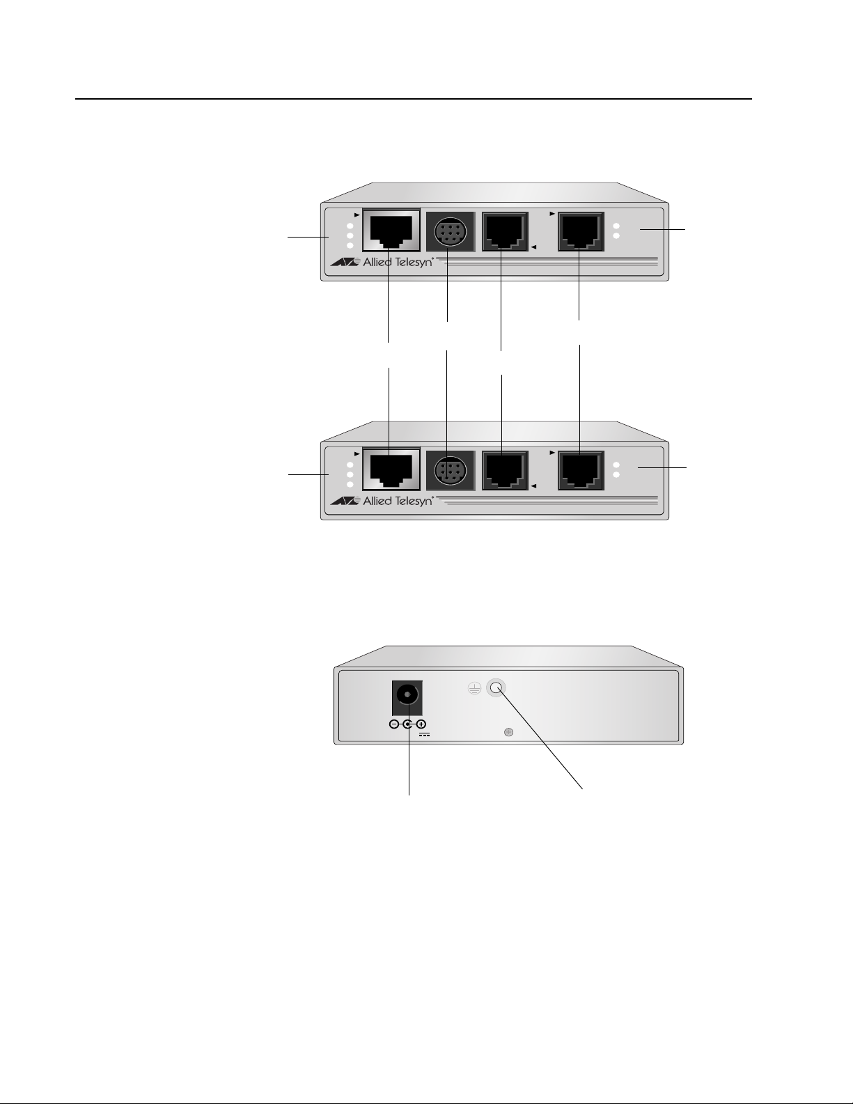
Location of Components
Figure 2 illustrates the front panels of the AT-MC601 and AT-MC602
network extenders.
Figure 2 Front Panels
Figure 3 illustrates the rear panel of the AT-MC601 and AT-MC602
network extenders.
Figure 3 Rear Panel
LINE
10BaseT/
100BaseTX
PSTN
LINK
ACT
PWR
ERR
LINK
MGMT
AT-MC601
VDSL EXTENDED ETHERNET
Ethernet Port
Management Port
PSTN Port
VDSL Line
LEDs
VDSL Line Port
LINE
10BaseT/
100BaseTX
PSTN
LINK
ACT
PWR
ERR
LINK
MGMT
AT-MC602
VDSL EXTENDED ETHERNET
VDSL Line
LEDs
Ethernet
Status
LEDs
Ethernet
Status
LEDs
12 VD C
DC Power Supply Port
M4 Self-Clinching Nut

AT-MC601 and AT-MC602 Installation and User’s Guide
13
Hardware Features
The following sections describe these hardware features of the
AT-MC601 and AT-MC602 network extenders:
❑ VDSL Line port
❑ PSTN port
❑ 10/100 Mbps twisted pair Ethernet port
❑ Status LEDs
❑ Management port
❑ Management cable
❑ 12V DC power supply input port
❑ External AC/DC power adapter
Note
The AT-MC602 unit can only be installed in an AT-MCR12 chassis.
VDSL Line Port The VDSL Line port allows you to connect the AT-MC601 Subscriber unit
to a telephone jack (wall outlet) and the AT-MC602 Provider unit to the
inside phone line at the wiring closet. The two units need to be within
1,200 meters of each other in order for the port to operate properly. The
port transmits voice data at a frequency of 8-10 KHz and Ethernet data at
frequencies of 300 KHz to 8 MHz. This port features an RJ-11 connector.
Table 1 lists the RJ-11 port pinouts and their assignments.
Table 1 VDSL - RJ-11 Port Pinouts
Pin Assignment
1 pass-through 6
2 pass-through 5
3 Ethernet and phone ring
4 Ethernet and phone tip
5 pass-through 2
6 pass-through 1

AT-MC601 and AT-MC602 Installation and User’s Guide
14
PSTN Port The PSTN port allows you to connect the AT-MC601 Subscriber unit to a
telephone and the AT-MC602 Provider unit to the outside telco box. This
port features an RJ-11 connector.
Table 2 lists the RJ-11 port pinouts and their assignments.
10/100 Mbps
Twisted Pair
Ethernet Port
The AT-MC601 and AT-MC602 network extenders each have one twisted
pair Ethernet port. The twisted pair ports feature RJ-45 connectors with a
maximum operating distance of 100 meters (328 feet). For the port
pinout details, refer to ”RJ-45 Port Pinouts” on page 15.
Type of Cabling.The 10/100Base-TX twisted pair port on the AT-
MC601 and AT-MC602 network extenders are designed to operate with
Category 3 or better unshielded twisted pair cables. For 10 Mbps
operation on the twisted pair ports, Category 3 or better 100 ohm
unshielded twisted pair cabling is required. For 100 Mbps operation on
the twisted pair ports, Category 5 and Enhanced Category 5 (5E) 100
ohm unshielded twisted pair cabling is recommended.
Auto MDI/MDI-X.An RJ-45 twisted pair port on a 10/100 Mbps
Ethernet network device can have one of two possible wiring
configurations: MDI or MDI-X. The RJ-45 port on a PC, router, or bridge is
typically wired as MDI, while the twisted pair port on a switch or hub is
usually MDI-X.
The AT-MC601 and AT-MC602 network extenders feature automatic
MDI/MDI-X. Each port automatically determines the configuration of the
port on the device to which it is connected and then configures itself
appropriately. For example, if a port on a network extender is connected
to a port on a bridge, which is typically wired as MDI, the port on the
network extender automatically configures itself as MDI-X. This feature
allows you to use either straight-through or crossover cables when
connecting devices to the network extender.
Table 2 PSTN - RJ-11 Port Pinout
Pin Assignment
1 pass-through 1/6
2 pass-through 2/5
3 Ethernet and phone ring
4 Ethernet and phone tip
5 pass-through 5/2
6 pass-through 6/1
AT-MC601 and AT-MC602 Installation and User’s Guide
15
Auto-Negotiation.The network extenders Auto-Negotiate the
speed and duplex mode of the Ethernet link, so that the link comes up in
the highest performance configuration supported by both ends.
Half- and Full-duplex Mode.Duplex mode refers to the way an
end-node sends and receives data on the network. An end-node can
operate in either half- or full-duplex mode, depending on its capabilities.
An end-node that is operating in half-duplex mode can either send data
or receive data, but it cannot do both at the same time. An end-node
that is operating in full-duplex mode can send and receive data
simultaneously. The best network performance is achieved when an
end-node can operate at full-duplex, since the end-node is able to send
and receive data simultaneously.
The AT-MC601 and AT-MC602 network extenders can operate in either
half- or full-duplex mode. The network extender can operate with end-
nodes capable of either half-duplex, full-duplex, or that can Auto-
Negotiate the duplex mode. However, it is important to remember that
the two end-nodes connected to the ports on the network extenders
must be able to operate in the same duplex mode.
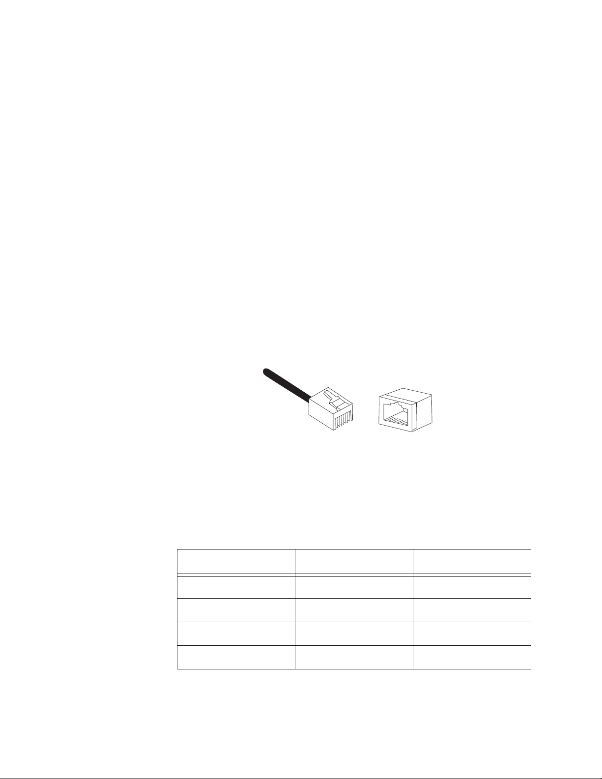
RJ-45 Port Pinouts.Figure 4 illustrates the pin assignments of an
RJ-45 connector and port.
Figure 4 RJ-45 Connector and Port Pin Assignments
Table 3 lists the RJ-45 10Base-T/100Base-TX connector pins and their
signals when the port is operating in either MDI or MDI-X configuration.
Table 3 RJ-45 Port Pinouts
Pin MDI Signal MDI-X Signal
1TX+RX+
2TX-RX-
3RX+TX+
6RX-TX-
8
8
1
1

AT-MC601 and AT-MC602 Installation and User’s Guide
16
Status LEDs The AT-MC601 and AT-MC602 network extenders feature the following
status LEDs:
❑ Power
❑ Ethernet: link and activity
❑ VDSL Line: link and error
Table 4 defines the LEDs for the AT-MC601 and AT-MC602 network
extenders.
Table 4 Status LEDs
LED Color Description
PWR Green Power is applied to the unit.
10/100Base-TX Port
LINK Green A link has been established on the port.
ACT Green Data is being received on the ports.
LINE Port
ERR Green An error has been detected on the port.
LINK Green A link has been established on the port.
AT-MC601 and AT-MC602 Installation and User’s Guide
17
MGMT Port The management port features a 8-pin DIN connector for connecting
the network extenders to your laptop or PC-compatible computer for
configuration using the provided management cable.
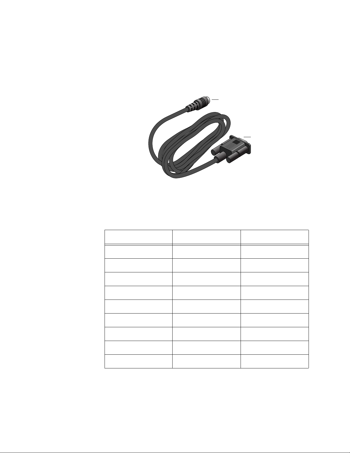
Management
Cable
The management cable included with the AT-MC602 Provider unit
features a 9-pin RS-232 connector to attach to your computer and an
8-pin DIN connector to attach to the network extender.
Figure 5 Management Cable
Table 5 lists the management cable connector pins and their signals.
Table 5 Management Cable Pinouts
RS-232 Pin DIN Pin Signal
1 1 Not Used
22TXD
38RXD
45DSR
56GND
63DTR
7 4 CTS
87RTS
9 (N/A) Not Used
8-pin DIN connector
9-pin RS-232
connector

AT-MC601 and AT-MC602 Installation and User’s Guide
18
AC Power Supply Input Port
The network extender has a single DC power supply socket on the back
panel. The unit does not have a power switch. To turn the network
extender ON or OFF, you connect or disconnect the power cord.
External AC/DC
Power Adapter
An external AC/DC power adapter is included with the network extender
for desktop or wall-mount operation. The power adapter supplies 12V
DC to the network extender. Allied Telesyn supplies an approved safety
compliant AC power adapter specifically designed for each region the
network extender is sold. Each type of power adapter has an
unregulated output of 12V DC at 1A.
Note
The power adapter mentioned above is not required to be used with
the AT-MC602 Provider unit because the AT-MC602 Provider unit
can only be installed in the AT-MCR12 chassis

AT-MC601 and AT-MC602 Installation and User’s Guide
19
Software Features
The AT-S57 software used to configure the AT-MC601 and AT-MC602
network extenders has the following features:
❑ Determine the VDSL link status
❑ Set the upstream and downstream data transfer rates
❑ Monitor the status of the VDSL parameters on both the local and
remote units
❑ Monitor the status of the Ethernet parameters on both the local
and remote units
❑ Link recovery
Note
The features listed here are further described in ”Configuration” on
page 35.

20
Chapter 2
Installation
This chapter contains the installation procedures for the network
extenders. The installation process is described in the following sections:
❑ Installation Safety Precautions
❑ Selecting a Site for the Network Extender
❑ Required Cables
❑ Unpacking the Network Extender
❑ Installing the AT-MC601 Subscriber Unit
❑ Installing the AT-MC602 Provider Unit
❑ Warranty Registration
Loading...