


AT-FH824U-SW
Table of contents
 Loading...
AT-FH812u
AT-FH824u
AT-FH812u-SW
AT-FH824u-SW
Fast Ethernet 10/100 Hubs
Version 2
Installation Guide
PN 613-10753-00 Rev G

Copyright 2000 Allied Telesyn International, Corp.
960 Stewart Drive Suite B, Sunnyvale CA 94085 USA
All rights reserved. No part of this publication may be reproduced without prior written permission from Allied Telesyn
International, Corp.
Ethernet is a registered trademark of Xerox Corporation. All other product names, company names, logos or other designations
mentioned herein are trademarks or registered trademarks of their respective owners.
Allied Telesyn International, Corp. reserves the right to make changes in specifications and other information contained in this
document without prior written notice. The information provided herein is subject to change without notice. In no event shall Allied
Telesyn International, Corp. be liable for any incidental, special, indirect, or consequential damages whatsoever, including but not
limited to lost profits, arising out of or related to this manual or the information contained herein, even if Allied Telesyn
International, Corp. has been advised of, known, or should have known, the possibility of such damages.

Agency Compliance
EMI Certification
FCC Class A (USA)
Industry Canada
Class A
European EMC
Compliance
Warning: This equipment generates, uses, and can radiate radio
frequency energy and, if not installed and used in accordance with the
instruction manual, may cause interference to radio communications. It
has been tested and found to comply with the limits for a Class A digital
device pursuant to Subpart B of Part 15 of FCC Rules, which are designed
to provide reasonable protection against such interference when operated
in a commercial environment. Operation of this equipment in a
residential area is likely to cause interference, in which case the user, at
his own expense, will be required to take whatever measures are required
to correct the interference.
You may use shielded (STP) or unshielded twisted-pair (UTP) for RJ-45
connections - Category 3 or greater for 10 Mbps connections, and Category
5 for 100 Mbps connections.
This Class A digital apparatus meets all requirements of the Canadian
Interference-Causing Equipment Regulations.
Cet appareil numérique de la classe A respecte toutes les exigences du
Règlement sur le matériel brouilleur du Canada.
CE Mark Declaration of Conformance for EMI and Safety (EEC)
This is to certify that this product complies with ISO/IEC Guide 22 and
EN45014.
iii

Agency Compliance
Safety Compliance
It conforms to the following specifications:
!
Emissions: EN55022 (1988)/CISPR-22 (1985) class A
!
Immunity: EN50082-1
!
EN60555-2 (1995) class A
!
EN60555-3
Warning
Do not plug a phone jack connector in the RJ-45 port. This may damage
this device.
Warning
Before making connections, make sure you have the correct Cord Set.
Check it (read the label on the cable) against the following specification
list.
Voltage Cord Set Specifications
120 Volts UL Listed/CSA Certified Cord Set
Minimum 18 AWG; type SVT or SJT three conductor cord
Maximum length of 15 feet
Parallel blade, grounding type attachment plug rated 15A, 125V
240 Volts
(North America)
230 Volts
(Europe only)
UL Listed/CSA Certified Cord Set
Minimum 18 AWG; type SVT or SJT three conductor cord
Maximum length of 15 feet
Cord Set with H05VV-F cord having three conductors with
mimumum diameter of 0.75 mm
IEC-320 receptacle; male plug rated 10A, 250V
2
iv

Table of Contents
Agency Compliance
Welcome to Allied Telesyn
Where to Find Web-based Guides...................................................................................................................................vii
Documentation Conventions ................................................................................................................................ ........... vii
Contacting Allied Telesyn................................................................................................................................ ...............viii
Online Support................................................................................................................................ .........................viii
Technical Support Telephone and Fax Numbers...................................................................................................viii
Technical Support E-mail Addresses...................................................................................................................... viii
Returning Products................................................................................................................................ .................... ix
FTP Server ................................................................................................................................ ................................. ix
For Sales or Corporate Information.......................................................................................................................... ix
Tell Us What You Think................................................................................................................................ ............ ix
Chapter 1
Introduction
Chapter 2
Installation
Package Contents ................................................................................................................................ ....................... 3
Pre-Installation Requirements ................................................................................................................................ .. 3
Stacking Hubs on a Flat Surface ............................................................................................................................... 4
Rack-Mounting the Hubs ................................................................................................................................ ........... 4
Connecting the Hub System................................................................................................................................ ....... 4
Making a Connection via an MDI-X Station Port..................................................................................................... 5
Connecting to the Stack's Backplane......................................................................................................................... 5
Making a Connection via the MDI Daisy-Chain Port............................................................................................... 6
Using an Optional Module ......................................................................................................................................... 9
Installing an Optional Module................................................................................................................................... 9
Using the Agent Module (AT-FH805u).................................................................................................................... 10
Using the Switch Module (AT-FH806u) .................................................................................................................. 10
Using the 100Base-FX Module (AT-FH807u) ......................................................................................................... 11
Using the 100Base-TX Module (AT-FH808u) ......................................................................................................... 11
Powering ON the Hub ................................................................................................................................ .............. 12
Verifying Port Status................................................................................................................................................ 13
Verifying System Operation................................................................................................................................ ..... 14
.................................................................................................................................................................... 1
................................................................................................................................ ...................................... 3
................................................................................................................................ ......................iii
................................................................................................................................ .........vii
v

Table of Contents
Chapter 3
Troubleshooting
................................................................................................................................ ........................... 15
Diagnosing Hub LEDs................................................................................................................................ .............. 15
Power and Cooling Problems.................................................................................................................................... 15
Installation Verification ................................................................................................................................ ........... 16
Cabling Verification................................................................................................................................ .................. 16
Network Adapter Verification................................................................................................................................ .. 16
RJ-45 Port and Cable Assignments ......................................................................................................................... 16
Appendix A
Technical Specifications
............................................................................................................................................ 19
Product Specifications...................................................................................................................................................... 19
Base Unit ................................................................................................................................ .................................. 19
Network Criteria................................................................................................................................ ....................... 20
AT-FH805u Agent Module ................................................................................................................................ ....... 20
AT-FH806u Switch Module................................................................................................................................ ...... 21
AT-FH807u Uplink Module...................................................................................................................................... 21
AT-FH808u Uplink Module...................................................................................................................................... 21
Appendix B
Technical Support Fax Order
...................................................................................................................................23
Incident Summary ........................................................................................................................................................... 23
Appendix C
AT-FH800 Series Installation Guide Feedback
.................................................................................................... 25
vi

Welcome to Allied Telesyn
This guide contains instructions on how to install and configure a AT-FH800 Series
Fast Ethernet Hub.
Where to Find Web-based Guides
The Allied Telesyn web site at
way to access the most recent documentation and technical information for all of our
products. For product guides, you can go directly to the following web page:
www.alliedtelesyn.com/support/prd_libs.htm
Document Conventions
Through out this guide, you will notice several conventions that you should become
familiar with first before installing the product.
www.alliedtelesyn.com
Note
A note provides additional information.
Caution
A caution indicates that performing or omitting a specific action may result in
equipment damage or loss of data.
Warning
A warning indicates that performing or omitting a specific action may result in
bodily injury.
provides you with an easy
.
vii

Welcome to Allied Telesyn
Contacting Allied Telesyn Technical Support
There are several ways to contact Allied Telesyn technical support: online, telephone,
fax or e-mail.
Online Support
Telephone and Fax
Support
You can request technical support online by filling out the Online Technical Support
Form at
For Technical Support via fax, please fill out the “Technical Support Fax Order” on
page 23 and send it to the appropriate location listed below.
Americas
United States, Canada, Mexico,
Central America, South America
Tel: 1 (800) 428-4835, option 4
Fax: 1 (503) 639-3176
Asia
Singapore, Taiwan, Thailand, Malaysia,
Indonesia, Korea, Philippines, China,
India, Hong Kong
Tel: (+65) 381-5612
Fax: (+65) 383-3830
Australia
Tel: 1 (800) 000-880
Fax: (+61) 2-9438-4966
France
France, Belgium, Luxembourg,
The Netherlands, Middle East, Africa
Tel: (+33) 0-1-60-92-15-25
Fax: (+33) 0-1-69-28-37-49
www.alliedtelesyn.com/forms/support.htm
Germany
Germany, Switzerland, Austria, Eastern
Europe
Tel: (+49) 0130/83-56-66
Fax: (+49) 30-435-900-115
Italy
Italy, Spain, Portugal, Greece, Turkey,
l
Israe
Tel: (+39) 02-416047
Fax: (+39) 02-419282
Japan
Tel: (+81) 3-3443-5640
Fax: (+81) 3-3443-2443
United Kingdom
United Kingdom, Denmark, Norway,
Sweden, Finland
Tel: (+0044) 1235-442500
Fax: (+44) 1-235-442680
.
E-mail Support
viii
United States and Canada
TS1@alliedtelesyn.com
Latin America, Mexico, Puerto Rico, Caribbean, and Virgin Islands
latin_america@alliedtelesyn.com
United Kingdom, Sweden, Norway, Denmark, and Finland
support_europe@alliedtelesyn.com

AT-FH800 Series Installation Guide
Returning
Products
FTP Server
Products for return or repair must first be assigned a Return Materials Authorization
(RMA) number. A product sent to Allied Telesyn without a RMA number will be
returned to the sender at the sender’s expense.
To obtain an RMA number contact Allied Telesyn’s Technical Support at one of the
following locations:
North America
2205 Ringwood Ave
San Jose, CA 95131
Tel: 1-800-428-4835, option 4
Fax: 1-503-639-3716
Latin America, the Caribbean,
Virgin Islands
Tel: international code + 425-481-3852
Fax: international code + 425-483-9458
If you know the name of a specific driver that you need for an Allied Telesyn device,
you can download the software by connecting directly to our FTP server at:
ftp://gateway.centre.com
At login, enter ‘anonymous’. Enter your e-mail address for the password as requested
by the server at login.
.
European Customer Support Centre
10/11 Bridgemead Close
Westmead Industrial Estate
Swindon, Wiltshire SN5 7YT
England
Tel: +44-1793-501401
Fax: +44-1793-431099
Mexico and Puerto Rico
Tel: 1-800-424-5012, ext 3852 or
1-800-424-4284, ext 385
Mexico only: 95-800-424-5012, ext 3852
Fax: international code + 425-489-9191
2
For Sales or
Corporate
Information
Tell Us What You
Think
Allied Telesyn International, Corp.
19800 North Creek Parkway, Suite 200
Bothell, WA 98011
Tel: 1 (425) 487-8880
Fax: 1 (425) 489-9191
If you have any comments or suggestions on how we might improve this or other Allied
Telesyn documents, you can fill out the “AT-FH800 Series Installation Guide
Feedback” on page 25 and return the form to us at the address or fax number provide.
You can provide feedback online by filling out the Send Us Feedback Form at
www.alliedtelesyn.com/forms/feedback.htm
Allied Telesyn International, Corp.
960 Stewart Drive, Suite B
Sunnyvale, CA 94085
Tel: 1 (800) 424-4284 (USA and Canada)
Fax: 1 (408) 736-0100
.
ix

Chapter 1
Introduction
The AT-FH800 Series Fast Ethernet Hubs include the following models:
!
AT-FH812u
!
AT-FH824u
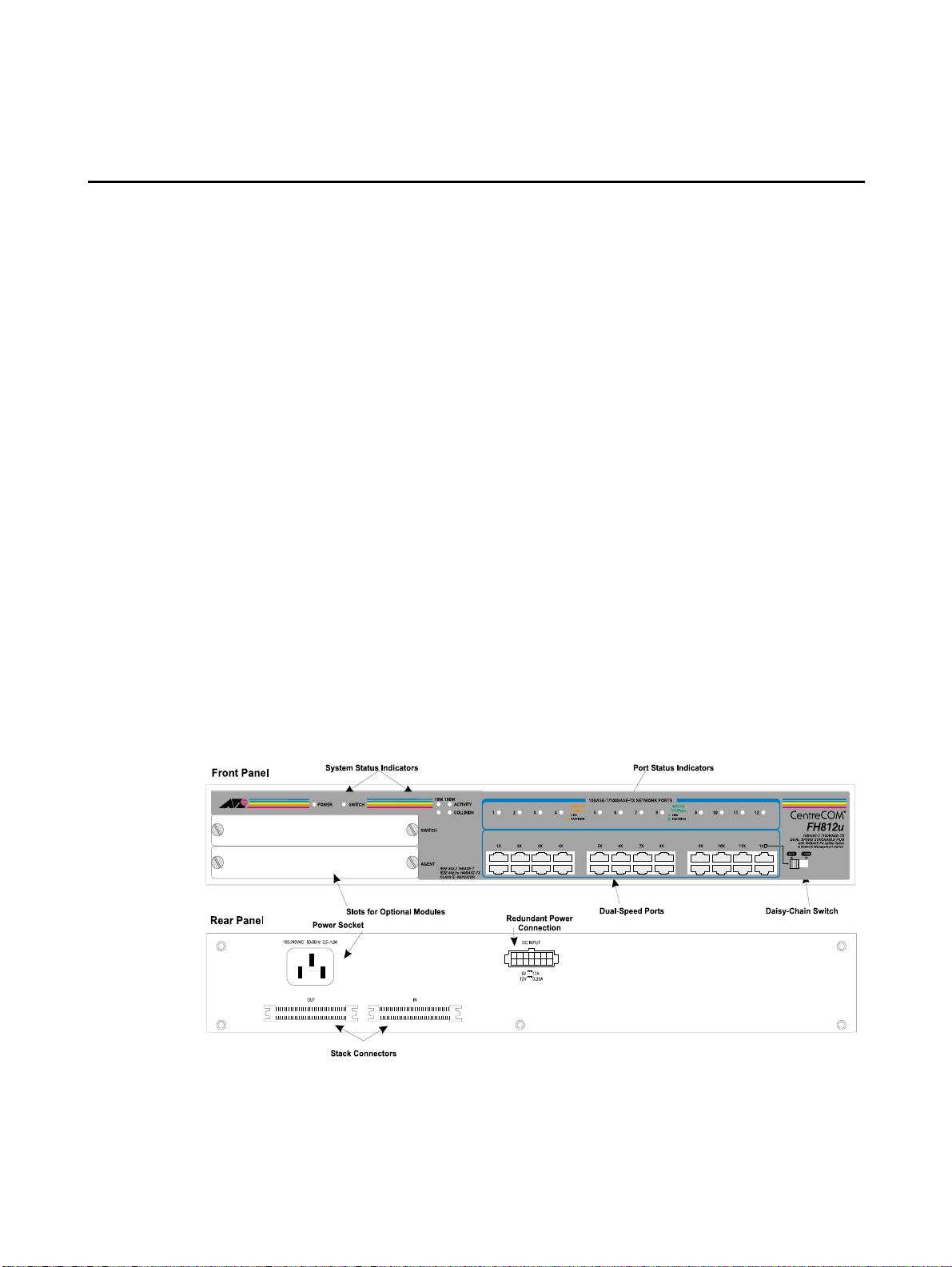
The AT-FH812u (shown in Figure 1) and AT-FH824u are manageable and
stackable Ethernet hubs with 12 or 24 dual-speed (RJ-45) ports. One slot is used
for an Optional Agent Module, and another slot for an Optional Switch Module.
The 12 and 24 port AT-FH812u-SW and AT-FH824u-SW are base unit with
optional switch modules installed. The AT-FH800-SW models are available in
North America only.
These dual-speed hubs provide the easiest method to upgrade your network to fast
Ethernet. It is not necessary to replace your existing network infrastructure. Just
add an Allied Telesyn dual-speed hub to your network and attach any 10 or 100
Mbps device to any port on the hubs. These hubs provide both the standard 10
Mbps bandwidth needed for common file transfers, and a larger channel with 100
Mbps of bandwidth that is essential for relieving serious network congestion,
running multimedia applications, or satisfying power users.
!
AT-FH812u-SW
!
AT-FH824u-SW
Figure 1
AT-FH812u Hub Front and Rear Panels
1
Loading...