


High-Density Layer 3 Stackable Gigabit Ethernet Switch
AT-9724TS
Installation and User’s Guide
PN D617/10032 Rev 1
Copyright. 2004 Allied Telesyn, Inc.
19800 North Creek Parkway, Suite 200, Bothell WA 98011, USA
All rights reserved. No part of this publication may be reproduced without prior written permission from Allied Telesyn,
Inc.All product names, company names, logos or other designations mentioned herein are trademarks or registered trademarks of their respective owners.Allied Telesyn, Inc. reserves the right to make changes in specifications and other information contained in this document without prior written notice.The information provided herein is subject to change
without notice. In no event shall Allied Telesyn Inc. be liable for any incidental, special, indirect, or consequential damages whatsoever, including but not limited to lost profits, arising out of or related to this manual or the information contained herein, even if Allied Telesyn, Inc. has been advised of, known, or should have known, the possibility of such damages.

Electrical Safety and Emission Statement
Standards:This product meets the following standards.
CE Marking Warning: This is a Class A product. In a domestic environment this product may cause radio interference in which case the user may be required to take adequate measures.
Important: Appendix B contains translated safety statements for installing this equipment.When you see the go to Appendix A for the translated safety statement in your language.
Wichtig: Anhang B enthält übersetzte Sicherheitshinweise für die Installation dieses Geräts.Wenn Sie sehen, schlagen Sie in Anhang A den übersetzten Sicherheitshinweis in Ihrer Sprache nach.
Vigtigt: Tillæg B indeholder oversatte sikkerhedsadvarsler, der vedrører installation af dette udstyr. Når De ser symbolet, skal De slå op i tillæg A og finde de oversatte sikkerhedsadvarsler i Deres eget sprog.
Belangrijk: Appendix B bevat vertaalde veiligheidsopmerkingen voor het installeren van deze apparatuur.Wanneer u de ziet, raadpleeg Appendix A voor vertaalde v eiligheidsinstructies in uw taal.
Important: L'annexe B contient les instructions de sécurité relatives à l'installation de cet équipement. Lorsque vous voyez le symbole , reportez-vous à l'annexe A pour consulter la traduction de ces instructions dans votre langue.
Tärkeää: Liite B sisältää tämän laitteen asentamiseen liittyvät käännetyt turvaohjeet. Kun näet -symbolin, katso käännettyä turvaohjetta liitteestä A.
Importante: l’Appendice B contiene avvisi di sicurezza tradotti per l’installazione di questa apparecchiatura. Il simbolo, indica di consultare l’Appendice A per l’avviso di sicurezza nella propria lingua.
Viktig: Tillegg B inneholder oversatt sikkerhetsinformasjon for installering av dette utstyret. Når du ser , åpner du til Tillegg A for å finne den oversatte sikkerhetsinformasjonen på ønsket språk.
Importante: O Anexo B contém advertências de segurança traduzidas para instalar este equipamento. Quando vir o símbolo , leia a advertência de segurança traduzida no seu idioma no Anexo A.
Importante: El Apéndice B contiene mensajes de seguridad traducidos para la instalación de este equipo. Cuando vea el símbolo , vaya al Apéndice A para ver el mensaje de seguridad traducido a su idioma.
Obs! Bilaga B innehåller översatta säkerhetsmeddelanden avseende installationen av denna utrustning. När du ser, skall du gå till Bilaga A för att läsa det översatta säkerhetsmeddelandet på ditt språk.
Allied Telesyn AT-9724TS High-Density Layer 3 Stackable Gigabit Ethernet Switch |
1 |

Table of Contents |
|
Electrical Safety and Emission Statement . . . . . . . . . . . . . . . . . . . . . . . . . . . . . . . . . . . . . . . . . . . . . . . . . . . . . . . . . . . . . . . . . . . . . . . . . . . . . . . . . . . . . . . . . . . . . . . . . . . . . . . . . . . . . . . |
. 1 |
Preface . . . . . . . . . . . . . . . . . . . . . . . . . . . . . . . . . . . . . . . . . . . . . . . . . . . . . . . . . . . . . . . . . . . . . . . . . . . . . . . . . . . . . . . . . . . . . . . . . . . . . . . . . . . . . . . . . . . . . . . . . . . . . . . . . . . . . . . . . . |
. 5 |
Purpose of This Guide . . . . . . . . . . . . . . . . . . . . . . . . . . . . . . . . . . . . . . . . . . . . . . . . . . . . . . . . . . . . . . . . . . . . . . . . . . . . . . . . . . . . . . . . . . . . . . . . . . . . . . . . . . . . . . . . . . . . . . . . . . . . . . . |
5 |
How This Guide is Organized . . . . . . . . . . . . . . . . . . . . . . . . . . . . . . . . . . . . . . . . . . . . . . . . . . . . . . . . . . . . . . . . . . . . . . . . . . . . . . . . . . . . . . . . . . . . . . . . . . . . . . . . . . . . . . . . . . . . . . . . . |
5 |
Document Conventions. . . . . . . . . . . . . . . . . . . . . . . . . . . . . . . . . . . . . . . . . . . . . . . . . . . . . . . . . . . . . . . . . . . . . . . . . . . . . . . . . . . . . . . . . . . . . . . . . . . . . . . . . . . . . . . . . . . . . . . . . . . . . . |
6 |
Where to Find Related Guides . . . . . . . . . . . . . . . . . . . . . . . . . . . . . . . . . . . . . . . . . . . . . . . . . . . . . . . . . . . . . . . . . . . . . . . . . . . . . . . . . . . . . . . . . . . . . . . . . . . . . . . . . . . . . . . . . . . . . . . . |
7 |
Contacting Allied Telesyn Technical Support . . . . . . . . . . . . . . . . . . . . . . . . . . . . . . . . . . . . . . . . . . . . . . . . . . . . . . . . . . . . . . . . . . . . . . . . . . . . . . . . . . . . . . . . . . . . . . . . . . . . . . . . . . . . . . |
7 |
Returning Products . . . . . . . . . . . . . . . . . . . . . . . . . . . . . . . . . . . . . . . . . . . . . . . . . . . . . . . . . . . . . . . . . . . . . . . . . . . . . . . . . . . . . . . . . . . . . . . . . . . . . . . . . . . . . . . . . . . . . . . . . . . . . . . . . |
8 |
FTP Server . . . . . . . . . . . . . . . . . . . . . . . . . . . . . . . . . . . . . . . . . . . . . . . . . . . . . . . . . . . . . . . . . . . . . . . . . . . . . . . . . . . . . . . . . . . . . . . . . . . . . . . . . . . . . . . . . . . . . . . . . . . . . . . . . . . . . . . . |
8 |
For Sales or Corporate Information . . . . . . . . . . . . . . . . . . . . . . . . . . . . . . . . . . . . . . . . . . . . . . . . . . . . . . . . . . . . . . . . . . . . . . . . . . . . . . . . . . . . . . . . . . . . . . . . . . . . . . . . . . . . . . . . . . . . |
8 |
Tell Us What You Think . . . . . . . . . . . . . . . . . . . . . . . . . . . . . . . . . . . . . . . . . . . . . . . . . . . . . . . . . . . . . . . . . . . . . . . . . . . . . . . . . . . . . . . . . . . . . . . . . . . . . . . . . . . . . . . . . . . . . . . . . . . . . . |
9 |
Introduction . . . . . . . . . . . . . . . . . . . . . . . . . . . . . . . . . . . . . . . . . . . . . . . . . . . . . . . . . . . . . . . . . . . . . . . . . . . . . . . . . . . . . . . . . . . . . . . . . . . . . . . . . . . . . . . . . . . . . . . . . . . . . . . . . . . . . |
10 |
Fast Ethernet . . . . . . . . . . . . . . . . . . . . . . . . . . . . . . . . . . . . . . . . . . . . . . . . . . . . . . . . . . . . . . . . . . . . . . . . . . . . . . . . . . . . . . . . . . . . . . . . . . . . . . . . . . . . . . . . . . . . . . . . . . . . . . . . . . . . . |
10 |
Gigabit Ethernet Technology . . . . . . . . . . . . . . . . . . . . . . . . . . . . . . . . . . . . . . . . . . . . . . . . . . . . . . . . . . . . . . . . . . . . . . . . . . . . . . . . . . . . . . . . . . . . . . . . . . . . . . . . . . . . . . . . . . . . . . . . . |
10 |
Switching Technology . . . . . . . . . . . . . . . . . . . . . . . . . . . . . . . . . . . . . . . . . . . . . . . . . . . . . . . . . . . . . . . . . . . . . . . . . . . . . . . . . . . . . . . . . . . . . . . . . . . . . . . . . . . . . . . . . . . . . . . . . . . . . . . |
10 |
Switch Description. . . . . . . . . . . . . . . . . . . . . . . . . . . . . . . . . . . . . . . . . . . . . . . . . . . . . . . . . . . . . . . . . . . . . . . . . . . . . . . . . . . . . . . . . . . . . . . . . . . . . . . . . . . . . . . . . . . . . . . . . . . . . . . . . |
11 |
Ports . . . . . . . . . . . . . . . . . . . . . . . . . . . . . . . . . . . . . . . . . . . . . . . . . . . . . . . . . . . . . . . . . . . . . . . . . . . . . . . . . . . . . . . . . . . . . . . . . . . . . . . . . . . . . . . . . . . . . . . . . . . . . . . . . . . . . . . . . . . . |
12 |
Installing the SFP ports. . . . . . . . . . . . . . . . . . . . . . . . . . . . . . . . . . . . . . . . . . . . . . . . . . . . . . . . . . . . . . . . . . . . . . . . . . . . . . . . . . . . . . . . . . . . . . . . . . . . . . . . . . . . . . . . . . . . . . . . . . . . . . |
12 |
Front-Panel Components. . . . . . . . . . . . . . . . . . . . . . . . . . . . . . . . . . . . . . . . . . . . . . . . . . . . . . . . . . . . . . . . . . . . . . . . . . . . . . . . . . . . . . . . . . . . . . . . . . . . . . . . . . . . . . . . . . . . . . . . . . . . |
12 |
LED Indicators . . . . . . . . . . . . . . . . . . . . . . . . . . . . . . . . . . . . . . . . . . . . . . . . . . . . . . . . . . . . . . . . . . . . . . . . . . . . . . . . . . . . . . . . . . . . . . . . . . . . . . . . . . . . . . . . . . . . . . . . . . . . . . . . . . . |
13 |
Rear Panel Components . . . . . . . . . . . . . . . . . . . . . . . . . . . . . . . . . . . . . . . . . . . . . . . . . . . . . . . . . . . . . . . . . . . . . . . . . . . . . . . . . . . . . . . . . . . . . . . . . . . . . . . . . . . . . . . . . . . . . . . . . . . . |
13 |
Side Panel Components . . . . . . . . . . . . . . . . . . . . . . . . . . . . . . . . . . . . . . . . . . . . . . . . . . . . . . . . . . . . . . . . . . . . . . . . . . . . . . . . . . . . . . . . . . . . . . . . . . . . . . . . . . . . . . . . . . . . . . . . . . . . . |
14 |
Installation . . . . . . . . . . . . . . . . . . . . . . . . . . . . . . . . . . . . . . . . . . . . . . . . . . . . . . . . . . . . . . . . . . . . . . . . . . . . . . . . . . . . . . . . . . . . . . . . . . . . . . . . . . . . . . . . . . . . . . . . . . . . . . . . . . . . . . . |
14 |
Package Contents. . . . . . . . . . . . . . . . . . . . . . . . . . . . . . . . . . . . . . . . . . . . . . . . . . . . . . . . . . . . . . . . . . . . . . . . . . . . . . . . . . . . . . . . . . . . . . . . . . . . . . . . . . . . . . . . . . . . . . . . . . . . . . . . . . |
14 |
Before You Connect to the Network. . . . . . . . . . . . . . . . . . . . . . . . . . . . . . . . . . . . . . . . . . . . . . . . . . . . . . . . . . . . . . . . . . . . . . . . . . . . . . . . . . . . . . . . . . . . . . . . . . . . . . . . . . . . . . . . . . . |
14 |
Installing the Switch Without the Rack . . . . . . . . . . . . . . . . . . . . . . . . . . . . . . . . . . . . . . . . . . . . . . . . . . . . . . . . . . . . . . . . . . . . . . . . . . . . . . . . . . . . . . . . . . . . . . . . . . . . . . . . . . . . . . . . . |
15 |
Installing the Switch in a Rack . . . . . . . . . . . . . . . . . . . . . . . . . . . . . . . . . . . . . . . . . . . . . . . . . . . . . . . . . . . . . . . . . . . . . . . . . . . . . . . . . . . . . . . . . . . . . . . . . . . . . . . . . . . . . . . . . . . . . . . . |
16 |
Mounting the Switch in a Standard 19" Rack . . . . . . . . . . . . . . . . . . . . . . . . . . . . . . . . . . . . . . . . . . . . . . . . . . . . . . . . . . . . . . . . . . . . . . . . . . . . . . . . . . . . . . . . . . . . . . . . . . . . . . . . . . . . |
16 |
Power On. . . . . . . . . . . . . . . . . . . . . . . . . . . . . . . . . . . . . . . . . . . . . . . . . . . . . . . . . . . . . . . . . . . . . . . . . . . . . . . . . . . . . . . . . . . . . . . . . . . . . . . . . . . . . . . . . . . . . . . . . . . . . . . . . . . . . . . . |
16 |
Power Failure . . . . . . . . . . . . . . . . . . . . . . . . . . . . . . . . . . . . . . . . . . . . . . . . . . . . . . . . . . . . . . . . . . . . . . . . . . . . . . . . . . . . . . . . . . . . . . . . . . . . . . . . . . . . . . . . . . . . . . . . . . . . . . . . . . . . . |
16 |
External Redundant Power System . . . . . . . . . . . . . . . . . . . . . . . . . . . . . . . . . . . . . . . . . . . . . . . . . . . . . . . . . . . . . . . . . . . . . . . . . . . . . . . . . . . . . . . . . . . . . . . . . . . . . . . . . . . . . . . . . . . . |
16 |
Connecting The Switch . . . . . . . . . . . . . . . . . . . . . . . . . . . . . . . . . . . . . . . . . . . . . . . . . . . . . . . . . . . . . . . . . . . . . . . . . . . . . . . . . . . . . . . . . . . . . . . . . . . . . . . . . . . . . . . . . . . . . . . . . . . . . |
17 |
Switch To End Node. . . . . . . . . . . . . . . . . . . . . . . . . . . . . . . . . . . . . . . . . . . . . . . . . . . . . . . . . . . . . . . . . . . . . . . . . . . . . . . . . . . . . . . . . . . . . . . . . . . . . . . . . . . . . . . . . . . . . . . . . . . . . . . . |
17 |
Switch to Hub or Switch . . . . . . . . . . . . . . . . . . . . . . . . . . . . . . . . . . . . . . . . . . . . . . . . . . . . . . . . . . . . . . . . . . . . . . . . . . . . . . . . . . . . . . . . . . . . . . . . . . . . . . . . . . . . . . . . . . . . . . . . . . . . |
17 |
Connecting To Network Backbone or Server. . . . . . . . . . . . . . . . . . . . . . . . . . . . . . . . . . . . . . . . . . . . . . . . . . . . . . . . . . . . . . . . . . . . . . . . . . . . . . . . . . . . . . . . . . . . . . . . . . . . . . . . . . . . |
18 |
Stacking and the AT-9724TS. . . . . . . . . . . . . . . . . . . . . . . . . . . . . . . . . . . . . . . . . . . . . . . . . . . . . . . . . . . . . . . . . . . . . . . . . . . . . . . . . . . . . . . . . . . . . . . . . . . . . . . . . . . . . . . . . . . . . . . . . . |
18 |
Stacking Limitations utilizing a Ring Topology . . . . . . . . . . . . . . . . . . . . . . . . . . . . . . . . . . . . . . . . . . . . . . . . . . . . . . . . . . . . . . . . . . . . . . . . . . . . . . . . . . . . . . . . . . . . . . . . . . . . . . . . . . . . |
19 |
Introduction To Switch Management . . . . . . . . . . . . . . . . . . . . . . . . . . . . . . . . . . . . . . . . . . . . . . . . . . . . . . . . . . . . . . . . . . . . . . . . . . . . . . . . . . . . . . . . . . . . . . . . . . . . . . . . . . . . . . . . . . . |
20 |
AT-9724TS Gigabit Layer 3 Switch Management Options . . . . . . . . . . . . . . . . . . . . . . . . . . . . . . . . . . . . . . . . . . . . . . . . . . . . . . . . . . . . . . . . . . . . . . . . . . . . . . . . . . . . . . . . . . . . . . . . . . |
20 |
Web-based Management Interface . . . . . . . . . . . . . . . . . . . . . . . . . . . . . . . . . . . . . . . . . . . . . . . . . . . . . . . . . . . . . . . . . . . . . . . . . . . . . . . . . . . . . . . . . . . . . . . . . . . . . . . . . . . . . . . . . . . . |
20 |
SNMP-Based Management . . . . . . . . . . . . . . . . . . . . . . . . . . . . . . . . . . . . . . . . . . . . . . . . . . . . . . . . . . . . . . . . . . . . . . . . . . . . . . . . . . . . . . . . . . . . . . . . . . . . . . . . . . . . . . . . . . . . . . . . . . . |
20 |
Command Line Console Interface Through The Serial Port. . . . . . . . . . . . . . . . . . . . . . . . . . . . . . . . . . . . . . . . . . . . . . . . . . . . . . . . . . . . . . . . . . . . . . . . . . . . . . . . . . . . . . . . . . . . . . . . . |
20 |
Connecting the Console Port (RS-232 DCE) . . . . . . . . . . . . . . . . . . . . . . . . . . . . . . . . . . . . . . . . . . . . . . . . . . . . . . . . . . . . . . . . . . . . . . . . . . . . . . . . . . . . . . . . . . . . . . . . . . . . . . . . . . . . |
20 |
First Time Connecting to The Switch . . . . . . . . . . . . . . . . . . . . . . . . . . . . . . . . . . . . . . . . . . . . . . . . . . . . . . . . . . . . . . . . . . . . . . . . . . . . . . . . . . . . . . . . . . . . . . . . . . . . . . . . . . . . . . . . . . |
21 |
Password Protection . . . . . . . . . . . . . . . . . . . . . . . . . . . . . . . . . . . . . . . . . . . . . . . . . . . . . . . . . . . . . . . . . . . . . . . . . . . . . . . . . . . . . . . . . . . . . . . . . . . . . . . . . . . . . . . . . . . . . . . . . . . . . . . |
22 |
SNMP Settings . . . . . . . . . . . . . . . . . . . . . . . . . . . . . . . . . . . . . . . . . . . . . . . . . . . . . . . . . . . . . . . . . . . . . . . . . . . . . . . . . . . . . . . . . . . . . . . . . . . . . . . . . . . . . . . . . . . . . . . . . . . . . . . . . . . . |
22 |
Traps . . . . . . . . . . . . . . . . . . . . . . . . . . . . . . . . . . . . . . . . . . . . . . . . . . . . . . . . . . . . . . . . . . . . . . . . . . . . . . . . . . . . . . . . . . . . . . . . . . . . . . . . . . . . . . . . . . . . . . . . . . . . . . . . . . . . . . . . . . . . |
23 |
MIBs . . . . . . . . . . . . . . . . . . . . . . . . . . . . . . . . . . . . . . . . . . . . . . . . . . . . . . . . . . . . . . . . . . . . . . . . . . . . . . . . . . . . . . . . . . . . . . . . . . . . . . . . . . . . . . . . . . . . . . . . . . . . . . . . . . . . . . . . . . . . |
23 |
IP Address Assignment . . . . . . . . . . . . . . . . . . . . . . . . . . . . . . . . . . . . . . . . . . . . . . . . . . . . . . . . . . . . . . . . . . . . . . . . . . . . . . . . . . . . . . . . . . . . . . . . . . . . . . . . . . . . . . . . . . . . . . . . . . . . . . |
23 |
Connecting Devices to the Switch . . . . . . . . . . . . . . . . . . . . . . . . . . . . . . . . . . . . . . . . . . . . . . . . . . . . . . . . . . . . . . . . . . . . . . . . . . . . . . . . . . . . . . . . . . . . . . . . . . . . . . . . . . . . . . . . . . . . |
24 |
Introduction to Web-based Switch Configuration . . . . . . . . . . . . . . . . . . . . . . . . . . . . . . . . . . . . . . . . . . . . . . . . . . . . . . . . . . . . . . . . . . . . . . . . . . . . . . . . . . . . . . . . . . . . . . . . . . . . . . . . |
25 |
Introduction . . . . . . . . . . . . . . . . . . . . . . . . . . . . . . . . . . . . . . . . . . . . . . . . . . . . . . . . . . . . . . . . . . . . . . . . . . . . . . . . . . . . . . . . . . . . . . . . . . . . . . . . . . . . . . . . . . . . . . . . . . . . . . . . . . . . . |
25 |
Login to Web Manager. . . . . . . . . . . . . . . . . . . . . . . . . . . . . . . . . . . . . . . . . . . . . . . . . . . . . . . . . . . . . . . . . . . . . . . . . . . . . . . . . . . . . . . . . . . . . . . . . . . . . . . . . . . . . . . . . . . . . . . . . . . . . . |
25 |
Web-based User Interface . . . . . . . . . . . . . . . . . . . . . . . . . . . . . . . . . . . . . . . . . . . . . . . . . . . . . . . . . . . . . . . . . . . . . . . . . . . . . . . . . . . . . . . . . . . . . . . . . . . . . . . . . . . . . . . . . . . . . . . . . . . |
26 |
Areas of the User Interface . . . . . . . . . . . . . . . . . . . . . . . . . . . . . . . . . . . . . . . . . . . . . . . . . . . . . . . . . . . . . . . . . . . . . . . . . . . . . . . . . . . . . . . . . . . . . . . . . . . . . . . . . . . . . . . . . . . . . . . . . |
26 |
Web Pages . . . . . . . . . . . . . . . . . . . . . . . . . . . . . . . . . . . . . . . . . . . . . . . . . . . . . . . . . . . . . . . . . . . . . . . . . . . . . . . . . . . . . . . . . . . . . . . . . . . . . . . . . . . . . . . . . . . . . . . . . . . . . . . . . . . . . . . |
27 |
Configuring The Switch . . . . . . . . . . . . . . . . . . . . . . . . . . . . . . . . . . . . . . . . . . . . . . . . . . . . . . . . . . . . . . . . . . . . . . . . . . . . . . . . . . . . . . . . . . . . . . . . . . . . . . . . . . . . . . . . . . . . . . . . . . . . . |
28 |
Switch Information. . . . . . . . . . . . . . . . . . . . . . . . . . . . . . . . . . . . . . . . . . . . . . . . . . . . . . . . . . . . . . . . . . . . . . . . . . . . . . . . . . . . . . . . . . . . . . . . . . . . . . . . . . . . . . . . . . . . . . . . . . . . . . . . . |
28 |
IP Address. . . . . . . . . . . . . . . . . . . . . . . . . . . . . . . . . . . . . . . . . . . . . . . . . . . . . . . . . . . . . . . . . . . . . . . . . . . . . . . . . . . . . . . . . . . . . . . . . . . . . . . . . . . . . . . . . . . . . . . . . . . . . . . . . . . . . . . . |
29 |
Setting the Switch's IP Address using the Console Interface . . . . . . . . . . . . . . . . . . . . . . . . . . . . . . . . . . . . . . . . . . . . . . . . . . . . . . . . . . . . . . . . . . . . . . . . . . . . . . . . . . . . . . . . . . . . . . . . |
30 |
Advanced Settings . . . . . . . . . . . . . . . . . . . . . . . . . . . . . . . . . . . . . . . . . . . . . . . . . . . . . . . . . . . . . . . . . . . . . . . . . . . . . . . . . . . . . . . . . . . . . . . . . . . . . . . . . . . . . . . . . . . . . . . . . . . . . . . . . |
30 |
Box Information . . . . . . . . . . . . . . . . . . . . . . . . . . . . . . . . . . . . . . . . . . . . . . . . . . . . . . . . . . . . . . . . . . . . . . . . . . . . . . . . . . . . . . . . . . . . . . . . . . . . . . . . . . . . . . . . . . . . . . . . . . . . . . . . . . . |
31 |
Port Configurations . . . . . . . . . . . . . . . . . . . . . . . . . . . . . . . . . . . . . . . . . . . . . . . . . . . . . . . . . . . . . . . . . . . . . . . . . . . . . . . . . . . . . . . . . . . . . . . . . . . . . . . . . . . . . . . . . . . . . . . . . . . . . . . . |
32 |
Port Description . . . . . . . . . . . . . . . . . . . . . . . . . . . . . . . . . . . . . . . . . . . . . . . . . . . . . . . . . . . . . . . . . . . . . . . . . . . . . . . . . . . . . . . . . . . . . . . . . . . . . . . . . . . . . . . . . . . . . . . . . . . . . . . . . . |
33 |
Port Mirroring . . . . . . . . . . . . . . . . . . . . . . . . . . . . . . . . . . . . . . . . . . . . . . . . . . . . . . . . . . . . . . . . . . . . . . . . . . . . . . . . . . . . . . . . . . . . . . . . . . . . . . . . . . . . . . . . . . . . . . . . . . . . . . . . . . . . |
34 |
Link Aggregation. . . . . . . . . . . . . . . . . . . . . . . . . . . . . . . . . . . . . . . . . . . . . . . . . . . . . . . . . . . . . . . . . . . . . . . . . . . . . . . . . . . . . . . . . . . . . . . . . . . . . . . . . . . . . . . . . . . . . . . . . . . . . . . . . . . |
34 |
Understanding Port Trunk Groups . . . . . . . . . . . . . . . . . . . . . . . . . . . . . . . . . . . . . . . . . . . . . . . . . . . . . . . . . . . . . . . . . . . . . . . . . . . . . . . . . . . . . . . . . . . . . . . . . . . . . . . . . . . . . . . . . . . . |
34 |
LACP Port Setting . . . . . . . . . . . . . . . . . . . . . . . . . . . . . . . . . . . . . . . . . . . . . . . . . . . . . . . . . . . . . . . . . . . . . . . . . . . . . . . . . . . . . . . . . . . . . . . . . . . . . . . . . . . . . . . . . . . . . . . . . . . . . . . . . |
36 |
MAC Notification. . . . . . . . . . . . . . . . . . . . . . . . . . . . . . . . . . . . . . . . . . . . . . . . . . . . . . . . . . . . . . . . . . . . . . . . . . . . . . . . . . . . . . . . . . . . . . . . . . . . . . . . . . . . . . . . . . . . . . . . . . . . . . . . . . |
37 |
MAC Notification Global Settings . . . . . . . . . . . . . . . . . . . . . . . . . . . . . . . . . . . . . . . . . . . . . . . . . . . . . . . . . . . . . . . . . . . . . . . . . . . . . . . . . . . . . . . . . . . . . . . . . . . . . . . . . . . . . . . . . . . . . |
37 |
MAC Notification Port Setting . . . . . . . . . . . . . . . . . . . . . . . . . . . . . . . . . . . . . . . . . . . . . . . . . . . . . . . . . . . . . . . . . . . . . . . . . . . . . . . . . . . . . . . . . . . . . . . . . . . . . . . . . . . . . . . . . . . . . . . |
38 |
IGMP. . . . . . . . . . . . . . . . . . . . . . . . . . . . . . . . . . . . . . . . . . . . . . . . . . . . . . . . . . . . . . . . . . . . . . . . . . . . . . . . . . . . . . . . . . . . . . . . . . . . . . . . . . . . . . . . . . . . . . . . . . . . . . . . . . . . . . . . . . . . |
38 |
IGMP Snooping. . . . . . . . . . . . . . . . . . . . . . . . . . . . . . . . . . . . . . . . . . . . . . . . . . . . . . . . . . . . . . . . . . . . . . . . . . . . . . . . . . . . . . . . . . . . . . . . . . . . . . . . . . . . . . . . . . . . . . . . . . . . . . . . . . . . |
40 |
Static Router Ports . . . . . . . . . . . . . . . . . . . . . . . . . . . . . . . . . . . . . . . . . . . . . . . . . . . . . . . . . . . . . . . . . . . . . . . . . . . . . . . . . . . . . . . . . . . . . . . . . . . . . . . . . . . . . . . . . . . . . . . . . . . . . . . . |
41 |
Spanning Tree . . . . . . . . . . . . . . . . . . . . . . . . . . . . . . . . . . . . . . . . . . . . . . . . . . . . . . . . . . . . . . . . . . . . . . . . . . . . . . . . . . . . . . . . . . . . . . . . . . . . . . . . . . . . . . . . . . . . . . . . . . . . . . . . . . . . . |
42 |
802.1s MSTP. . . . . . . . . . . . . . . . . . . . . . . . . . . . . . . . . . . . . . . . . . . . . . . . . . . . . . . . . . . . . . . . . . . . . . . . . . . . . . . . . . . . . . . . . . . . . . . . . . . . . . . . . . . . . . . . . . . . . . . . . . . . . . . . . . . . . . |
42 |
802.1w Rapid Spanning Tree. . . . . . . . . . . . . . . . . . . . . . . . . . . . . . . . . . . . . . . . . . . . . . . . . . . . . . . . . . . . . . . . . . . . . . . . . . . . . . . . . . . . . . . . . . . . . . . . . . . . . . . . . . . . . . . . . . . . . . . . . . |
43 |
STP Bridge Global Settings . . . . . . . . . . . . . . . . . . . . . . . . . . . . . . . . . . . . . . . . . . . . . . . . . . . . . . . . . . . . . . . . . . . . . . . . . . . . . . . . . . . . . . . . . . . . . . . . . . . . . . . . . . . . . . . . . . . . . . . . . . |
43 |
MST Configuration Table . . . . . . . . . . . . . . . . . . . . . . . . . . . . . . . . . . . . . . . . . . . . . . . . . . . . . . . . . . . . . . . . . . . . . . . . . . . . . . . . . . . . . . . . . . . . . . . . . . . . . . . . . . . . . . . . . . . . . . . . . . . . |
45 |
Allied Telesyn AT-9724TS High-Density Layer 3 Stackable Gigabit Ethernet Switch |
2 |
MSTI Port Information. . . . . . . . . . . . . . . . . . . . . . . . . . . . . . . . . . . . . . . . . . . . . . . . . . . . . . . . . . . . . . . . . . . . . . . . . . . . . . . . . . . . . . . . . . . . . . . . . . . . . . . . . . . . . . . . . . . . . . . . . . . . . |
. 48 |
STP Instance Settings . . . . . . . . . . . . . . . . . . . . . . . . . . . . . . . . . . . . . . . . . . . . . . . . . . . . . . . . . . . . . . . . . . . . . . . . . . . . . . . . . . . . . . . . . . . . . . . . . . . . . . . . . . . . . . . . . . . . . . . . . . . . . . . |
49 |
STP Port Settings . . . . . . . . . . . . . . . . . . . . . . . . . . . . . . . . . . . . . . . . . . . . . . . . . . . . . . . . . . . . . . . . . . . . . . . . . . . . . . . . . . . . . . . . . . . . . . . . . . . . . . . . . . . . . . . . . . . . . . . . . . . . . . . . . |
51 |
Forwarding & Filtering . . . . . . . . . . . . . . . . . . . . . . . . . . . . . . . . . . . . . . . . . . . . . . . . . . . . . . . . . . . . . . . . . . . . . . . . . . . . . . . . . . . . . . . . . . . . . . . . . . . . . . . . . . . . . . . . . . . . . . . . . . . . . . |
52 |
Unicast Forwarding . . . . . . . . . . . . . . . . . . . . . . . . . . . . . . . . . . . . . . . . . . . . . . . . . . . . . . . . . . . . . . . . . . . . . . . . . . . . . . . . . . . . . . . . . . . . . . . . . . . . . . . . . . . . . . . . . . . . . . . . . . . . . . . . |
52 |
Static Multicast Forwarding.. . . . . . . . . . . . . . . . . . . . . . . . . . . . . . . . . . . . . . . . . . . . . . . . . . . . . . . . . . . . . . . . . . . . . . . . . . . . . . . . . . . . . . . . . . . . . . . . . . . . . . . . . . . . . . . . . . . . . . . . . . 53 |
|
VLANs . . . . . . . . . . . . . . . . . . . . . . . . . . . . . . . . . . . . . . . . . . . . . . . . . . . . . . . . . . . . . . . . . . . . . . . . . . . . . . . . . . . . . . . . . . . . . . . . . . . . . . . . . . . . . . . . . . . . . . . . . . . . . . . . . . . . . . . . . . |
54 |
Understanding IEEE 802.1p Priority . . . . . . . . . . . . . . . . . . . . . . . . . . . . . . . . . . . . . . . . . . . . . . . . . . . . . . . . . . . . . . . . . . . . . . . . . . . . . . . . . . . . . . . . . . . . . . . . . . . . . . . . . . . . . . . . . . . |
54 |
VLAN Description . . . . . . . . . . . . . . . . . . . . . . . . . . . . . . . . . . . . . . . . . . . . . . . . . . . . . . . . . . . . . . . . . . . . . . . . . . . . . . . . . . . . . . . . . . . . . . . . . . . . . . . . . . . . . . . . . . . . . . . . . . . . . . . . |
54 |
Notes About VLANs on the AT-9724TS . . . . . . . . . . . . . . . . . . . . . . . . . . . . . . . . . . . . . . . . . . . . . . . . . . . . . . . . . . . . . . . . . . . . . . . . . . . . . . . . . . . . . . . . . . . . . . . . . . . . . . . . . . . . . . . . |
54 |
IEEE 802.1Q VLANs . . . . . . . . . . . . . . . . . . . . . . . . . . . . . . . . . . . . . . . . . . . . . . . . . . . . . . . . . . . . . . . . . . . . . . . . . . . . . . . . . . . . . . . . . . . . . . . . . . . . . . . . . . . . . . . . . . . . . . . . . . . . . . . . |
54 |
802.1Q VLAN Tags . . . . . . . . . . . . . . . . . . . . . . . . . . . . . . . . . . . . . . . . . . . . . . . . . . . . . . . . . . . . . . . . . . . . . . . . . . . . . . . . . . . . . . . . . . . . . . . . . . . . . . . . . . . . . . . . . . . . . . . . . . . . . . . . . |
55 |
Port VLAN ID. . . . . . . . . . . . . . . . . . . . . . . . . . . . . . . . . . . . . . . . . . . . . . . . . . . . . . . . . . . . . . . . . . . . . . . . . . . . . . . . . . . . . . . . . . . . . . . . . . . . . . . . . . . . . . . . . . . . . . . . . . . . . . . . . . . . . |
57 |
Tagging and Untagging . . . . . . . . . . . . . . . . . . . . . . . . . . . . . . . . . . . . . . . . . . . . . . . . . . . . . . . . . . . . . . . . . . . . . . . . . . . . . . . . . . . . . . . . . . . . . . . . . . . . . . . . . . . . . . . . . . . . . . . . . . . . . . |
57 |
Ingress Filtering . . . . . . . . . . . . . . . . . . . . . . . . . . . . . . . . . . . . . . . . . . . . . . . . . . . . . . . . . . . . . . . . . . . . . . . . . . . . . . . . . . . . . . . . . . . . . . . . . . . . . . . . . . . . . . . . . . . . . . . . . . . . . . . . . . . |
57 |
Default VLANs . . . . . . . . . . . . . . . . . . . . . . . . . . . . . . . . . . . . . . . . . . . . . . . . . . . . . . . . . . . . . . . . . . . . . . . . . . . . . . . . . . . . . . . . . . . . . . . . . . . . . . . . . . . . . . . . . . . . . . . . . . . . . . . . . . . . |
57 |
Port-based VLANs . . . . . . . . . . . . . . . . . . . . . . . . . . . . . . . . . . . . . . . . . . . . . . . . . . . . . . . . . . . . . . . . . . . . . . . . . . . . . . . . . . . . . . . . . . . . . . . . . . . . . . . . . . . . . . . . . . . . . . . . . . . . . . . . . |
58 |
VLAN Segmentation . . . . . . . . . . . . . . . . . . . . . . . . . . . . . . . . . . . . . . . . . . . . . . . . . . . . . . . . . . . . . . . . . . . . . . . . . . . . . . . . . . . . . . . . . . . . . . . . . . . . . . . . . . . . . . . . . . . . . . . . . . . . . . . |
58 |
VLAN and Trunk Groups . . . . . . . . . . . . . . . . . . . . . . . . . . . . . . . . . . . . . . . . . . . . . . . . . . . . . . . . . . . . . . . . . . . . . . . . . . . . . . . . . . . . . . . . . . . . . . . . . . . . . . . . . . . . . . . . . . . . . . . . . . . . |
58 |
Protocol VLANs . . . . . . . . . . . . . . . . . . . . . . . . . . . . . . . . . . . . . . . . . . . . . . . . . . . . . . . . . . . . . . . . . . . . . . . . . . . . . . . . . . . . . . . . . . . . . . . . . . . . . . . . . . . . . . . . . . . . . . . . . . . . . . . . . . . |
59 |
Static VLAN Entry . . . . . . . . . . . . . . . . . . . . . . . . . . . . . . . . . . . . . . . . . . . . . . . . . . . . . . . . . . . . . . . . . . . . . . . . . . . . . . . . . . . . . . . . . . . . . . . . . . . . . . . . . . . . . . . . . . . . . . . . . . . . . . . . . |
59 |
GVRP Setting . . . . . . . . . . . . . . . . . . . . . . . . . . . . . . . . . . . . . . . . . . . . . . . . . . . . . . . . . . . . . . . . . . . . . . . . . . . . . . . . . . . . . . . . . . . . . . . . . . . . . . . . . . . . . . . . . . . . . . . . . . . . . . . . . . . . . |
62 |
Traffic Control . . . . . . . . . . . . . . . . . . . . . . . . . . . . . . . . . . . . . . . . . . . . . . . . . . . . . . . . . . . . . . . . . . . . . . . . . . . . . . . . . . . . . . . . . . . . . . . . . . . . . . . . . . . . . . . . . . . . . . . . . . . . . . . . . . . . |
63 |
Port Security . . . . . . . . . . . . . . . . . . . . . . . . . . . . . . . . . . . . . . . . . . . . . . . . . . . . . . . . . . . . . . . . . . . . . . . . . . . . . . . . . . . . . . . . . . . . . . . . . . . . . . . . . . . . . . . . . . . . . . . . . . . . . . . . . . . . . |
64 |
Port Lock Entries . . . . . . . . . . . . . . . . . . . . . . . . . . . . . . . . . . . . . . . . . . . . . . . . . . . . . . . . . . . . . . . . . . . . . . . . . . . . . . . . . . . . . . . . . . . . . . . . . . . . . . . . . . . . . . . . . . . . . . . . . . . . . . . . . . |
65 |
QoS . . . . . . . . . . . . . . . . . . . . . . . . . . . . . . . . . . . . . . . . . . . . . . . . . . . . . . . . . . . . . . . . . . . . . . . . . . . . . . . . . . . . . . . . . . . . . . . . . . . . . . . . . . . . . . . . . . . . . . . . . . . . . . . . . . . . . . . . . . . . |
66 |
The Advantages of QoS . . . . . . . . . . . . . . . . . . . . . . . . . . . . . . . . . . . . . . . . . . . . . . . . . . . . . . . . . . . . . . . . . . . . . . . . . . . . . . . . . . . . . . . . . . . . . . . . . . . . . . . . . . . . . . . . . . . . . . . . . . . . . |
66 |
Understanding QoS . . . . . . . . . . . . . . . . . . . . . . . . . . . . . . . . . . . . . . . . . . . . . . . . . . . . . . . . . . . . . . . . . . . . . . . . . . . . . . . . . . . . . . . . . . . . . . . . . . . . . . . . . . . . . . . . . . . . . . . . . . . . . . . . |
66 |
Bandwidth Control . . . . . . . . . . . . . . . . . . . . . . . . . . . . . . . . . . . . . . . . . . . . . . . . . . . . . . . . . . . . . . . . . . . . . . . . . . . . . . . . . . . . . . . . . . . . . . . . . . . . . . . . . . . . . . . . . . . . . . . . . . . . . . . . |
67 |
QoS Scheduling Mechanism. . . . . . . . . . . . . . . . . . . . . . . . . . . . . . . . . . . . . . . . . . . . . . . . . . . . . . . . . . . . . . . . . . . . . . . . . . . . . . . . . . . . . . . . . . . . . . . . . . . . . . . . . . . . . . . . . . . . . . . . . . |
68 |
Output Scheduling . . . . . . . . . . . . . . . . . . . . . . . . . . . . . . . . . . . . . . . . . . . . . . . . . . . . . . . . . . . . . . . . . . . . . . . . . . . . . . . . . . . . . . . . . . . . . . . . . . . . . . . . . . . . . . . . . . . . . . . . . . . . . . . . . |
68 |
Configuring the Combination Queue . . . . . . . . . . . . . . . . . . . . . . . . . . . . . . . . . . . . . . . . . . . . . . . . . . . . . . . . . . . . . . . . . . . . . . . . . . . . . . . . . . . . . . . . . . . . . . . . . . . . . . . . . . . . . . . . . . |
69 |
802.1p Default Priority . . . . . . . . . . . . . . . . . . . . . . . . . . . . . . . . . . . . . . . . . . . . . . . . . . . . . . . . . . . . . . . . . . . . . . . . . . . . . . . . . . . . . . . . . . . . . . . . . . . . . . . . . . . . . . . . . . . . . . . . . . . . . |
70 |
802.1p User Priority . . . . . . . . . . . . . . . . . . . . . . . . . . . . . . . . . . . . . . . . . . . . . . . . . . . . . . . . . . . . . . . . . . . . . . . . . . . . . . . . . . . . . . . . . . . . . . . . . . . . . . . . . . . . . . . . . . . . . . . . . . . . . . . |
70 |
Traffic Segmentation. . . . . . . . . . . . . . . . . . . . . . . . . . . . . . . . . . . . . . . . . . . . . . . . . . . . . . . . . . . . . . . . . . . . . . . . . . . . . . . . . . . . . . . . . . . . . . . . . . . . . . . . . . . . . . . . . . . . . . . . . . . . . . . . |
71 |
System Log Server . . . . . . . . . . . . . . . . . . . . . . . . . . . . . . . . . . . . . . . . . . . . . . . . . . . . . . . . . . . . . . . . . . . . . . . . . . . . . . . . . . . . . . . . . . . . . . . . . . . . . . . . . . . . . . . . . . . . . . . . . . . . . . . . . |
72 |
SNTP Settings. . . . . . . . . . . . . . . . . . . . . . . . . . . . . . . . . . . . . . . . . . . . . . . . . . . . . . . . . . . . . . . . . . . . . . . . . . . . . . . . . . . . . . . . . . . . . . . . . . . . . . . . . . . . . . . . . . . . . . . . . . . . . . . . . . . . . |
74 |
Current Time Settings . . . . . . . . . . . . . . . . . . . . . . . . . . . . . . . . . . . . . . . . . . . . . . . . . . . . . . . . . . . . . . . . . . . . . . . . . . . . . . . . . . . . . . . . . . . . . . . . . . . . . . . . . . . . . . . . . . . . . . . . . . . . . . |
74 |
Time Zone and DST . . . . . . . . . . . . . . . . . . . . . . . . . . . . . . . . . . . . . . . . . . . . . . . . . . . . . . . . . . . . . . . . . . . . . . . . . . . . . . . . . . . . . . . . . . . . . . . . . . . . . . . . . . . . . . . . . . . . . . . . . . . . . . . |
75 |
Access Profile Table . . . . . . . . . . . . . . . . . . . . . . . . . . . . . . . . . . . . . . . . . . . . . . . . . . . . . . . . . . . . . . . . . . . . . . . . . . . . . . . . . . . . . . . . . . . . . . . . . . . . . . . . . . . . . . . . . . . . . . . . . . . . . . . . |
76 |
Configuring the Access Profile Table . . . . . . . . . . . . . . . . . . . . . . . . . . . . . . . . . . . . . . . . . . . . . . . . . . . . . . . . . . . . . . . . . . . . . . . . . . . . . . . . . . . . . . . . . . . . . . . . . . . . . . . . . . . . . . . . . . . |
76 |
Port Access Entity (802.1X). . . . . . . . . . . . . . . . . . . . . . . . . . . . . . . . . . . . . . . . . . . . . . . . . . . . . . . . . . . . . . . . . . . . . . . . . . . . . . . . . . . . . . . . . . . . . . . . . . . . . . . . . . . . . . . . . . . . . . . . . . |
84 |
Understanding 802.1x Port-based and MAC-based Network Access Control . . . . . . . . . . . . . . . . . . . . . . . . . . . . . . . . . . . . . . . . . . . . . . . . . . . . . . . . . . . . . . . . . . . . . . . . . . . . . . . . . . |
84 |
Port-Based Network Access Control . . . . . . . . . . . . . . . . . . . . . . . . . . . . . . . . . . . . . . . . . . . . . . . . . . . . . . . . . . . . . . . . . . . . . . . . . . . . . . . . . . . . . . . . . . . . . . . . . . . . . . . . . . . . . . . . . . |
85 |
MAC-Based Network Access Control . . . . . . . . . . . . . . . . . . . . . . . . . . . . . . . . . . . . . . . . . . . . . . . . . . . . . . . . . . . . . . . . . . . . . . . . . . . . . . . . . . . . . . . . . . . . . . . . . . . . . . . . . . . . . . . . . |
85 |
Configure Authenticator . . . . . . . . . . . . . . . . . . . . . . . . . . . . . . . . . . . . . . . . . . . . . . . . . . . . . . . . . . . . . . . . . . . . . . . . . . . . . . . . . . . . . . . . . . . . . . . . . . . . . . . . . . . . . . . . . . . . . . . . . . . . |
86 |
Local Users. . . . . . . . . . . . . . . . . . . . . . . . . . . . . . . . . . . . . . . . . . . . . . . . . . . . . . . . . . . . . . . . . . . . . . . . . . . . . . . . . . . . . . . . . . . . . . . . . . . . . . . . . . . . . . . . . . . . . . . . . . . . . . . . . . . . . . . |
87 |
PAE System Control. . . . . . . . . . . . . . . . . . . . . . . . . . . . . . . . . . . . . . . . . . . . . . . . . . . . . . . . . . . . . . . . . . . . . . . . . . . . . . . . . . . . . . . . . . . . . . . . . . . . . . . . . . . . . . . . . . . . . . . . . . . . . . . . |
88 |
Port Capability Settings . . . . . . . . . . . . . . . . . . . . . . . . . . . . . . . . . . . . . . . . . . . . . . . . . . . . . . . . . . . . . . . . . . . . . . . . . . . . . . . . . . . . . . . . . . . . . . . . . . . . . . . . . . . . . . . . . . . . . . . . . . . . . |
88 |
Initializing Ports for Port Based 802.1x . . . . . . . . . . . . . . . . . . . . . . . . . . . . . . . . . . . . . . . . . . . . . . . . . . . . . . . . . . . . . . . . . . . . . . . . . . . . . . . . . . . . . . . . . . . . . . . . . . . . . . . . . . . . . . . . . |
89 |
Initializing Ports for MAC Based 802.1x . . . . . . . . . . . . . . . . . . . . . . . . . . . . . . . . . . . . . . . . . . . . . . . . . . . . . . . . . . . . . . . . . . . . . . . . . . . . . . . . . . . . . . . . . . . . . . . . . . . . . . . . . . . . . . . . |
90 |
Reauthenticate Port(s) for Port Based 802.1x . . . . . . . . . . . . . . . . . . . . . . . . . . . . . . . . . . . . . . . . . . . . . . . . . . . . . . . . . . . . . . . . . . . . . . . . . . . . . . . . . . . . . . . . . . . . . . . . . . . . . . . . . . . |
90 |
Reauthenticate Port(s) for MAC Based 802.1x. . . . . . . . . . . . . . . . . . . . . . . . . . . . . . . . . . . . . . . . . . . . . . . . . . . . . . . . . . . . . . . . . . . . . . . . . . . . . . . . . . . . . . . . . . . . . . . . . . . . . . . . . . . |
91 |
RADIUS Server . . . . . . . . . . . . . . . . . . . . . . . . . . . . . . . . . . . . . . . . . . . . . . . . . . . . . . . . . . . . . . . . . . . . . . . . . . . . . . . . . . . . . . . . . . . . . . . . . . . . . . . . . . . . . . . . . . . . . . . . . . . . . . . . . . . |
92 |
Layer 3 IP Networking . . . . . . . . . . . . . . . . . . . . . . . . . . . . . . . . . . . . . . . . . . . . . . . . . . . . . . . . . . . . . . . . . . . . . . . . . . . . . . . . . . . . . . . . . . . . . . . . . . . . . . . . . . . . . . . . . . . . . . . . . . . . . . |
93 |
Layer 3 Global Advanced Settings . . . . . . . . . . . . . . . . . . . . . . . . . . . . . . . . . . . . . . . . . . . . . . . . . . . . . . . . . . . . . . . . . . . . . . . . . . . . . . . . . . . . . . . . . . . . . . . . . . . . . . . . . . . . . . . . . . . . . |
93 |
Setting Up IP Interfaces . . . . . . . . . . . . . . . . . . . . . . . . . . . . . . . . . . . . . . . . . . . . . . . . . . . . . . . . . . . . . . . . . . . . . . . . . . . . . . . . . . . . . . . . . . . . . . . . . . . . . . . . . . . . . . . . . . . . . . . . . . . . . |
93 |
MD5 Key Table Configuration . . . . . . . . . . . . . . . . . . . . . . . . . . . . . . . . . . . . . . . . . . . . . . . . . . . . . . . . . . . . . . . . . . . . . . . . . . . . . . . . . . . . . . . . . . . . . . . . . . . . . . . . . . . . . . . . . . . . . . . . |
95 |
Route Redistribution Settings . . . . . . . . . . . . . . . . . . . . . . . . . . . . . . . . . . . . . . . . . . . . . . . . . . . . . . . . . . . . . . . . . . . . . . . . . . . . . . . . . . . . . . . . . . . . . . . . . . . . . . . . . . . . . . . . . . . . . . . . |
96 |
Static/Default Route. . . . . . . . . . . . . . . . . . . . . . . . . . . . . . . . . . . . . . . . . . . . . . . . . . . . . . . . . . . . . . . . . . . . . . . . . . . . . . . . . . . . . . . . . . . . . . . . . . . . . . . . . . . . . . . . . . . . . . . . . . . . . . . . |
97 |
Route Preference Settings . . . . . . . . . . . . . . . . . . . . . . . . . . . . . . . . . . . . . . . . . . . . . . . . . . . . . . . . . . . . . . . . . . . . . . . . . . . . . . . . . . . . . . . . . . . . . . . . . . . . . . . . . . . . . . . . . . . . . . . . . . . |
98 |
Static ARP Table . . . . . . . . . . . . . . . . . . . . . . . . . . . . . . . . . . . . . . . . . . . . . . . . . . . . . . . . . . . . . . . . . . . . . . . . . . . . . . . . . . . . . . . . . . . . . . . . . . . . . . . . . . . . . . . . . . . . . . . . . . . . . . . . . . |
100 |
RIP . . . . . . . . . . . . . . . . . . . . . . . . . . . . . . . . . . . . . . . . . . . . . . . . . . . . . . . . . . . . . . . . . . . . . . . . . . . . . . . . . . . . . . . . . . . . . . . . . . . . . . . . . . . . . . . . . . . . . . . . . . . . . . . . . . . . . . . . . . . . |
100 |
RIP 1 Route Interpretation . . . . . . . . . . . . . . . . . . . . . . . . . . . . . . . . . . . . . . . . . . . . . . . . . . . . . . . . . . . . . . . . . . . . . . . . . . . . . . . . . . . . . . . . . . . . . . . . . . . . . . . . . . . . . . . . . . . . . . . . . |
101 |
RIP Configuration. . . . . . . . . . . . . . . . . . . . . . . . . . . . . . . . . . . . . . . . . . . . . . . . . . . . . . . . . . . . . . . . . . . . . . . . . . . . . . . . . . . . . . . . . . . . . . . . . . . . . . . . . . . . . . . . . . . . . . . . . . . . . . . . . |
102 |
Setting Up RIP . . . . . . . . . . . . . . . . . . . . . . . . . . . . . . . . . . . . . . . . . . . . . . . . . . . . . . . . . . . . . . . . . . . . . . . . . . . . . . . . . . . . . . . . . . . . . . . . . . . . . . . . . . . . . . . . . . . . . . . . . . . . . . . . . . . |
102 |
OSPF . . . . . . . . . . . . . . . . . . . . . . . . . . . . . . . . . . . . . . . . . . . . . . . . . . . . . . . . . . . . . . . . . . . . . . . . . . . . . . . . . . . . . . . . . . . . . . . . . . . . . . . . . . . . . . . . . . . . . . . . . . . . . . . . . . . . . . . . . . |
103 |
General OSPF Settings. . . . . . . . . . . . . . . . . . . . . . . . . . . . . . . . . . . . . . . . . . . . . . . . . . . . . . . . . . . . . . . . . . . . . . . . . . . . . . . . . . . . . . . . . . . . . . . . . . . . . . . . . . . . . . . . . . . . . . . . . . . . . |
117 |
OSPF Area ID Settings . . . . . . . . . . . . . . . . . . . . . . . . . . . . . . . . . . . . . . . . . . . . . . . . . . . . . . . . . . . . . . . . . . . . . . . . . . . . . . . . . . . . . . . . . . . . . . . . . . . . . . . . . . . . . . . . . . . . . . . . . . . . . |
117 |
OSPF Interface Settings . . . . . . . . . . . . . . . . . . . . . . . . . . . . . . . . . . . . . . . . . . . . . . . . . . . . . . . . . . . . . . . . . . . . . . . . . . . . . . . . . . . . . . . . . . . . . . . . . . . . . . . . . . . . . . . . . . . . . . . . . . . . |
118 |
OSPF Virtual Interface Settings . . . . . . . . . . . . . . . . . . . . . . . . . . . . . . . . . . . . . . . . . . . . . . . . . . . . . . . . . . . . . . . . . . . . . . . . . . . . . . . . . . . . . . . . . . . . . . . . . . . . . . . . . . . . . . . . . . . . . . |
120 |
OSPF Area Aggregation Settings . . . . . . . . . . . . . . . . . . . . . . . . . . . . . . . . . . . . . . . . . . . . . . . . . . . . . . . . . . . . . . . . . . . . . . . . . . . . . . . . . . . . . . . . . . . . . . . . . . . . . . . . . . . . . . . . . . . . . |
121 |
OSPF Host Route Settings. . . . . . . . . . . . . . . . . . . . . . . . . . . . . . . . . . . . . . . . . . . . . . . . . . . . . . . . . . . . . . . . . . . . . . . . . . . . . . . . . . . . . . . . . . . . . . . . . . . . . . . . . . . . . . . . . . . . . . . . . . |
121 |
DHCP / BOOTP Relay. . . . . . . . . . . . . . . . . . . . . . . . . . . . . . . . . . . . . . . . . . . . . . . . . . . . . . . . . . . . . . . . . . . . . . . . . . . . . . . . . . . . . . . . . . . . . . . . . . . . . . . . . . . . . . . . . . . . . . . . . . . . . |
122 |
DHCP / BOOTP Relay Information. . . . . . . . . . . . . . . . . . . . . . . . . . . . . . . . . . . . . . . . . . . . . . . . . . . . . . . . . . . . . . . . . . . . . . . . . . . . . . . . . . . . . . . . . . . . . . . . . . . . . . . . . . . . . . . . . . . |
122 |
DHCP/BootP Relay Settings . . . . . . . . . . . . . . . . . . . . . . . . . . . . . . . . . . . . . . . . . . . . . . . . . . . . . . . . . . . . . . . . . . . . . . . . . . . . . . . . . . . . . . . . . . . . . . . . . . . . . . . . . . . . . . . . . . . . . . . . |
123 |
DNS Relay . . . . . . . . . . . . . . . . . . . . . . . . . . . . . . . . . . . . . . . . . . . . . . . . . . . . . . . . . . . . . . . . . . . . . . . . . . . . . . . . . . . . . . . . . . . . . . . . . . . . . . . . . . . . . . . . . . . . . . . . . . . . . . . . . . . . . . |
123 |
Configuring DNS Relay . . . . . . . . . . . . . . . . . . . . . . . . . . . . . . . . . . . . . . . . . . . . . . . . . . . . . . . . . . . . . . . . . . . . . . . . . . . . . . . . . . . . . . . . . . . . . . . . . . . . . . . . . . . . . . . . . . . . . . . . . . . . |
124 |
DNS Relay Static Settings . . . . . . . . . . . . . . . . . . . . . . . . . . . . . . . . . . . . . . . . . . . . . . . . . . . . . . . . . . . . . . . . . . . . . . . . . . . . . . . . . . . . . . . . . . . . . . . . . . . . . . . . . . . . . . . . . . . . . . . . . . |
124 |
VRRP . . . . . . . . . . . . . . . . . . . . . . . . . . . . . . . . . . . . . . . . . . . . . . . . . . . . . . . . . . . . . . . . . . . . . . . . . . . . . . . . . . . . . . . . . . . . . . . . . . . . . . . . . . . . . . . . . . . . . . . . . . . . . . . . . . . . . . . . . . |
125 |
VRRP Configuration. . . . . . . . . . . . . . . . . . . . . . . . . . . . . . . . . . . . . . . . . . . . . . . . . . . . . . . . . . . . . . . . . . . . . . . . . . . . . . . . . . . . . . . . . . . . . . . . . . . . . . . . . . . . . . . . . . . . . . . . . . . . . . . |
125 |
VRRP Interface Settings . . . . . . . . . . . . . . . . . . . . . . . . . . . . . . . . . . . . . . . . . . . . . . . . . . . . . . . . . . . . . . . . . . . . . . . . . . . . . . . . . . . . . . . . . . . . . . . . . . . . . . . . . . . . . . . . . . . . . . . . . . . . |
126 |
IP Multicast Routing Protocol. . . . . . . . . . . . . . . . . . . . . . . . . . . . . . . . . . . . . . . . . . . . . . . . . . . . . . . . . . . . . . . . . . . . . . . . . . . . . . . . . . . . . . . . . . . . . . . . . . . . . . . . . . . . . . . . . . . . . . . |
129 |
IGMP Interface Configuration . . . . . . . . . . . . . . . . . . . . . . . . . . . . . . . . . . . . . . . . . . . . . . . . . . . . . . . . . . . . . . . . . . . . . . . . . . . . . . . . . . . . . . . . . . . . . . . . . . . . . . . . . . . . . . . . . . . . . . . |
129 |
DVMRP Interface Configuration . . . . . . . . . . . . . . . . . . . . . . . . . . . . . . . . . . . . . . . . . . . . . . . . . . . . . . . . . . . . . . . . . . . . . . . . . . . . . . . . . . . . . . . . . . . . . . . . . . . . . . . . . . . . . . . . . . . . . |
130 |
DVMRP Global Settings . . . . . . . . . . . . . . . . . . . . . . . . . . . . . . . . . . . . . . . . . . . . . . . . . . . . . . . . . . . . . . . . . . . . . . . . . . . . . . . . . . . . . . . . . . . . . . . . . . . . . . . . . . . . . . . . . . . . . . . . . . . . |
130 |
DVMRP Interface Settings . . . . . . . . . . . . . . . . . . . . . . . . . . . . . . . . . . . . . . . . . . . . . . . . . . . . . . . . . . . . . . . . . . . . . . . . . . . . . . . . . . . . . . . . . . . . . . . . . . . . . . . . . . . . . . . . . . . . . . . . . . |
130 |
PIM-DM Interface Configuration . . . . . . . . . . . . . . . . . . . . . . . . . . . . . . . . . . . . . . . . . . . . . . . . . . . . . . . . . . . . . . . . . . . . . . . . . . . . . . . . . . . . . . . . . . . . . . . . . . . . . . . . . . . . . . . . . . . . . |
132 |
PIM-DM Configuration. . . . . . . . . . . . . . . . . . . . . . . . . . . . . . . . . . . . . . . . . . . . . . . . . . . . . . . . . . . . . . . . . . . . . . . . . . . . . . . . . . . . . . . . . . . . . . . . . . . . . . . . . . . . . . . . . . . . . . . . . . . . . |
131 |
Allied Telesyn AT-9724TS High-Density Layer 3 Stackable Gigabit Ethernet Switch |
3 |
Security Management. . . . . . . . . . . . . . . . . . . . . . . . . . . . . . . . . . . . . . . . . . . . . . . . . . . . . . . . . . . . . . . . . . . . . . . . . . . . . . . . . . . . . . . . . . . . . . . . . . . . . . . . . . . . . . . . . . . . . . . . . . . . . . |
133 |
Security IP . . . . . . . . . . . . . . . . . . . . . . . . . . . . . . . . . . . . . . . . . . . . . . . . . . . . . . . . . . . . . . . . . . . . . . . . . . . . . . . . . . . . . . . . . . . . . . . . . . . . . . . . . . . . . . . . . . . . . . . . . . . . . . . . . . . . . . |
133 |
User Accounts . . . . . . . . . . . . . . . . . . . . . . . . . . . . . . . . . . . . . . . . . . . . . . . . . . . . . . . . . . . . . . . . . . . . . . . . . . . . . . . . . . . . . . . . . . . . . . . . . . . . . . . . . . . . . . . . . . . . . . . . . . . . . . . . . . . |
133 |
Admin and User Privileges. . . . . . . . . . . . . . . . . . . . . . . . . . . . . . . . . . . . . . . . . . . . . . . . . . . . . . . . . . . . . . . . . . . . . . . . . . . . . . . . . . . . . . . . . . . . . . . . . . . . . . . . . . . . . . . . . . . . . . . . . . |
134 |
Access Authentication Control . . . . . . . . . . . . . . . . . . . . . . . . . . . . . . . . . . . . . . . . . . . . . . . . . . . . . . . . . . . . . . . . . . . . . . . . . . . . . . . . . . . . . . . . . . . . . . . . . . . . . . . . . . . . . . . . . . . . . . |
135 |
Policy & Parameters . . . . . . . . . . . . . . . . . . . . . . . . . . . . . . . . . . . . . . . . . . . . . . . . . . . . . . . . . . . . . . . . . . . . . . . . . . . . . . . . . . . . . . . . . . . . . . . . . . . . . . . . . . . . . . . . . . . . . . . . . . . . . . . |
135 |
Application's Authentication Settings . . . . . . . . . . . . . . . . . . . . . . . . . . . . . . . . . . . . . . . . . . . . . . . . . . . . . . . . . . . . . . . . . . . . . . . . . . . . . . . . . . . . . . . . . . . . . . . . . . . . . . . . . . . . . . . . . |
136 |
Authentication Server Group Settings . . . . . . . . . . . . . . . . . . . . . . . . . . . . . . . . . . . . . . . . . . . . . . . . . . . . . . . . . . . . . . . . . . . . . . . . . . . . . . . . . . . . . . . . . . . . . . . . . . . . . . . . . . . . . . . . |
136 |
Authentication Server Hosts . . . . . . . . . . . . . . . . . . . . . . . . . . . . . . . . . . . . . . . . . . . . . . . . . . . . . . . . . . . . . . . . . . . . . . . . . . . . . . . . . . . . . . . . . . . . . . . . . . . . . . . . . . . . . . . . . . . . . . . . |
138 |
Login Method Lists. . . . . . . . . . . . . . . . . . . . . . . . . . . . . . . . . . . . . . . . . . . . . . . . . . . . . . . . . . . . . . . . . . . . . . . . . . . . . . . . . . . . . . . . . . . . . . . . . . . . . . . . . . . . . . . . . . . . . . . . . . . . . . . . |
139 |
Enable Method Lists . . . . . . . . . . . . . . . . . . . . . . . . . . . . . . . . . . . . . . . . . . . . . . . . . . . . . . . . . . . . . . . . . . . . . . . . . . . . . . . . . . . . . . . . . . . . . . . . . . . . . . . . . . . . . . . . . . . . . . . . . . . . . . . |
140 |
Local Enable Password. . . . . . . . . . . . . . . . . . . . . . . . . . . . . . . . . . . . . . . . . . . . . . . . . . . . . . . . . . . . . . . . . . . . . . . . . . . . . . . . . . . . . . . . . . . . . . . . . . . . . . . . . . . . . . . . . . . . . . . . . . . . . |
141 |
Enable Admin . . . . . . . . . . . . . . . . . . . . . . . . . . . . . . . . . . . . . . . . . . . . . . . . . . . . . . . . . . . . . . . . . . . . . . . . . . . . . . . . . . . . . . . . . . . . . . . . . . . . . . . . . . . . . . . . . . . . . . . . . . . . . . . . . . . . |
142 |
Secure Socket Layer (SSL) . . . . . . . . . . . . . . . . . . . . . . . . . . . . . . . . . . . . . . . . . . . . . . . . . . . . . . . . . . . . . . . . . . . . . . . . . . . . . . . . . . . . . . . . . . . . . . . . . . . . . . . . . . . . . . . . . . . . . . . . . . |
143 |
Download Certificate . . . . . . . . . . . . . . . . . . . . . . . . . . . . . . . . . . . . . . . . . . . . . . . . . . . . . . . . . . . . . . . . . . . . . . . . . . . . . . . . . . . . . . . . . . . . . . . . . . . . . . . . . . . . . . . . . . . . . . . . . . . . . |
143 |
Configuration . . . . . . . . . . . . . . . . . . . . . . . . . . . . . . . . . . . . . . . . . . . . . . . . . . . . . . . . . . . . . . . . . . . . . . . . . . . . . . . . . . . . . . . . . . . . . . . . . . . . . . . . . . . . . . . . . . . . . . . . . . . . . . . . . . . . |
144 |
Secure Shell (SSH) . . . . . . . . . . . . . . . . . . . . . . . . . . . . . . . . . . . . . . . . . . . . . . . . . . . . . . . . . . . . . . . . . . . . . . . . . . . . . . . . . . . . . . . . . . . . . . . . . . . . . . . . . . . . . . . . . . . . . . . . . . . . . . . . |
145 |
SSH Configuration . . . . . . . . . . . . . . . . . . . . . . . . . . . . . . . . . . . . . . . . . . . . . . . . . . . . . . . . . . . . . . . . . . . . . . . . . . . . . . . . . . . . . . . . . . . . . . . . . . . . . . . . . . . . . . . . . . . . . . . . . . . . . . . . |
145 |
SSH Algorithm . . . . . . . . . . . . . . . . . . . . . . . . . . . . . . . . . . . . . . . . . . . . . . . . . . . . . . . . . . . . . . . . . . . . . . . . . . . . . . . . . . . . . . . . . . . . . . . . . . . . . . . . . . . . . . . . . . . . . . . . . . . . . . . . . . . |
145 |
SSH User Authentication . . . . . . . . . . . . . . . . . . . . . . . . . . . . . . . . . . . . . . . . . . . . . . . . . . . . . . . . . . . . . . . . . . . . . . . . . . . . . . . . . . . . . . . . . . . . . . . . . . . . . . . . . . . . . . . . . . . . . . . . . . . |
147 |
SNMP Manager. . . . . . . . . . . . . . . . . . . . . . . . . . . . . . . . . . . . . . . . . . . . . . . . . . . . . . . . . . . . . . . . . . . . . . . . . . . . . . . . . . . . . . . . . . . . . . . . . . . . . . . . . . . . . . . . . . . . . . . . . . . . . . . . . . . |
149 |
SNMP Settings . . . . . . . . . . . . . . . . . . . . . . . . . . . . . . . . . . . . . . . . . . . . . . . . . . . . . . . . . . . . . . . . . . . . . . . . . . . . . . . . . . . . . . . . . . . . . . . . . . . . . . . . . . . . . . . . . . . . . . . . . . . . . . . . . . . |
149 |
SNMP User Table . . . . . . . . . . . . . . . . . . . . . . . . . . . . . . . . . . . . . . . . . . . . . . . . . . . . . . . . . . . . . . . . . . . . . . . . . . . . . . . . . . . . . . . . . . . . . . . . . . . . . . . . . . . . . . . . . . . . . . . . . . . . . . . . . |
150 |
SNMP View Table . . . . . . . . . . . . . . . . . . . . . . . . . . . . . . . . . . . . . . . . . . . . . . . . . . . . . . . . . . . . . . . . . . . . . . . . . . . . . . . . . . . . . . . . . . . . . . . . . . . . . . . . . . . . . . . . . . . . . . . . . . . . . . . . . |
151 |
SNMP Group Table. . . . . . . . . . . . . . . . . . . . . . . . . . . . . . . . . . . . . . . . . . . . . . . . . . . . . . . . . . . . . . . . . . . . . . . . . . . . . . . . . . . . . . . . . . . . . . . . . . . . . . . . . . . . . . . . . . . . . . . . . . . . . . . . |
152 |
SNMP Community Table Configuration. . . . . . . . . . . . . . . . . . . . . . . . . . . . . . . . . . . . . . . . . . . . . . . . . . . . . . . . . . . . . . . . . . . . . . . . . . . . . . . . . . . . . . . . . . . . . . . . . . . . . . . . . . . . . . . . |
153 |
SNMP Host Table . . . . . . . . . . . . . . . . . . . . . . . . . . . . . . . . . . . . . . . . . . . . . . . . . . . . . . . . . . . . . . . . . . . . . . . . . . . . . . . . . . . . . . . . . . . . . . . . . . . . . . . . . . . . . . . . . . . . . . . . . . . . . . . . . |
154 |
SNMP Engine ID. . . . . . . . . . . . . . . . . . . . . . . . . . . . . . . . . . . . . . . . . . . . . . . . . . . . . . . . . . . . . . . . . . . . . . . . . . . . . . . . . . . . . . . . . . . . . . . . . . . . . . . . . . . . . . . . . . . . . . . . . . . . . . . . . . |
155 |
Monitoring . . . . . . . . . . . . . . . . . . . . . . . . . . . . . . . . . . . . . . . . . . . . . . . . . . . . . . . . . . . . . . . . . . . . . . . . . . . . . . . . . . . . . . . . . . . . . . . . . . . . . . . . . . . . . . . . . . . . . . . . . . . . . . . . . . . . . . |
156 |
Port Utilization. . . . . . . . . . . . . . . . . . . . . . . . . . . . . . . . . . . . . . . . . . . . . . . . . . . . . . . . . . . . . . . . . . . . . . . . . . . . . . . . . . . . . . . . . . . . . . . . . . . . . . . . . . . . . . . . . . . . . . . . . . . . . . . . . . . |
156 |
CPU Utilization . . . . . . . . . . . . . . . . . . . . . . . . . . . . . . . . . . . . . . . . . . . . . . . . . . . . . . . . . . . . . . . . . . . . . . . . . . . . . . . . . . . . . . . . . . . . . . . . . . . . . . . . . . . . . . . . . . . . . . . . . . . . . . . . . . |
156 |
Packets . . . . . . . . . . . . . . . . . . . . . . . . . . . . . . . . . . . . . . . . . . . . . . . . . . . . . . . . . . . . . . . . . . . . . . . . . . . . . . . . . . . . . . . . . . . . . . . . . . . . . . . . . . . . . . . . . . . . . . . . . . . . . . . . . . . . . . . . . |
157 |
Received (RX) . . . . . . . . . . . . . . . . . . . . . . . . . . . . . . . . . . . . . . . . . . . . . . . . . . . . . . . . . . . . . . . . . . . . . . . . . . . . . . . . . . . . . . . . . . . . . . . . . . . . . . . . . . . . . . . . . . . . . . . . . . . . . . . . . . . |
157 |
UMB Cast (RX) . . . . . . . . . . . . . . . . . . . . . . . . . . . . . . . . . . . . . . . . . . . . . . . . . . . . . . . . . . . . . . . . . . . . . . . . . . . . . . . . . . . . . . . . . . . . . . . . . . . . . . . . . . . . . . . . . . . . . . . . . . . . . . . . . . |
159 |
Transmitted (TX) . . . . . . . . . . . . . . . . . . . . . . . . . . . . . . . . . . . . . . . . . . . . . . . . . . . . . . . . . . . . . . . . . . . . . . . . . . . . . . . . . . . . . . . . . . . . . . . . . . . . . . . . . . . . . . . . . . . . . . . . . . . . . . . . |
160 |
Errors . . . . . . . . . . . . . . . . . . . . . . . . . . . . . . . . . . . . . . . . . . . . . . . . . . . . . . . . . . . . . . . . . . . . . . . . . . . . . . . . . . . . . . . . . . . . . . . . . . . . . . . . . . . . . . . . . . . . . . . . . . . . . . . . . . . . . . . . . . |
162 |
Received (RX) . . . . . . . . . . . . . . . . . . . . . . . . . . . . . . . . . . . . . . . . . . . . . . . . . . . . . . . . . . . . . . . . . . . . . . . . . . . . . . . . . . . . . . . . . . . . . . . . . . . . . . . . . . . . . . . . . . . . . . . . . . . . . . . . . . . |
162 |
Transmitted (TX) . . . . . . . . . . . . . . . . . . . . . . . . . . . . . . . . . . . . . . . . . . . . . . . . . . . . . . . . . . . . . . . . . . . . . . . . . . . . . . . . . . . . . . . . . . . . . . . . . . . . . . . . . . . . . . . . . . . . . . . . . . . . . . . . |
163 |
Size . . . . . . . . . . . . . . . . . . . . . . . . . . . . . . . . . . . . . . . . . . . . . . . . . . . . . . . . . . . . . . . . . . . . . . . . . . . . . . . . . . . . . . . . . . . . . . . . . . . . . . . . . . . . . . . . . . . . . . . . . . . . . . . . . . . . . . . . . . . . |
165 |
Stacking Information . . . . . . . . . . . . . . . . . . . . . . . . . . . . . . . . . . . . . . . . . . . . . . . . . . . . . . . . . . . . . . . . . . . . . . . . . . . . . . . . . . . . . . . . . . . . . . . . . . . . . . . . . . . . . . . . . . . . . . . . . . . . . . |
166 |
Device Status . . . . . . . . . . . . . . . . . . . . . . . . . . . . . . . . . . . . . . . . . . . . . . . . . . . . . . . . . . . . . . . . . . . . . . . . . . . . . . . . . . . . . . . . . . . . . . . . . . . . . . . . . . . . . . . . . . . . . . . . . . . . . . . . . . . . |
167 |
MAC Address . . . . . . . . . . . . . . . . . . . . . . . . . . . . . . . . . . . . . . . . . . . . . . . . . . . . . . . . . . . . . . . . . . . . . . . . . . . . . . . . . . . . . . . . . . . . . . . . . . . . . . . . . . . . . . . . . . . . . . . . . . . . . . . . . . . . |
168 |
Switch History Log . . . . . . . . . . . . . . . . . . . . . . . . . . . . . . . . . . . . . . . . . . . . . . . . . . . . . . . . . . . . . . . . . . . . . . . . . . . . . . . . . . . . . . . . . . . . . . . . . . . . . . . . . . . . . . . . . . . . . . . . . . . . . . . |
169 |
IGMP Snooping Group. . . . . . . . . . . . . . . . . . . . . . . . . . . . . . . . . . . . . . . . . . . . . . . . . . . . . . . . . . . . . . . . . . . . . . . . . . . . . . . . . . . . . . . . . . . . . . . . . . . . . . . . . . . . . . . . . . . . . . . . . . . . . |
170 |
IGMP Snooping Forwarding . . . . . . . . . . . . . . . . . . . . . . . . . . . . . . . . . . . . . . . . . . . . . . . . . . . . . . . . . . . . . . . . . . . . . . . . . . . . . . . . . . . . . . . . . . . . . . . . . . . . . . . . . . . . . . . . . . . . . . . . . |
170 |
Browse Router Port . . . . . . . . . . . . . . . . . . . . . . . . . . . . . . . . . . . . . . . . . . . . . . . . . . . . . . . . . . . . . . . . . . . . . . . . . . . . . . . . . . . . . . . . . . . . . . . . . . . . . . . . . . . . . . . . . . . . . . . . . . . . . . |
171 |
Port Access Control . . . . . . . . . . . . . . . . . . . . . . . . . . . . . . . . . . . . . . . . . . . . . . . . . . . . . . . . . . . . . . . . . . . . . . . . . . . . . . . . . . . . . . . . . . . . . . . . . . . . . . . . . . . . . . . . . . . . . . . . . . . . . . |
171 |
Authenticator State . . . . . . . . . . . . . . . . . . . . . . . . . . . . . . . . . . . . . . . . . . . . . . . . . . . . . . . . . . . . . . . . . . . . . . . . . . . . . . . . . . . . . . . . . . . . . . . . . . . . . . . . . . . . . . . . . . . . . . . . . . . . . . . |
171 |
Authenticator Statistics . . . . . . . . . . . . . . . . . . . . . . . . . . . . . . . . . . . . . . . . . . . . . . . . . . . . . . . . . . . . . . . . . . . . . . . . . . . . . . . . . . . . . . . . . . . . . . . . . . . . . . . . . . . . . . . . . . . . . . . . . . . . |
172 |
Authenticator Session Statistics . . . . . . . . . . . . . . . . . . . . . . . . . . . . . . . . . . . . . . . . . . . . . . . . . . . . . . . . . . . . . . . . . . . . . . . . . . . . . . . . . . . . . . . . . . . . . . . . . . . . . . . . . . . . . . . . . . . . . |
174 |
Authenticator Diagnostics . . . . . . . . . . . . . . . . . . . . . . . . . . . . . . . . . . . . . . . . . . . . . . . . . . . . . . . . . . . . . . . . . . . . . . . . . . . . . . . . . . . . . . . . . . . . . . . . . . . . . . . . . . . . . . . . . . . . . . . . . . |
175 |
RADIUS Authentication. . . . . . . . . . . . . . . . . . . . . . . . . . . . . . . . . . . . . . . . . . . . . . . . . . . . . . . . . . . . . . . . . . . . . . . . . . . . . . . . . . . . . . . . . . . . . . . . . . . . . . . . . . . . . . . . . . . . . . . . . . . . |
176 |
RADIUS Accounting. . . . . . . . . . . . . . . . . . . . . . . . . . . . . . . . . . . . . . . . . . . . . . . . . . . . . . . . . . . . . . . . . . . . . . . . . . . . . . . . . . . . . . . . . . . . . . . . . . . . . . . . . . . . . . . . . . . . . . . . . . . . . . . |
177 |
Layer 3 Feature. . . . . . . . . . . . . . . . . . . . . . . . . . . . . . . . . . . . . . . . . . . . . . . . . . . . . . . . . . . . . . . . . . . . . . . . . . . . . . . . . . . . . . . . . . . . . . . . . . . . . . . . . . . . . . . . . . . . . . . . . . . . . . . . . . . |
178 |
Browse IP Address . . . . . . . . . . . . . . . . . . . . . . . . . . . . . . . . . . . . . . . . . . . . . . . . . . . . . . . . . . . . . . . . . . . . . . . . . . . . . . . . . . . . . . . . . . . . . . . . . . . . . . . . . . . . . . . . . . . . . . . . . . . . . . . . |
178 |
Browse Routing Table. . . . . . . . . . . . . . . . . . . . . . . . . . . . . . . . . . . . . . . . . . . . . . . . . . . . . . . . . . . . . . . . . . . . . . . . . . . . . . . . . . . . . . . . . . . . . . . . . . . . . . . . . . . . . . . . . . . . . . . . . . . . . . |
179 |
Browse ARP Table . . . . . . . . . . . . . . . . . . . . . . . . . . . . . . . . . . . . . . . . . . . . . . . . . . . . . . . . . . . . . . . . . . . . . . . . . . . . . . . . . . . . . . . . . . . . . . . . . . . . . . . . . . . . . . . . . . . . . . . . . . . . . . . . |
179 |
Browse IP Multicast Forwarding Table. . . . . . . . . . . . . . . . . . . . . . . . . . . . . . . . . . . . . . . . . . . . . . . . . . . . . . . . . . . . . . . . . . . . . . . . . . . . . . . . . . . . . . . . . . . . . . . . . . . . . . . . . . . . . . . . . |
179 |
Browse IGMP Group Table . . . . . . . . . . . . . . . . . . . . . . . . . . . . . . . . . . . . . . . . . . . . . . . . . . . . . . . . . . . . . . . . . . . . . . . . . . . . . . . . . . . . . . . . . . . . . . . . . . . . . . . . . . . . . . . . . . . . . . . . . |
180 |
OSPF Monitoring . . . . . . . . . . . . . . . . . . . . . . . . . . . . . . . . . . . . . . . . . . . . . . . . . . . . . . . . . . . . . . . . . . . . . . . . . . . . . . . . . . . . . . . . . . . . . . . . . . . . . . . . . . . . . . . . . . . . . . . . . . . . . . . . . |
180 |
Browse OSPF LSDB Table . . . . . . . . . . . . . . . . . . . . . . . . . . . . . . . . . . . . . . . . . . . . . . . . . . . . . . . . . . . . . . . . . . . . . . . . . . . . . . . . . . . . . . . . . . . . . . . . . . . . . . . . . . . . . . . . . . . . . . . . . . |
180 |
Browse OSPF Neighbor Table . . . . . . . . . . . . . . . . . . . . . . . . . . . . . . . . . . . . . . . . . . . . . . . . . . . . . . . . . . . . . . . . . . . . . . . . . . . . . . . . . . . . . . . . . . . . . . . . . . . . . . . . . . . . . . . . . . . . . . . |
181 |
OSPF Virtual Neighbor. . . . . . . . . . . . . . . . . . . . . . . . . . . . . . . . . . . . . . . . . . . . . . . . . . . . . . . . . . . . . . . . . . . . . . . . . . . . . . . . . . . . . . . . . . . . . . . . . . . . . . . . . . . . . . . . . . . . . . . . . . . . . |
181 |
DVMRP Monitoring . . . . . . . . . . . . . . . . . . . . . . . . . . . . . . . . . . . . . . . . . . . . . . . . . . . . . . . . . . . . . . . . . . . . . . . . . . . . . . . . . . . . . . . . . . . . . . . . . . . . . . . . . . . . . . . . . . . . . . . . . . . . . . . |
182 |
Browse DVMRP Routing Table. . . . . . . . . . . . . . . . . . . . . . . . . . . . . . . . . . . . . . . . . . . . . . . . . . . . . . . . . . . . . . . . . . . . . . . . . . . . . . . . . . . . . . . . . . . . . . . . . . . . . . . . . . . . . . . . . . . . . . . |
182 |
Browse DVMRP Neighbor Address Table . . . . . . . . . . . . . . . . . . . . . . . . . . . . . . . . . . . . . . . . . . . . . . . . . . . . . . . . . . . . . . . . . . . . . . . . . . . . . . . . . . . . . . . . . . . . . . . . . . . . . . . . . . . . . . |
182 |
Browse DVMRP Routing Next Hop Table. . . . . . . . . . . . . . . . . . . . . . . . . . . . . . . . . . . . . . . . . . . . . . . . . . . . . . . . . . . . . . . . . . . . . . . . . . . . . . . . . . . . . . . . . . . . . . . . . . . . . . . . . . . . . . |
183 |
PIM Monitoring. . . . . . . . . . . . . . . . . . . . . . . . . . . . . . . . . . . . . . . . . . . . . . . . . . . . . . . . . . . . . . . . . . . . . . . . . . . . . . . . . . . . . . . . . . . . . . . . . . . . . . . . . . . . . . . . . . . . . . . . . . . . . . . . . . . |
183 |
PIM Neighbor Address Table . . . . . . . . . . . . . . . . . . . . . . . . . . . . . . . . . . . . . . . . . . . . . . . . . . . . . . . . . . . . . . . . . . . . . . . . . . . . . . . . . . . . . . . . . . . . . . . . . . . . . . . . . . . . . . . . . . . . . . . . |
183 |
Switch Maintenance . . . . . . . . . . . . . . . . . . . . . . . . . . . . . . . . . . . . . . . . . . . . . . . . . . . . . . . . . . . . . . . . . . . . . . . . . . . . . . . . . . . . . . . . . . . . . . . . . . . . . . . . . . . . . . . . . . . . . . . . . . . . . . . 184
TFTP Services . . . . . . . . . . . . . . . . . . . . . . . . . . . . . . . . . . . . . . . . . . . . . . . . . . . . . . . . . . . . . . . . . . . . . . . . . . . . . . . . . . . . . . . . . . . . . . . . . . . . . . . . . . . . . . . . . . . . . . . . . . . . . . . . . . . 184
Download Firmware . . . . . . . . . . . . . . . . . . . . . . . . . . . . . . . . . . . . . . . . . . . . . . . . . . . . . . . . . . . . . . . . . . . . . . . . . . . . . . . . . . . . . . . . . . . . . . . . . . . . . . . . . . . . . . . . . . . . . . . . . . . . . . 184
Download Configuration File . . . . . . . . . . . . . . . . . . . . . . . . . . . . . . . . . . . . . . . . . . . . . . . . . . . . . . . . . . . . . . . . . . . . . . . . . . . . . . . . . . . . . . . . . . . . . . . . . . . . . . . . . . . . . . . . . . . . . . . 184
Upload Configuration . . . . . . . . . . . . . . . . . . . . . . . . . . . . . . . . . . . . . . . . . . . . . . . . . . . . . . . . . . . . . . . . . . . . . . . . . . . . . . . . . . . . . . . . . . . . . . . . . . . . . . . . . . . . . . . . . . . . . . . . . . . . . 185
Upload Log . . . . . . . . . . . . . . . . . . . . . . . . . . . . . . . . . . . . . . . . . . . . . . . . . . . . . . . . . . . . . . . . . . . . . . . . . . . . . . . . . . . . . . . . . . . . . . . . . . . . . . . . . . . . . . . . . . . . . . . . . . . . . . . . . . . . . . 185
Multiple Image Services . . . . . . . . . . . . . . . . . . . . . . . . . . . . . . . . . . . . . . . . . . . . . . . . . . . . . . . . . . . . . . . . . . . . . . . . . . . . . . . . . . . . . . . . . . . . . . . . . . . . . . . . . . . . . . . . . . . . . . . . . . . . 185
Firmware Information . . . . . . . . . . . . . . . . . . . . . . . . . . . . . . . . . . . . . . . . . . . . . . . . . . . . . . . . . . . . . . . . . . . . . . . . . . . . . . . . . . . . . . . . . . . . . . . . . . . . . . . . . . . . . . . . . . . . . . . . . . . . . 185
Config Firmware Image . . . . . . . . . . . . . . . . . . . . . . . . . . . . . . . . . . . . . . . . . . . . . . . . . . . . . . . . . . . . . . . . . . . . . . . . . . . . . . . . . . . . . . . . . . . . . . . . . . . . . . . . . . . . . . . . . . . . . . . . . . . . 186
Ping Test . . . . . . . . . . . . . . . . . . . . . . . . . . . . . . . . . . . . . . . . . . . . . . . . . . . . . . . . . . . . . . . . . . . . . . . . . . . . . . . . . . . . . . . . . . . . . . . . . . . . . . . . . . . . . . . . . . . . . . . . . . . . . . . . . . . . . . . . 187
Save Changes . . . . . . . . . . . . . . . . . . . . . . . . . . . . . . . . . . . . . . . . . . . . . . . . . . . . . . . . . . . . . . . . . . . . . . . . . . . . . . . . . . . . . . . . . . . . . . . . . . . . . . . . . . . . . . . . . . . . . . . . . . . . . . . . . . . . 188
Reset. . . . . . . . . . . . . . . . . . . . . . . . . . . . . . . . . . . . . . . . . . . . . . . . . . . . . . . . . . . . . . . . . . . . . . . . . . . . . . . . . . . . . . . . . . . . . . . . . . . . . . . . . . . . . . . . . . . . . . . . . . . . . . . . . . . . . . . . . . . 188
Reboot Device . . . . . . . . . . . . . . . . . . . . . . . . . . . . . . . . . . . . . . . . . . . . . . . . . . . . . . . . . . . . . . . . . . . . . . . . . . . . . . . . . . . . . . . . . . . . . . . . . . . . . . . . . . . . . . . . . . . . . . . . . . . . . . . . . . . 189
Logout . . . . . . . . . . . . . . . . . . . . . . . . . . . . . . . . . . . . . . . . . . . . . . . . . . . . . . . . . . . . . . . . . . . . . . . . . . . . . . . . . . . . . . . . . . . . . . . . . . . . . . . . . . . . . . . . . . . . . . . . . . . . . . . . . . . . . . . . . 189
Appendix A Technical Specifications . . . . . . . . . . . . . . . . . . . . . . . . . . . . . . . . . . . . . . . . . . . . . . . . . . . . . . . . . . . . . . . . . . . . . . . . . . . . . . . . . . . . . . . . . . . . . . . . . . . . . . . . . . . . . . . . . . 190
Appendix B Translated Electrical Safety and Emission Information . . . . . . . . . . . . . . . . . . . . . . . . . . . . . . . . . . . . . . . . . . . . . . . . . . . . . . . . . . . . . . . . . . . . . . . . . . . . . . . . . . . . . . . . . . 192
Allied Telesyn AT-9724TS High-Density Layer 3 Stackable Gigabit Ethernet Switch |
4 |

Preface
Purpose of This Guide
This guide is intended for network administrators who are responsible for installing and maintaining the AT-9724TS Gigabit Switch.
How This Guide is Organized
This guide contains the following chapters and appendices:
Chapter 1, |
Introduction, describes the features, functions, LEDs, and ports on the Gigabit Switch. |
Chapter 2 |
Installation, describes how to install the switch. |
Chapter 3 |
Connecting the Switch. |
Chapter 4. |
Introduction to Switch Management, basic management features, connecting devices to the switch. |
Chapter 5. |
Introduction to Web-based Switch Management. |
Chapter 6. |
Configuring the Switch, including accessing switch information, setting up network configurations. |
Chapter 7. |
Management, security features, user accounts, access authentication control. |
Chapter 8. |
SNMP Manager, description of features and brief introduction. |
Chapter 9. |
Monitoring |
Chapter 10. |
Maintenance, switch utility functions. |
Appendix A, |
Specifications, provides Residential Gateway specifications. |
Appendix B, |
Translated Electrical Safety and Emission Information, contains multi-language translations of the cautions and warnings in this manual. |
Allied Telesyn AT-9724TS High-Density Layer 3 Stackable Gigabit Ethernet Switch |
5 |

Document Conventions
This guide uses several conventions that you should become familiar with before you begin to install the product:
c
Note
A note provides additional information.
Warning
A warning indicates that performing or omitting a specific action may result in bodily injury.
m
[ ]
Bold font
Typewriter
Font
Italics
Menu Name >
Menu Option
Caution
A caution indicates that performing or omitting a specific action may result in equipment damage or loss of data.
In a command line, square brackets indicate an optional entry. For example: [copy filename] means that optionally you can type copy followed by the name of the file. Do not type the brackets.
Indicates a button, a toolbar icon, menu, or menu item. For example: Open the File menu and choose Cancel. Used for emphasis. May also indicate system messages or prompts appearing on your screen. For example:You have mail. Bold font is also used to represent filenames, program names and commands. For example: use the copy command.
Indicates commands and responses to prompts that must be typed exactly as printed in the manual.
Indicates a window name or a field.Also can indicate a variables or parameter that is replaced with an appropriate word or string. For example: type filename means that you should type the actual filename instead of the word shown in italic.
Indicates the menu structure. Device > Port > Port Properties means the Port Properties menu option under the Port menu option that is located under the Device menu.
Allied Telesyn AT-9724TS High-Density Layer 3 Stackable Gigabit Ethernet Switch |
6 |

Where to Find Related Guides
The Allied Telesyn web site at www.alliedtelesyn.com under the support section contains the most recent documentation for all of our products.All webbased documents relating to this product and other Allied Telesyn products can be downloaded from the web site.
Contacting Allied Telesyn Technical Support
You can contact Allied Telesyn technical support through the company’s web site www.alliedtelesyn.com under the support section or by telephone or fax.
EUROPEAN SUPPORT NUMBERS
Telephone support is available Monday through Friday between 0900 and 1730 local time (excluding national holidays).
Austria, Belgium, Finland, France, Germany, Ireland, Italy, Luxembourg, The Netherlands, Norway, Sweden, Switzerland and the United Kingdom
Free phone 00 800 287 877 678 or +31 20 711 4333 europe_support@alliedtelesyn.com
Spain:
Free phone 00 800 287 877 67 or +31 20 711 4333 europe_support@alliedtelesyn.com
Finland:
Free phone: 990 800 287 877 67 or +31 20 711 4333 europe_support@alliedtelesyn.com
Croatia and Slovenia:
Support Telephone number: +385 1 382 1341
Support Fax Number: + 385 1 382 1340
Support e-mail Address:ATIhelpdesk_Croatia@alliedtelesyn.com
Czech Republic:
Support Telephone number: +420 296 538 888
Support Fax Number: +420 296 538 889
Support e-mail Address: Czech_support@alliedtelesyn.com
Hungary:
Support Telephone number: +36 1 382 6385
Support Fax number: +36 1 382 6398
Support e-mail Address: Hungary_Helpdesk@alliedtelesyn.com
Poland:
Support Telephone number: +48 22 535 9670
Support Fax number: +48 22 535 9671
Support e-mail Address: Polska_pomoc@alliedtelesyn.com
Serbia, Montenegro, Macedonia, Bosnia and Herzegovina and Bulgaria:
Support Telephone number: +381 11 32 35 639
Support Fax Number: +381 11 3235 992
Support e-mail Address:Yug.Servis@alliedtelesyn.com
Russia and former Soviet Union Countries:
Support Telephone number: +7-095-935 8585
Support Fax Number: +7-095-935 8586
Support e-mail Address : support_CIS@alliedtelesyn.ru
Ukraine:
Support Telephone number: +7-095-935 8585
Support Fax Number: +7-095-935 8586
Support e-mail Address : Ukraine support@alliedtelesyn.com
All other countries not listed above should refer their technical support request to:
Support Telephone number: +31 20 711 4333
Support e-mail Address: europe_support@alliedtelesyn.com
Americas:
Technical Support by Phone or Fax (8-5 PST M-F) Toll-free: 1 800 428 4835
Fax: 1 425 481 3790
*Support for Puerto Rico and the US Virgin Islands is provided through our Technical Support Center in Latin America.
México
e-mail soporte_mexico@alliedtelesyn.com Teléfono +52 55 5559 0611
Allied Telesyn AT-9724TS High-Density Layer 3 Stackable Gigabit Ethernet Switch |
7 |

Returning Products
Products for return or repair must first be assigned a Return Materials Authorization (RMA) number. RMA policy varies from country to country. Please check the applicable RMA policy at www.alliedtelesyn.com. For Europe, you can also contact our European Customer Service centre by e-mail at rma_europe@alliedtelesyn.com.
FTP Server
If you need management software for an Allied Telesyn managed device, you can download the software by connecting directly to our FTP server at ftp.alliedtelesyn.com.At login, enter “anonymous” as the user name and your e-mail address as the password.
European & Latin America Headquarters
Allied Telesis International SA
Via Motta 24
6830 Chiasso
Switzerland
Tel: +41 91 6976900
Fax: +41 91 6976911
Allied Telesis International Services
Piazza Tirana n.24/4 B
20147 Milano
Italy
Tel: +39 02 4141121
Fax: +39 02 41411261
REGIONAL LOCATIONS
Austria & Eastern Europe
Allied Telesyn Vertriebsgesellschaft m.b.H. Lainzer Strasse 16/5-6
1130,Vienna
Tel: +43-1-876 24 41
Fax: +43-1-876 25 72
Poland
Allied Telesyn Vertriebsgesellschaft m.b.H. Sp. z o.o. Oddzial w Polsce
ul. Elektoralna 13 00-137 Warszawa Tel: +48 22 620 82 96 Fax: +48 22 654 48 56
Romania
Allied Telesyn Vertriebsgesellschaft m.b.H. str.Thomas Masaryk 23
Sector 2, Bucharest 0209
Tel: +40-21-211-1817/8245
Fax: +40-21-210-5610
Russia
Allied Telesyn International
Ul. Korovij Vall
Dom 7 Str. 1 Office 190
119049 Moscow
Tel: +7095 9358585
Fax: +7095 9358586
Serbia & Montenegro
Allied Telesyn Vertriebsgesellschaft m.b.H. Krunska 6
11000 Belgrade
Tel & Fax: +381 11 3033 208 +381 11 3033 209 +381 11 3235 639
France
Allied Telesyn International SAS 12, avenue de Scandinavie
Parc Victoria, Immeuble “Le Toronto” 91953 Courtaboeuf Cédex - Les Ulis Tel: +33 1 60 92 15 25
Fax: +33 1 69 28 37 49
Greece
Allied Telesyn International S.r.l
Kiriazi 14-16
145 62 Kifisia
Tel: +30 210 6234 200
Fax: +30 210 6234 209
Italy – North
Allied Telesyn International S.r.l.
Via Anna Kuliscioff, 37
20152 Milano
Tel: +39 02 41304.1
Fax: +39 02 41304.200
Italy – East
Tel: +39 348 1522583
Tel & Fax: +39 049 8868175
Italy – South
Allied Telesyn International S.r.l. Via Troilo il Grande 3
00131 Roma
Tel: +39 06 41294507
Fax: +39 06 41404801
Turkey
Allied Telesyn International 6. Cadde 61/2 Öveçler 06460 Ankara
Tel: +90 312 472 1054/55
Fax: +90 312 472 1056
Germany – South
Allied Telesyn International GmbH
Zeppelinstr. 1
85399 Hallbergmoos
Tel: +49-811-999 37-0
Fax: +49-811-999 37-22
Germany - Koln
Allied Telesyn GmbH West
Edmund Rumpler-Str. 6b
51149 Koln
Deutschand
Tel.: +49 02203 1019685
Fax: +49 02203 1019678
Denmark
Allied Telesyn Internationa
Jyllinge ErhvervsCenter
Møllehaven 8
DK-4040 Jyllinge
Tel: +45 46734835
Fax: +45 46734837
Finland
Allied Telesyn International Ltd.
Metsänneidonkuja 10
02130 ESPOO
Tel: +358 9 7255 5290
Fax: +358 9 7255 5299
Iceland +47 22 70 04 70
Ireland (Freephone) 1 800 409 127
The Netherlands
Allied Telesyn International BV
Hoeksteen 26
2132 MS Hoofddorp
Tel: +31 20 6540 246
Fax: +31 20 6540 249
Norway
Allied Telesyn International
Ole Deviksvei 4
0666 Oslo
Tel: +47 22 70 04 70
Fax: +47 22 70 04 01
Sweden
Allied Telesyn International
Isafjordsgatan 22, B5tr
164 40 Kista
Sweden
Tel.: +46 (0) 8131414
Fax: +46 (0) 87506004
United Kingdom
Allied Telesyn International Ltd.
100 Longwater Avenue
GreenPark
Reading, RG2 6GP
Tel: +44 118 920 9800
Fax: +44 118 975 2456
Latin America – Support Office
Allied Telesyn International
19800 North Creek Parkway, Suite 200
Bothell,WA 98011 USA
Tel: +1 425 481 3852
Fax: +1 425 489 9191
Toll Free (Mexico & Puerto Rico): (95-800) 424 5012 ext. 3852
Latin America – Mexico
Allied Telesyn International
AV. Insurgentes Sur # 800, Piso 8
Col. Del Valle
México, DF, 03100
Tel: +52 55 5448 4989
Fax: +52 55 5448 4910
Portugal
Allied Telesyn International
Centro de Escritórios das Laranjeiras
Praça Nuno Rodrigues dos Santos, Nº 7 Sala 211 1600-171 Lisbon
Tel: +351 21 721 74 00
Fax: +351 21 727 91 26
Spain
Allied Telesyn International S.L.U
Plaza de España
18-4ª Ofic. 3, 28008 Madrid
Tel: +34 91 559 1055
Fax: +34 91 559 2644
Allied Telesyn International, Corp.
19800 North Creek Parkway, Suite 200
Bothell,WA 98011
Tel: 1 (425) 487-8880
Fax: 1 (425) 489-9191
For current information, please visit our web site www.alliedtelesyn.com
Allied Telesyn AT-9724TS High-Density Layer 3 Stackable Gigabit Ethernet Switch |
8 |

Tell Us What You Think
If you have any comments or suggestions on how we might improve this or other Allied Telesyn documents, please contact us at www.alliedtelesyn.com.
Allied Telesyn AT-9724TS High-Density Layer 3 Stackable Gigabit Ethernet Switch |
9 |
Chapter 1 - Introduction
1-1 Ethernet Technology
1-2 Switch Description
1-3 Features
1-4 Ports
1-5 Front Panel Components
1-6 Rear-Panel Description
1-7 Side-Panel Description
1-8 Gigabit Combo Ports
1-9 Ethernet Technology
1-10 Fast Ethernet Technology
1-1 Ethernet Technology
Fast Ethernet
The growing importance of LANs and the increasing complexity of desktop computing applications are fueling the need for high performance networks.
A number of high-speed LAN technologies are proposed to provide greater bandwidth and improve client/server response times. Among them, Fast Ethernet, or 100T, provides a non-disruptive, smooth evolution from 10T technology.
100Mbps Fast Ethernet is a standard specified by the IEEE 802.3 LAN committee. It is an extension of the 10Mbps Ethernet standard with the ability to transmit and receive data at 100Mbps, while maintaining the Carrier Sense Multiple Access with Collision Detection (CSMA/CD) Ethernet protocol.
Gigabit Ethernet Technology
Gigabit Ethernet is an extension of IEEE 802.3 Ethernet utilizing the same packet structure, format, and support for CSMA/CD protocol, full duplex, flow control, and management objects, but with a tenfold increase in theoretical throughput over 100Mbps Fast Ethernet and a one hundred-fold increase over 10Mbps Ethernet. Since it is compatible with all 10Mbps and 100Mbps Ethernet environments, Gigabit Ethernet provides a straightforward upgrade without wasting a company's existing investment in hardware, software, and trained personnel.
The increased speed and extra bandwidth offered by Gigabit Ethernet are essential to coping with the network bottlenecks that frequently develop as computers and their busses get faster and more users use applications that generate more traffic. Upgrading key components, such as your backbone and servers to Gigabit Ethernet can greatly improve network response times as well as significantly speed up the traffic between your subnetworks.
Gigabit Ethernet enables fast optical fibre connections to support video conferencing, complex imaging, and similar data-intensive applications. Likewise, since data transfers occur 10 times faster than Fast Ethernet, servers outfitted with Gigabit Ethernet NIC's are able to perform 10 times the number of operations in the same amount of time.
In addition, the phenomenal bandwidth delivered by Gigabit Ethernet is the most cost-effective method to take advantage of today and tomorrow's rapidly improving switching and routing internetworking technologies.
Switching Technology
Another key development pushing the limits of Ethernet technology is in the field of switching technology. A switch bridges Ethernet packets at the MAC address level of the Ethernet protocol transmitting among connected Ethernet or Fast Ethernet LAN segments.
Switching is a cost-effective way of increasing the total network capacity available to users on a local area network. A switch increases capacity and decreases network loading by making it possible for a local area network to be divided into different segments, which are not competing with each other for network transmission capacity, and therefore decreasing the load on each segment.
The Switch acts as a high-speed selective bridge between the individual segments.Traffic that needs to go from one segment to another (from one port to another) is automatically forwarded by the Switch, without interfering with any other segments (ports).This allows the total network capacity to be multiplied, while still maintaining the same network cabling and adapter cards.
For Fast Ethernet or Gigabit Ethernet networks, a switch is an effective way of eliminating problems of chaining hubs beyond the "two-repeater limit." A switch can be used to split parts of the network into different collision domains, for example, making it possible to expand your Fast Ethernet network beyond the 205meter network diameter limit for 100TX networks. Switches supporting both traditional 10Mbps Ethernet and 100Mbps Fast Ethernet are also ideal for bridging between existing 10Mbps networks and new 100Mbps networks.
Switching LAN technology is a marked improvement over the previous generation of network bridges, which were characterized by higher latencies. Routers have also been used to segment local area networks, but the cost of a router and the setup and maintenance required make routers relatively impractical.Today's switches are an ideal solution to most kinds of local area network congestion problems.
Allied Telesyn AT-9724TS High-Density Layer 3 Stackable Gigabit Ethernet Switch |
10 |

1-2 Switch Description
The AT-9724TS has 24 1000T Gigabit ports that may be used in uplinking various network devices to the Switch, including PCs, hubs and other switches to provide a gigabit Ethernet uplink in full-duplex mode.
In addition, the AT-9724TS is equipped with 4 SFP (Small Form Factor Portable) combo ports, which are to be used with fibre-optical transceiver cabling in order to uplink various other networking devices for a gigabit link that may span great distances.These 4 SFP ports support full-duplex transmissions, have autonegotiation and can be used with AT-MG8LX10 (1000LX),AT-MG8SX (1000SX) and AT-MG8ZX (1000ZX) transceivers.These four ports are referred to as “combo” ports which means that both the SFP ports and the 1000T ports are numbered the same (21–24) and cannot be used simultaneously.Attempting to use the ports simultaneously will cause a link down status for the 1000T ports. SFP ports will always have priority over these 1000T ports.
Also included at the rear of the Switch are two 10-gigabit stacking ports used to stack up to twelve switches in a ring topology.The AT-9724TS may be used as the master unit of a switch stack when utilizing these ports and, in total, may provide a stacking solution of up to 288 gigabit ports.
Note: The four SFP combo ports on the Switch, numbered 21–24 cannot be used simultaneously with the corresponding 1000T ports, numbered 21–24. If both ports are in use at the same time (ex. port 21 of the SFP and port 21 of the 1000T), the SFP ports will take priority over the combo ports and render the 1000T ports inoperable.
1-3 Features
•IEEE 802.3z compliant
•IEEE 802.3x Flow Control in full-duplex compliant
•IEEE 802.3u compliant
•IEEE 802.3ab compliant
•IEEE 802.3ae compliant (for optional XFP module)
•IEEE 802.1p Priority Queues
•IEEE 802.3ad Link Aggregation Control Protocol support.
•IEEE 802.1x Port-based and MAC-based Access Control
•IEEE 802.1Q VLAN
• |
IEEE 802.1D Spanning Tree, IEEE 802.1W Rapid Spanning Tree and IEEE 802.1s Multiple Spanning Tree support |
•Stacking support in Ring topology
•Access Control List (ACL) support
•IP Multinetting support
•Protocol VLAN support
•Single IP Management support
•Access Authentication Control utilizing TACACS, XTACACS,TACACS+ and RADIUS protocols
•Dual Image Firmware
•Simple Network Time Protocol support
•MAC Notification support
•System and Port Utilization support
•System Log Support
•High performance switching engine performs forwarding and filtering at full wire speed up to 128Gbps.
•Fulland half-duplex for all gigabit ports. Full duplex allows the switch port to simultaneously transmit and receive data. It only works with connections to full-duplex-capable end stations and switches. Connections to a hub must take place at half-duplex.
•Support broadcast storm filtering
•Non-blocking store and forward switching scheme capability to support rate adaptation and protocol conversion
•Supports by-port Egress/Ingress rate control
•Efficient self-learning and address recognition mechanism enables forwarding rate at wire speed
•Support port-based enable and disable
•Address table: Supports up to 8K MAC addresses per device
•Supports a packet buffer of up to 3 Mbits
•Supports Port-based VLAN Groups
• |
Port Trunking with flexible load distribution and fail-over function |
•IGMP Snooping support
•Layer 3 support including DVMRP, OSPF and RIP
Allied Telesyn AT-9724TS High-Density Layer 3 Stackable Gigabit Ethernet Switch |
11 |
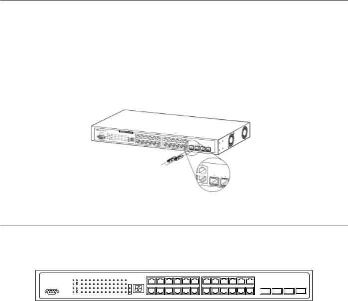
•SNMP support
•Secure Sockets Layer (SSL) and Secure Shell (SSH) support
•Port Mirroring support
•MIB support for:
RFC1213 MIB II
RFC1493 Bridge
RFC1757 RMON
RFC1643 Ether-like MIB
RFC2233 Interface MIB
IF MIB
Private MIB
RFC2674 for 802.1p
IEEE 802.1x MIB
•RS-232 DCE console port for Switch management
•Provides parallel LED display for port status such as link/act, speed, etc.
1-4 Ports
Twenty-four (24) 1000T combo ports that may be used in uplinking various network devices to the Switch, including PCs, hubs and other switches to provide a gigabit Ethernet uplink in full-duplex mode.
Four (4) high-performance SFP ports for a fibre-optic connection to various network connections, for use over great distances. Two 10-gigabit stacking ports at the rear of the Switch for stacking switches utilizing ring topology.
RS-232 DCE Diagnostic port (console port) for setting up and managing the Switch via a connection to a console terminal or PC using a terminal emulation program.
Installing the SFP ports
The Switch is equipped with four SFP (Small Form Factor Portable) ports, which are to be used with fibre-optical transceiver cabling in order to uplink various other networking devices for a gigabit link that may span great distances.
Figure 1- 1. Inserting the fibre-optic transceivers into the AT-9724TS
1-5 Front Panel Components
The front panel of the Switch consists of LED indicators for Power, Master, Console, RPS, SIO (stacking), a seven-segment Stack ID LED and for Link/Act for each port on the Switch, as well as 24 1000T ports, 4 SFP gigabit Ethernet ports and a RS-232 DCE console port for Switch management.
AT-9724TS
1 |
3 |
5 |
7 |
9 |
11 |
13 |
15 |
17 |
19 |
21 |
23 |
Power |
|
|
|
|
|
|
|
|
|
|
|
|
|
|
|
|
|
|
|
|
|
|
|
|
|
|
|
|
|
1000 |
|
|
|
|
|
|
|
|
|
|
|
|
Stack ID |
|
|
|
|
|
|
|
|
|
|
|
|
|
|
Master |
Link 1 |
3 |
5 |
7 |
9 |
11 |
13 |
15 |
17 |
19 |
21 |
23 |
SIO |
|
|
|
|
|
|
|
|
|
|
|
|
|
|
|
Console Act |
|
|
|
|
|
|
|
|
|
|
|
1 |
|
|
|
|
|
|
|
|
|
|
|
21 |
22 |
23 |
24 |
|
|
1000 |
|
|
|
|
|
|
|
|
|
|
|
|
|
|
|
|
|
|
|
|
|
|
|
||||
|
|
|
|
|
|
|
|
|
|
|
|
|
|
|
|
|
|
|
|
|
|
|
|
|
|
|
|
|
RPS |
Link 2 |
4 |
6 |
8 |
10 |
12 |
14 |
16 |
18 |
20 |
22 |
24 |
2 |
|
|
|
|
|
|
|
|
|
|
|
|
|
|
|
|
Act |
|
|
|
|
|
|
|
|
|
|
|
|
|
|
|
|
|
|
|
|
|
|
|
|
|
|
|
|
|
|
|
|
|
|
|
|
|
|
|
|
|
2 |
4 |
6 |
8 |
10 |
12 |
14 |
16 |
18 |
20 |
22 |
24 |
|
|
|
Figure 1- 2. Front Panel View of the AT-9724TS as shipped Comprehensive LED indicators display the status of the Switch and the network.
Allied Telesyn AT-9724TS High-Density Layer 3 Stackable Gigabit Ethernet Switch |
12 |

LED Indicators
The Switch supports LED indicators for Power, Master, Console, RPS, SIO (stacking indicators), a seven-segment Stack ID LED and Port LEDs.The following shows the LED indicators for the Switch along with an explanation of each indicator.
|
Figure 1- 3. LED Indicators |
LED Description |
|
Power |
This LED will light green after the Switch is powered on to indicate the ready state of the device.The indicator is dark when the Switch is |
|
powered off. |
Master |
This LED will light solid green when the Switch is configured to be a master switch of a switch stack in a ring topology or when it is in use as a |
|
stand-alone switch.This LED will remain dark if the Switch is not configured to be a master switch in a switch stack. |
Console |
This LED should blink during the Power-On Self Test (POST).When the POST is finished successfully, the LED goes dark.This indicator will light |
|
solid green when the Switch is being logged into via out-of-band/local console management through the RS-232 console port in the front of the |
|
Switch using a straight-through serial cable. |
|
This LED will light solid amber if the Power-On-Self-Test has failed. |
RPS |
This LED will be lit when the internal power has failed and the RPS has taken over the power supply to the Switch. Otherwise, it will remain |
|
dark. |
Port LEDs |
One row of LEDs for each port is located above the ports on the front panel.The first LED is for the top port and the second one is for the |
|
bottom ports.A solid light denotes activity on the port while a blinking light indicates a valid link.These LEDs will remain dark if there is no |
|
link/activity on the port. |
Stacking Ports |
|
(SIO) |
There are two LEDs in the front of the Switch marked SIO, and they relate to the two 10-gigabit stacking ports at the rear of the Switch.These |
|
LEDs are marked 1 and 2 and will light solid green to denote activity on the port, while a blinking light will indicate a valid link. |
Stack ID |
These two seven-segment LEDs display the current switch stack order of the Switch while in use. Possible numbers to be displayed range from |
|
1-12 in use. |
1-6 Rear Panel Components
The rear panel of the Switch contains an AC power connector, two 10-gigabit stacking ports and a redundant power supply connector.
Figure 1- 4. Rear panel view of the Switch
The AC power connector is a standard three-pronged connector that supports the power cord. Plug-in the female connector of the provided power cord into this socket, and the male side of the cord into a power outlet.The Switch automatically adjusts its power setting to any supply voltage in the range from 100 ~ 240 VAC at 50 ~ 60 Hz.
The rear panel also includes an outlet for an optional external power supply.When power fails, the optional external RPS will take over all the power immediately and automatically.
1-7 Side-Panel Components
The right-hand side panel of the Switch contains 2 system fans, while the left hand panel includes a heat vent.
The system fans are used to dissipate heat.The sides of the system also provide heat vents to serve the same purpose. Do not block these openings, and leave at least 6 inches of space at the rear and sides of the Switch for proper ventilation. Be reminded that without proper heat dissipation and air circulation, system components might overheat, which could lead to system failure.
Figure 1- 5. Side Panels
Allied Telesyn AT-9724TS High-Density Layer 3 Stackable Gigabit Ethernet Switch |
13 |

Chapter 2 - Installation
2-1 Package Contents
2-2 Before You Connect to the Network
2-3 Installing the Switch Without the Rack
2-4 Rack Installation
2-5 Power On
2-6 Power Failure
2-7 Redundant Power System
2-1 Package Contents
Open the shipping carton of the Switch and carefully unpack its contents.The carton should contain the following items:
•One AT-9724TS Switch
•One AC power cord
•One Stacking Cable
•One CD which includes the AT-9724TS Manual, and Net.Cover documents
•One Warranty Card
•Mounting kit (two brackets and screws)
•Four rubber feet with adhesive backing
•RS-232 console cable
•If any item is found missing or damaged, please contact your local Allied Telesyn Reseller for replacement.
2-2 Before You Connect to the Network
The site where you install the Switch may greatly affect its performance. Please follow these guidelines for setting up the Switch.
• Install the Switch on a sturdy, level surface that can support at least 6.6lb. (3kg) of weight. Do not place heavy objects on the Switch.
•The power outlet should be within 1.82 metres (6 feet) of the Switch.
• |
Visually inspect the power cord and see that it is fully secured to the AC power port. |
•Make sure that there is proper heat dissipation from and adequate ventilation around the Switch. Leave at least 10 cm (4 inches) of space at the front and rear of the Switch for ventilation.
•Install the Switch in a fairly cool and dry place for the acceptable temperature and humidity operating ranges.
•Install the Switch in a site free from strong electromagnetic field generators (such as motors), vibration, dust, and direct exposure to sunlight.
•When installing the Switch on a level surface, attach the rubber feet to the bottom of the device.The rubber feet cushion the Switch, protect the casing from scratches and prevent it from scratching other surfaces.
•Ensure you program the Switch with a valid IP address – see section xxxx.
2-3 Installing the Switch without a Rack
When installing the Switch on a desktop or shelf, the rubber feet included with the Switch should first be attached. Attach these cushioning feet on the bottom at each corner of the device. Allow enough ventilation space between the Switch and any other objects in the vicinity.
Allied Telesyn AT-9724TS High-Density Layer 3 Stackable Gigabit Ethernet Switch |
14 |

Figure 2- 1. Prepare Switch for installation on a desktop or shelf
2-4 Installing the Switch in a Rack
The Switch can be mounted in a standard 19" rack. Use the following diagrams to guide you.
Fasten the mounting brackets to the Switch using the screws provided.With the brackets attached securely, you can mount the Switch in a standard rack as shown in Figure 2-2.
Allied Telesyn AT-9724TS High-Density Layer 3 Stackable Gigabit Ethernet Switch |
15 |
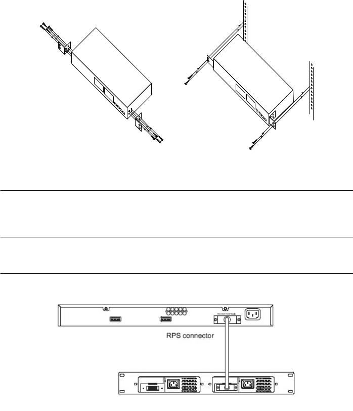
2-5 Mounting the Switch in a Standard 19" Rack
Figure 2- 2. Installing Switch in a rack
2-5 Power On
Plug one end of the AC power cord into the power connector of the Switch and the other end into the local power source outlet.
After the Switch is powered on, the LED indicators will momentarily blink.This blinking of the LED indicators represents a reset of the system.
2-6 Power Failure
As a precaution, in the event of a power failure, unplug the Switch.When power is resumed, plug the Switch back in.
2-7 External Redundant Power System
The Switch supports an external redundant power system.
Figure 2- 3.The AT-9724TS with the AT-RPS7000 Redundant External Power Supply
Allied Telesyn AT-9724TS High-Density Layer 3 Stackable Gigabit Ethernet Switch |
16 |

Chapter 3 - Connecting the Switch
•3-1 Switch to End Node
•3-2 Switch to Hub or Switch
•3-3 Connecting to Network Backbone or Server
•3-4 Stacking and the AT-9724TS
3-1 Switch To End Node
End nodes include PCs outfitted with a 10, 100 or 1000Mbps RJ45 Ethernet Network Interface Card (NIC) and most routers.
An end node can be connected to the Switch via a twisted-pair UTP/STP cable.The end node should be connected to any of the 24 1000T ports of the Switch.
Figure 3- 1. Switch connected to an end node
The Link/Act LEDs for each UTP port will light green or amber when the link is valid.A blinking LED indicates packet activity on that port.
3-2 Switch to Hub or Switch
These connections can be accomplished in a number of ways using a normal cable.
• A 10T hub or switch can be connected to the Switch via a twisted-pair Category 3, 4 or 5 UTP/STP cable.
•A 100TX hub or switch can be connected to the Switch via a twisted-pair Category 5 UTP/STP cable.
•A 1000T switch can be connected to the Switch via a twisted pair Category 5e UTP/STP cable.
•A switch supporting a fibre-optic uplink can be connected to the Switch’s SFP ports via fibre-optic cabling.
|
|
|
|
|
|
|
|
|
|
|
|
|
|
|
1 |
3 |
5 |
7 |
9 |
11 |
13 |
15 |
17 |
19 |
21 |
23 |
|
|
|
AT-9724TS |
Power |
Link 1 |
3 |
5 |
7 |
9 |
11 |
13 |
15 |
17 |
19 |
21 |
23 |
SIO |
Stack ID |
|
|
|
|
|
|
|
|
|
|
|
|
|
|
Master |
|
|
|
|
|
|
|
|
|
|
|
|
|
|
|||||||||||||||
|
|
1000 |
|
|
|
|
|
|
|
|
|
|
|
|
|
|
|
|
|
|
|
|
|
|
|
|
|
|
|
|
Console Act |
|
|
|
|
|
|
|
|
|
|
|
1 |
|
|
|
|
|
|
|
|
|
|
|
21 |
22 |
23 |
24 |
|
|
|
1000 |
|
|
|
|
|
|
|
|
|
|
|
|
|
|
|
|
|
|
|
|
|
|
|
||||
|
RPS |
Link 2 |
4 |
6 |
8 |
10 |
12 |
14 |
16 |
18 |
20 |
22 |
24 |
2 |
|
|
|
|
|
|
|
|
|
|
|
|
|
|
|
|
|
Act |
|
|
|
|
|
|
|
|
|
|
|
|
|
|
|
|
|
|
|
|
|
|
|
|
|
|
|
|
|
|
|
|
|
|
|
|
|
|
|
|
|
|
2 |
4 |
6 |
8 |
10 |
12 |
14 |
16 |
18 |
20 |
22 |
24 |
|
|
|
UTP cable
|
|
|
|
|
|
|
|
|
|
|
|
|
|
|
1 |
3 |
5 |
7 |
9 |
11 |
13 |
15 |
17 |
19 |
21 |
23 |
|
|
|
AT-9724TS |
Power |
Link 1 |
3 |
5 |
7 |
9 |
11 |
13 |
15 |
17 |
19 |
21 |
23 |
SIO |
Stack ID |
|
|
|
|
|
|
|
|
|
|
|
|
|
|
Master |
|
|
|
|
|
|
|
|
|
|
|
|
|
|
|||||||||||||||
|
|
1000 |
|
|
|
|
|
|
|
|
|
|
|
|
|
|
|
|
|
|
|
|
|
|
|
|
|
|
|
|
Console Act |
|
|
|
|
|
|
|
|
|
|
|
1 |
|
|
|
|
|
|
|
|
|
|
|
21 |
22 |
23 |
24 |
|
|
|
1000 |
|
|
|
|
|
|
|
|
|
|
|
|
|
|
|
|
|
|
|
|
|
|
|
||||
|
RPS |
Link 2 |
4 |
6 |
8 |
10 |
12 |
14 |
16 |
18 |
20 |
22 |
24 |
2 |
|
|
|
|
|
|
|
|
|
|
|
|
|
|
|
|
|
Act |
|
|
|
|
|
|
|
|
|
|
|
|
|
|
|
|
|
|
|
|
|
|
|
|
|
|
|
|
|
|
|
|
|
|
|
|
|
|
|
|
|
|
2 |
4 |
6 |
8 |
10 |
12 |
14 |
16 |
18 |
20 |
22 |
24 |
|
|
|
Figure 3- 2. Switch connected to a port on a hub or switch using either a straight or crossover cable – any normal cable is fine
Allied Telesyn AT-9724TS High-Density Layer 3 Stackable Gigabit Ethernet Switch |
17 |

AT-9724TS |
Power |
1 |
Master Link |
||
|
1000 |
|
Console Act

 1000
1000
RPS Link 2

 Act
Act
1 |
3 |
5 |
7 |
9 |
11 |
13 |
15 |
17 |
19 |
21 |
23 |
3 |
5 |
7 |
9 |
11 |
13 |
15 |
17 |
19 |
21 |
23 |
SIO |
Stack ID |
|
|
|
|
|
|
|
|
|
|
|
|
|
|
|
|
|
|
|
|
|
|
|
|
|
1 |
|
|
|
|
|
|
|
|
|
|
|
21 |
22 |
23 |
24 |
4 |
6 |
8 |
10 |
12 |
14 |
16 |
18 |
20 |
22 |
24 |
2 |
|
|
|
|
|
|
|
|
|
|
|
|
|
|
|
|
|
|
|
|
|
|
|
|
|
|
|
2 |
4 |
6 |
8 |
10 |
12 |
14 |
16 |
18 |
20 |
22 |
24 |
|
|
|
Optical fibre cable
AT-9724TS |
Power |
1 |
Master Link |
||
|
1000 |
|
Console Act

 1000
1000
RPS Link 2

 Act
Act
1 |
3 |
5 |
7 |
9 |
11 |
13 |
15 |
17 |
19 |
21 |
23 |
3 |
5 |
7 |
9 |
11 |
13 |
15 |
17 |
19 |
21 |
23 |
SIO |
Stack ID |
|
|
|
|
|
|
|
|
|
|
|
|
|
|
|
|
|
|
|
|
|
|
|
|
|
1 |
|
|
|
|
|
|
|
|
|
|
|
21 |
22 |
23 |
24 |
4 |
6 |
8 |
10 |
12 |
14 |
16 |
18 |
20 |
22 |
24 |
2 |
|
|
|
|
|
|
|
|
|
|
|
|
|
|
|
|
|
|
|
|
|
|
|
|
|
|
|
2 |
4 |
6 |
8 |
10 |
12 |
14 |
16 |
18 |
20 |
22 |
24 |
|
|
|
Figure 3- 3. Switch connected to switch using fibre-optic cabling
3-3 Connecting To Network Backbone or Server
The 4 combo SFP ports and the 24 1000T ports are ideal for uplinking to a network backbone, server or server farm.The copper ports operate at a speed of 1000, 100 or 10Mbps in full or half duplex mode.The fibre-optic ports can operate at 1000Mbps in full duplex mode only.
Connections to the Gigabit Ethernet ports are made using fibre-optic cable or Category 5e copper cable, depending on the type of port. A valid connection is indicated when the Link LED is lit.
3-4 Stacking and the AT-9724TS
The AT-9724TS is equipped with two 10-gigabit stacking ports at the rear of the Switch, as seen in Figure 3-5.These stacking ports may be used to stack the AT9724TS to a master switch to be used in a switch stack.
Figure 3- 5. SIO 1 and SIO 2 Stacking ports at the rear of the AT-9724TS
These two stacking ports, named SIO 1 and SIO 2 can be used with other stacking switches for a scalable stacking solution of up to 288 ports in a ring topology. These two stacking ports have corresponding LEDs at the front of the Switch, labelled SIO 1 and SIO 2 will light solid green whenever the corresponding port is in use.
Figure 3- 6. Stacking LEDs (SIO) at the front of the AT-9724TS
Allied Telesyn AT-9724TS High-Density Layer 3 Stackable Gigabit Ethernet Switch |
18 |
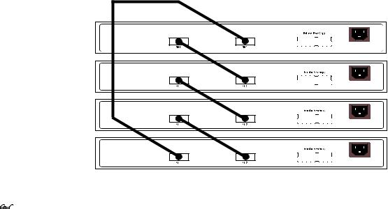
Figure 3- 8. Stacking in a Ring Architecture
Note: The Do not connect the stacked Switch group to the network until you have properly configured all Switches for stacking. An improperly configured Switch stack can cause a broadcast storm.
Stacking Limitations Utilizing a Ring Topology
There is a limit to the number of AT-9724TS Switches that can be stacked in a ring topology. A maximum of 12 switches can be stacked. 
 Note: All Switches must have the same firmware rev.
Allied Telesyn AT-9724TS High-Density Layer 3 Stackable Gigabit Ethernet Switch |
19 |
Chapter 4 - Introduction to Switch Management
4-1 AT-9724TS Gigabit Layer 3 Switch Management Options 4-2 Web-based Management Interface
4-3 SNMP-Based Management
4-4 Command Line Console Interface Through The Serial Port 4-5 Connecting the Console Port (RS-232 DCE)
4-6 First Time Connecting to The Switch
4-7 Password Protection
4-8 SNMP Settings
4-9 IP Address Assignment
4-10 Connecting Devices to the Switch
4-1 AT-9724TS Gigabit Layer 3 Switch Management Options
This system may be managed out-of-band through the console port on the front panel or in-band using Telnet.The user may also choose the web-based management, accessible through a web browser.
4-2 Web-based Management Interface
After you have successfully installed the Switch, you can configure the Switch, monitor the LED panel, and display statistics graphically using a web browser, such as Netscape Navigator (version 6.2 and higher) or Microsoft® Internet Explorer (version 5.0).
4-3 SNMP-Based Management
You can manage the Switch with an SNMP-compatible console program.The Switch supports SNMP version 1.0, version 2.0 and version 3.0.The SNMP agent decodes the incoming SNMP messages and responds to requests with MIB objects stored in the database.The SNMP agent updates the MIB objects to generate statistics and counters.
4-4 Command Line Console Interface Through The Serial Port
You can also connect a computer or terminal to the serial console port to access the Switch.The command-line-driven interface provides complete access to all Switch management features.
4-5 Connecting the Console Port (RS-232 DCE)
The Switch provides an RS-232 serial port that enables a connection to a computer or terminal for monitoring and configuring the Switch.This port is a female DB-9 connector, implemented as a data terminal equipment (DTE) connection.
To use the console port, you need the following equipment:
•A terminal or a computer with both a serial port and the ability to emulate a terminal.
•A null modem or crossover RS-232 cable with a female DB-9 connector for the console port on the Switch (supplied with the switch).
To connect a terminal to the console port:
1. Connect the female connector of the RS-232 cable directly to the console port on the Switch, and tighten the captive retaining screws.
2.Connect the other end of the cable to a terminal or to the serial connector of a computer running terminal emulation software. Set the terminal emulation software as follows:
3.Select the appropriate serial port (COM port 1 or COM port 2).
4.Set the data rate to 115200 baud.
5.Set the data format to 8 data bits, 1 stop bit, and no parity.
6.Set flow control to none.
7.Under Properties, select VT100 for Emulation mode.
8.Select Terminal keys for Function,Arrow, and Ctrl keys. Ensure that you select Terminal keys (not Windows keys).
Note: When you use HyperTerminal with the Microsoft® Windows® 2000 operating system, ensure that you have Windows 2000 Service Pack 2 or later installed.Windows 2000 Service Pack 2 allows you to use arrow keys in HyperTerminal's VT100 emulation. See www.microsoft.com for information on Windows 2000 service packs.
Allied Telesyn AT-9724TS High-Density Layer 3 Stackable Gigabit Ethernet Switch |
20 |
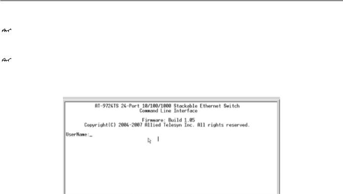
9.After you have correctly set up the terminal, plug the power cable into the power receptacle on the back of the Switch.The boot sequence appears in the terminal.
10.After the boot sequence completes, the console login screen displays.
11.If you have not logged into the command line interface (CLI) program, press the Enter key at the User name and password prompts.There is one default user name and password for the Switch. User names and passwords must first be created by the administrator. If you have previously set up user accounts, log in and continue to configure the Switch.
12.Enter the commands to complete your desired tasks. Many commands require administrator-level access privileges. Read the next section for more information on setting up user accounts. See the AT-9724TS Command Line Interface Reference Manual on the documentation CD for a list of all commands and additional information on using the CLI.
13.When you have completed your tasks, exit the session with the logout command or close the emulator program.
Make sure the terminal or PC you are using to make this connection is configured to match these settings.
If you are having problems making this connection on a PC, make sure the emulation is set to VT-100.You will be able to set the emulation by clicking on the File menu in you HyperTerminal window, clicking on Properties in the drop-down menu, and then clicking the Settings tab.This is where you will find the Emulation options. If you still do not see anything, try rebooting the Switch by disconnecting its power supply.
Once connected to the console, the screen below will appear on your console screen.This is where the user will enter commands to perform all the available management functions.The Switch will prompt the user to enter a user name and a password. Upon the initial connection, there is no user name or password and therefore just press enter twice to access the command line interface.
4-6 First Time Connecting to the Switch
The Switch supports user-based security that can allow you to prevent unauthorized users from accessing the Switch or changing its settings.This section tells how to log onto the Switch.
Note: The passwords used to access the Switch are case-sensitive; therefore, "S" is not the same as "s." When you first connect to the Switch, you will be presented with the first login screen (shown below).
Note: Press Ctrl+R to refresh the screen.This command can be used at any time to force the console program in the Switch to refresh the console screen.
Figure 4- 1. Initial screen, first time connecting to the Switch
The initial username and password are:
Username: manager
Password: friend
You will be given access to the command prompt AT-9724TS:4# shown below.
Allied Telesyn AT-9724TS High-Density Layer 3 Stackable Gigabit Ethernet Switch |
21 |

Figure 4- 2. Command Prompt
Note: The first user automatically gets Administrator level privileges. It is recommended to create at least one Admin-level user account for the Switch.
4-7 Password Protection
One of the first tasks when settings up the Switch is to create user accounts. If you log in using a predefined administrator-level user name, you have privileged access to the Switch's management software.
After your initial login, define new passwords for both default user names to prevent unauthorized access to the Switch, and record the passwords for future reference.
To create an administrator-level account for the Switch, do the following:
At the CLI login prompt, enter create account admin followed by the <user name> and press the Enter key.
You will be asked to provide a password.Type the <password> used for the administrator account being created and press the Enter key. You will be prompted to enter the same password again to verify it.Type the same password and press the Enter key.
Successful creation of the new administrator account will be verified by a Success message.
Note: Passwords are case sensitive. User names and passwords can be up to 15 characters in length.
The sample below illustrates a successful creation of a new administrator-level account with the user name "newmanager".
AT-9724TS:4#create account admin newmanager
Command: create account admin newmanager
Enter a case-sensitive new password:********
Enter the new password again for confirmation:********
Success.
AT-9724TS:4#
mCaution: CLI configuration commands only modify the running configuration file and are not saved when the Switch is rebooted.To save all your configuration changes in nonvolatile storage, you must use the save command to copy the running configuration file to the startup configuration.
4-8 SNMP Settings
Simple Network Management Protocol (SNMP) is an OSI Layer 7 (Application Layer) designed specifically for managing and monitoring network devices. SNMP enables network management stations to read and modify the settings of gateways, routers, switches, and other network devices. Use SNMP to configure system features for proper operation, monitor performance and detect potential problems in the Switch, switch group or network.
Managed devices that support SNMP include software (referred to as an agent), which runs locally on the device.A defined set of variables (managed objects) is maintained by the SNMP agent and used to manage the device.These objects are defined in a Management Information Base (MIB), which provides a standard presentation of the information controlled by the on-board SNMP agent. SNMP defines both the format of the MIB specifications and the protocol used to access this information over the network.
Allied Telesyn AT-9724TS High-Density Layer 3 Stackable Gigabit Ethernet Switch |
22 |
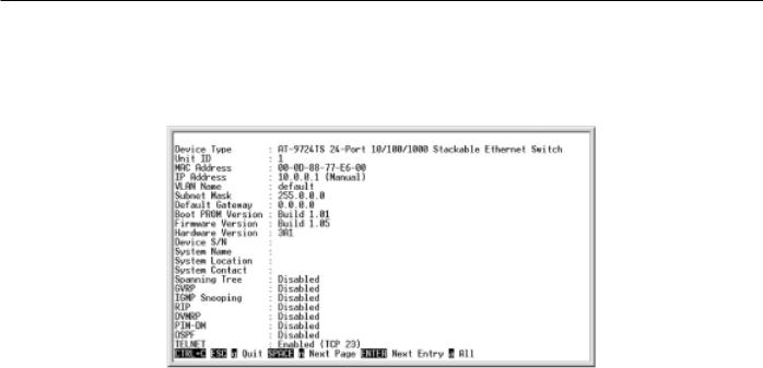
The AT-9724TS supports SNMP versions 1, 2c, and 3.You can specify which version of SNMP you want to use to monitor and control the Switch.The three versions of SNMP vary in the level of security provided between the management station and the network device.
In SNMP v.1 and v.2, user authentication is accomplished using 'community strings', which function like passwords.The remote user SNMP application and the Switch SNMP must use the same community string. SNMP packets from any station that has not been authenticated are ignored (dropped).
The default community strings for the Switch used for SNMP v.1 and v.2 management access are: public – Allows authorized management stations to retrieve MIB objects.
private – Allows authorized management stations to retrieve and modify MIB objects.
SNMP v.3 uses a more sophisticated authentication process that is separated into two parts.The first part is to maintain a list of users and their attributes that are allowed to act as SNMP managers.The second part describes what each user on that list can do as an SNMP manager.
The Switch allows groups of users to be listed and configured with a shared set of privileges.The SNMP version may also be set for a listed group of SNMP managers.Thus, you may create a group of SNMP managers that are allowed to view read-only information or receive traps using SNMP v.1 while assigning a higher level of security to another group, granting read/write privileges using SNMP v.3.
Using SNMP v.3 individual users or groups of SNMP managers can be allowed to perform or be restricted from performing specific SNMP management functions.The functions allowed or restricted are defined using the Object Identifier (OID) associated with a specific MIB.An additional layer of security is available for SNMP v.3 in that SNMP messages may be encrypted.To read more about how to configure SNMP v.3 settings for the Switch read the section entitled Management.
Traps
Traps are messages that alert network personnel of events that occur on the Switch.The events can be as serious as a reboot (someone accidentally turned OFF the Switch), or less serious like a port status change.The Switch generates traps and sends them to the trap recipient (or network manager).Typical traps include trap messages for Authentication Failure,Topology Change and Broadcast/Multicast Storm.
MIBs
Management and counter information are stored by the Switch in the Management Information Base (MIB).The Switch uses the standard MIB-II Management Information Base module. Consequently, values for MIB objects can be retrieved from any SNMP-based network management software. In addition to the standard MIB-II, the Switch also supports its own proprietary enterprise MIB as an extended Management Information Base.The proprietary MIB may also be retrieved by specifying the MIB Object Identifier. MIB values can be either read-only or read-write.
4-9 IP Address Assignment
Each Switch must be assigned its own IP Address, which is used for communication with an SNMP network manager or other TCP/IP application (for example BOOTP,TFTP).The Switch's default IP address is 10.0.0.1.You can change the default Switch IP address to meet the specification of your networking address scheme.
The Switch is also assigned a unique MAC address by the factory.This MAC address cannot be changed, and can be found by entering the command "show switch" into the command line interface, as shown below.
Figure 4- 3.“show switch” command
The Switch's MAC address can also be found from the Web management program on the Switch Information (Basic Settings) window in the
Configuration menu.
The IP address for the Switch must be set before it can be managed with the Web-based manager.The Switch IP address can be automatically set using BOOTP or DHCP protocols, in which case the actual address assigned to the Switch must be known.
The IP address may be set using the Command Line Interface (CLI) over the console serial port as follows:
Starting at the command line prompt, enter the commands config ipif System ipaddress xxx.xxx.xxx.xxx/yyy.yyy.yyy.yyy.Where the x's represent the IP address to be assigned to the IP interface named System and the y's represent the corresponding subnet mask.
Allied Telesyn AT-9724TS High-Density Layer 3 Stackable Gigabit Ethernet Switch |
23 |

Alternatively, you can enter config ipif System ipaddress xxx.xxx.xxx.xxx/z.Where the x's represent the IP address to be assigned to the IP interface named System and the z represents the corresponding number of subnets in CIDR notation.
The IP interface named System on the Switch can be assigned an IP address and subnet mask which can then be used to connect a management station to the Switch's Telnet or Web-based management agent.
Figure 4- 4.Assigning the Switch an IP Address
In the above example, the Switch was assigned an IP address of 10.53.13.144 with a subnet mask of 255.0.0.0.The system message Success indicates that the command was executed successfully.The Switch can now be configured and managed via Telnet and the CLI or via the Web-based management.
4-10 Connecting Devices to the Switch
After you assign IP addresses to the Switch, you can connect devices to the Switch.
To connect a device to an SFP transceiver port:
•Use your cabling requirements to select an appropriate SFP transceiver type.
•Insert the SFP transceiver (sold separately) into the SFP transceiver slot.
•Use the appropriate network cabling to connect a device to the connectors on the SFP transceiver.
m Caution: When the SFP transceiver acquires a link, the associated integrated 10/100/1000T port is disabled.
Allied Telesyn AT-9724TS High-Density Layer 3 Stackable Gigabit Ethernet Switch |
24 |
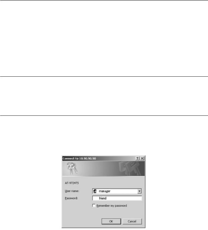
Chapter 5 - Introduction to Web-based Switch Configuration
5-1 Introduction
5-2 Login to Web manager
5-3 Web-Based User Interface
5-4 Basic Setup
5-5 Reboot
5-6 Basic Switch Setup
5-7 Network Management
5-8 Switch Utilities
5-9 Network Monitoring
5-10 IGMP Snooping Status
5-1 Introduction
All software functions of the AT-9724TS can be managed, configured and monitored via the embedded web-based (HTML) interface.The Switch can be managed from remote stations anywhere on the network through a standard browser such as Netscape Navigator/Communicator or Microsoft Internet Explorer.The browser acts as a universal access tool and can communicate directly with the Switch using the HTTP protocol.
The Web-based management module and the Console program (and Telnet) are different ways to access the same internal switching software and configure it. Thus, all settings encountered in web-based management are the same as those found in the console program.
5-2 Login to Web Manager
To begin managing your Switch, simply run the browser you have installed on your computer and point it to the IP address you have defined for the device.The URL in the address bar should read something like: http://123.123.123.123, where the numbers 123 represent the IP address of the Switch.

 Note: The Factory default IP address for the Switch is 10.0.0.1.
Figure 5- 1. Login Button
This opens the management module's user authentication window, as seen below.
Allied Telesyn AT-9724TS High-Density Layer 3 Stackable Gigabit Ethernet Switch |
25 |

5-3 Web-based User Interface
The user interface provides access to various Switch configuration and management screens, allows you to view performance statistics, and permits you to graphically monitor the system status.
Areas of the User Interface
The figure below shows the user interface.The user interface is divided into 3 distinct areas as described in the table.
Figure 5- 2. Main Web-Manager Screen
Area |
Function |
1Select the menu or window to be displayed.The folder icons can be opened to display the hyperlinked menu buttons and subfolders contained within them. Click the Allied Telesyn logo to go to the Allied Telesyn website.
2Presents a graphical near real-time image of the front panel of the Switch.This area displays the Switch's ports and expansion modules, showing port activity, duplex mode, or flow control, depending on the specified mode.Various areas of the graphic can be selected for performing management functions, including port configuration.
3Presents switch information based on your selection and the entry of configuration data.
mCaution: Any changes made to the Switch configuration during the current session must be saved in the Save Changes web menu (explained below) or use the command line interface (CLI) command save.
Allied Telesyn AT-9724TS High-Density Layer 3 Stackable Gigabit Ethernet Switch |
26 |

Web Pages
Configurations – Contains screens concerning configurations for IP Address, Switch Information,Advanced Settings, Port Configuration, IGMP, Spanning Tree, Forwarding Filtering,VLANs, Port Bandwidth, SNTP Settings, Port Security, QoS, MAC Notification, LACP,Access Profile Table, System Log Servers, PAE Access Entity, and Layer 3 IP Networking.
Security Management – Contains screens concerning configurations for Security IP, User Accounts,Access Authentication Control (TACACS), Secure Sockets Layer (SSL), and Secure Shell (SSH).
SNMP Manager – Contains screens and windows concerning the implementation and upkeep of the SNMP Manager of the Switch.
Monitoring – Contains screens concerning monitoring the Switch, pertaining to Port Utilization, CPU Utilization, Packets, Errors Size, MAC Address, IGMP Snooping Group, IGMP Snooping Forwarding,VLAN Status, Router Port, Port Access Control and Layer 3 Feature.
Maintenance – Contains screens concerning configurations and information about Switch maintenance, including TFTP Services, CF Services, Dual Image Information, Switch History, Ping Test, Save Changes, Reboot Services and Logout.
Single IP Management – Contains screens concerning information on Single IP Management, including SIM Settings,Topology and Firmware/Configuration downloads.
Note: Be sure to configure the user name and password in the User Accounts menu before connecting the Switch to the greater network.
Allied Telesyn AT-9724TS High-Density Layer 3 Stackable Gigabit Ethernet Switch |
27 |
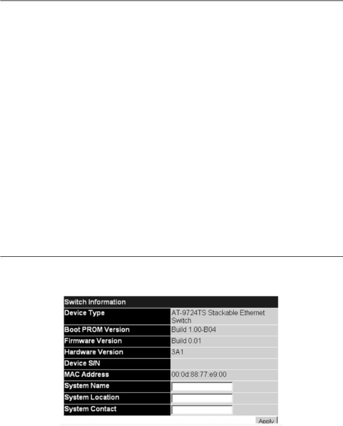
Chapter 6 - Configuring The Switch
6-1 Switch Information
6-2 IP Address
6-3 Box Information
6-4 Advanced Settings
6-5 Port Configuration
6-6 Port Description
6-7 Port Mirroring
6-8 Link Aggregation
6-9 LACP Port Setting
6-10MAC Notification
6-11GMP
6-12 Spanning Tree
6-13 Forward & Filtering
6-14 VLANs
6-15 Traffic Control
6-16 Port Security
6-17 Port Lock Entries
6-18 QoS
6-19 System Log Servers
6-20 SNTP Setting
6-21 Access Profile Table
6-22 Port Access Entity
6-23 Layer 3 IP Networking
6-1 Switch Information
The subsections below describe how to change some of the basic settings for the Switch such as changing IP settings and assigning user names and passwords for management access privileges, as well as how to save the changes and restart the Switch.
Click the Switch Information link in the Configuration menu.
Figure 6- 1. Switch Information – Basic Settings window
The Switch Information window shows the Switch's MAC Address (assigned by the factory and unchangeable), the Boot PROM, Firmware Version, and Hardware Version.This information is helpful to keep track of PROM and firmware updates and to obtain the Switch's MAC address for entry into another network device's address table, if necessary.The user may also enter a System Name, System Location and System Contact to aid in defining the Switch, to the user's preference.
Allied Telesyn AT-9724TS High-Density Layer 3 Stackable Gigabit Ethernet Switch |
28 |
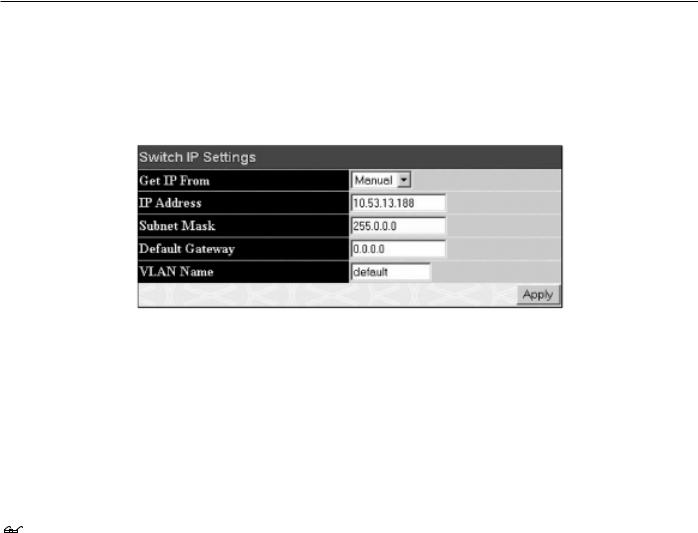
6-2 IP Address
The IP Address may initially be set using the console interface prior to connecting to it through the Ethernet. If the Switch IP address has not yet been changed, read the introduction of the AT-9724TS Command Line Interface Reference Manual or return to Chapter 4 of this manual for more information.
To change IP settings using the web manager you must access the IP Address menu located in the Configuration folder.
To configure the Switch's IP address:
Open the Configuration folder and click the IP Address menu link.The web manager will display the Switch's current IP settings in the IP configuration menu, as seen below.
Figure 6- 2. IP Address Settings window
To manually assign the Switch's IP address, subnet mask, and default gateway address:
1.Select Manual from the Get IP From drop-down menu.
2.Enter the appropriate IP Address and Subnet Mask.
3.If you want to access the Switch from a different subnet from the one it is installed on, enter the IP address of the Default Gateway. If you will manage the Switch from the subnet on which it is installed, you can leave the default address (0.0.0.0) in this field.
4. |
If no VLANs have been previously configured on the Switch, you can use the default VLAN Name.The default VLAN contains all of the Switch ports |
|
as members. If VLANs have been previously configured on the Switch, you will need to enter the VLAN ID of the VLAN that contains the port |
|
connected to the management station that will access the Switch.The Switch will allow management access from stations with the same VID listed |
|
here. |
Note: The Switch's factory default IP address is 10.0.0.1 with a subnet mask of 255.0.0.0 and a default gateway of 0.0.0.0.
To use the BOOTP or DHCP protocols to assign the Switch an IP address, subnet mask, and default gateway address:
Use the Get IP From: <Manual> pull-down menu to choose from BOOTP or DHCP.This selects how the Switch will be assigned an IP address on the next reboot.
The IP Address Settings options are:
Parameter |
Description |
|
|
|
|
BOOTP |
The Switch will send out a BOOTP broadcast request when it is powered up.The BOOTP protocol allows IP |
|
|
addresses, network masks, and default gateways to be assigned by a central BOOTP server. If this option is set, |
|
|
the Switch will first look for a BOOTP server to provide it with this information before using the default or |
|
|
previously entered settings. |
|
DHCP |
The Switch will send out a DHCP broadcast request when it is powered up.The DHCP protocol allows IP |
|
|
addresses, network masks, and default gateways to be assigned by a DHCP server. If this option is set, the |
|
|
Switch will first look for a DHCP server to provide it with this information before using the default or |
|
|
previously entered settings. |
|
Manual |
Allows the entry of an IP address, Subnet Mask, and a Default Gateway for the Switch.These fields should be of |
|
|
the form xxx.xxx.xxx.xxx, where each xxx is a number (represented in decimal form) between 0 and 255.This |
|
|
address should be a unique address on the network assigned for use by the network administrator. |
|
Subnet Mask A |
Bitmask that determines the extent of the subnet that the Switch is on. Should be of the form |
|
|
xxx.xxx.xxx.xxx, where each xxx is a number (represented in decimal) between 0 and 255.The value |
|
|
should be 255.0.0.0 for a Class A network, 255.255.0.0 for a Class B network, and 255.255.255.0 for a Class C |
|
|
network, but custom subnet masks are allowed. |
|
Default Gateway |
IP address that determines where packets with a destination address outside the current subnet should be |
|
|
sent.This is usually the address of a router or a host acting as an IP gateway. If your network is not part of an |
|
|
intranet, or you do not want the Switch to be accessible outside your local network, you can leave this field |
|
|
unchanged. |
|
Allied Telesyn AT-9724TS High-Density Layer 3 Stackable Gigabit Ethernet Switch |
29 |
 Loading...