


Alliance Laundry Systems UC35, UC80, HC50, UC50, SC18 User Manual
...Washer-Extractor
Cabinet Hardmount
2-Speed, 3-Speed, and Variable-Speed
|
Model Numbers |
|
HC18 |
SC18 |
UC18 |
HC25 |
SC25 |
UC25 |
HC27 |
SîC27 |
UC27 |
HC35 |
SC35 |
UC35 |
HC50 |
SC50 |
UC50 |
HC80 |
SC80 |
UC80 |
(See inside for complete model number list.)
NOTA: El manual en español aparece después del manual en inglés.
Installation/Maintenance
Part No. F232062R4
May 1999

Model Number Chart
HC18EC2 |
HC35MD2 |
SC18MC3 |
SC27SN2 |
SC50MN3 |
UC18PN3 |
UC35VNV |
|
|
|
|
|
|
|
HC18MC2 |
HC35MH2 |
SC18MD2 |
SC27VN2 |
SC50MV2 |
UC18VN2 |
UC50MC2 |
|
|
|
|
|
|
|
HC18MD2 |
HC35MN2 |
SC18MD3 |
SC27VNV |
SC50MV3 |
UC18VNV |
UC50MC3 |
|
|
|
|
|
|
|
HC18MH2 |
HC35MV2 |
SC18MH2 |
SC35EC2 |
SC50SN2 |
UC25MC2 |
UC50MD2 |
|
|
|
|
|
|
|
HC18MN2 |
HC35PC2 |
SC18MH3 |
SC35EP2 |
SC50VN2 |
UC25MD2 |
UC50MD3 |
|
|
|
|
|
|
|
HC18MV2 |
HC35SN2 |
SC18MN2 |
SC35MC2 |
SC50VNV |
UC25MH2 |
UC50MH2 |
|
|
|
|
|
|
|
HC18PC2 |
HC35VC2 |
SC18MN3 |
SC35MC3 |
SC80ECV |
UC25MN2 |
UC50MH3 |
|
|
|
|
|
|
|
HC18SN2 |
HC50EC2 |
SC18MV2 |
SC35MD2 |
SC80EPV |
UC25MV2 |
UC50MN2 |
|
|
|
|
|
|
|
HC18VC2 |
HC50MC2 |
SC18MV3 |
SC35MD3 |
SC80MC3 |
UC25PC2 |
UC50MN3 |
|
|
|
|
|
|
|
HC25EC2 |
HC50MD2 |
SC18SN2 |
SC35MH2 |
SC80MD3 |
UC25PN2 |
UC50MV2 |
|
|
|
|
|
|
|
HC25MC2 |
HC50MH2 |
SC18SN3 |
SC35MH3 |
SC80MH3 |
UC27MN2 |
UC50MV3 |
|
|
|
|
|
|
|
HC25MD2 |
HC50MN2 |
SC18VN2 |
SC35MN2 |
SC80MN3 |
UC27PN2 |
UC50PC2 |
|
|
|
|
|
|
|
HC25MH2 |
HC50MV2 |
SC18VNV |
SC35MN3 |
SC80MV3 |
UC27VN2 |
UC50PC3 |
|
|
|
|
|
|
|
HC25MN2 |
HC50PC2 |
SC25EC2 |
SC35MV2 |
SC80SN3 |
UC35MC2 |
UC50PN2 |
|
|
|
|
|
|
|
HC25MV2 |
HC50SN2 |
SC25EP2 |
SC35MV3 |
SC80VNV |
UC35MC3 |
UC50PN3 |
|
|
|
|
|
|
|
HC25PC2 |
HC50VC2 |
SC25MC2 |
SC35SN2 |
UC18MC2 |
UC35MD2 |
UC50VN2 |
|
|
|
|
|
|
|
HC25SN2 |
HC80MC3 |
SC25MD2 |
SC35SN3 |
UC18MC3 |
UC35MD3 |
UC50VNV |
|
|
|
|
|
|
|
HC25VC2 |
HC80MD3 |
SC25MH2 |
SC35VN2 |
UC18MD2 |
UC35MH2 |
UC80MC3 |
|
|
|
|
|
|
|
HC27EC2 |
HC80MH3 |
SC25MN2 |
SC35VNV |
UC18MD3 |
UC35MH3 |
UC80MD3 |
|
|
|
|
|
|
|
HC27MC2 |
HC80MN3 |
SC25MV2 |
SC50EC2 |
UC18MH2 |
UC35MN2 |
UC80MH3 |
|
|
|
|
|
|
|
HC27MD2 |
HC80MV3 |
SC25SN2 |
SC50EP2 |
UC18MH3 |
UC35MN3 |
UC80MN3 |
|
|
|
|
|
|
|
HC27MH2 |
HC80PC3 |
SC27EC2 |
SC50MC2 |
UC18MN2 |
UC35MV2 |
UC80MV3 |
|
|
|
|
|
|
|
HC27MN2 |
HC80SN3 |
SC27EP2 |
SC50MC3 |
UC18MN3 |
UC35MV3 |
UC80PC3 |
|
|
|
|
|
|
|
HC27MV2 |
HC80VCV |
SC27MC2 |
SC50MD2 |
UC18MV2 |
UC35PC2 |
UC80PN3 |
|
|
|
|
|
|
|
HC27SN2 |
HC80VNV |
SC27MD2 |
SC50MD3 |
UC18MV3 |
UC35PC3 |
UC80VNV |
|
|
|
|
|
|
|
HC27VC2 |
SC18EC2 |
SC27MH2 |
SC50MH2 |
UC18PC2 |
UC35PN2 |
|
|
|
|
|
|
|
|
HC35EC2 |
SC18EP2 |
SC27MN2 |
SC50MH3 |
UC18PC3 |
UC35PN3 |
|
|
|
|
|
|
|
|
HC35MC2 |
SC18MC2 |
SC27MV2 |
SC50MN2 |
UC18PN2 |
UC35VN2 |
|
|
|
|
|
|
|
|

Table of Contents
Installation/Maintenance
Safety |
|
Key to Symbols ................................................ |
4 |
Safety Decal Location ...................................... |
5 |
Operator Safety ................................................ |
6 |
Safe Operating Environment ............................ |
7 |
Environmental Conditions ............................ |
7 |
Machine Location ......................................... |
8 |
Input and Output Services ............................ |
8 |
AC Inverter Drive ......................................... |
9 |
Misuse .............................................................. |
9 |
Installation |
|
Machine Overview ........................................... |
11 |
Delivery Inspection .......................................... |
12 |
Customer Service ............................................. |
12 |
Model Number Familiarization Guide ............. |
13 |
General Specifications ..................................... |
14 |
Machine Dimensions ........................................ |
20 |
Dimensional Clearances ................................... |
27 |
Machine Foundation ........................................ |
29 |
Mechanical Installation .................................... |
31 |
Expansion Bolt Installation .......................... |
31 |
Elevated Base Frame Installation ................. |
33 |
J-Bolt Installation ......................................... |
35 |
Concrete Foundation Pad ............................. |
39 |
Drain Connection ............................................. |
42 |
Water Connection ............................................ |
44 |
Electrical Installation ....................................... |
45 |
Steam Requirements (Steam Heat |
|
Option Only) .................................................... |
52 |
Chemical Injection Supply System .................. |
53 |
Control Function Test ...................................... |
57 |
Maintenance |
|
Daily ................................................................ |
59 |
Beginning Of Day ........................................ |
59 |
End Of Day .................................................. |
60 |
Weekly ............................................................. |
60 |
Monthly ........................................................... |
60 |
Quarterly .......................................................... |
64 |
Care Of Stainless Steel .................................... |
65 |
Maintenance Checklists ................................... |
66 |
Removal from Service |
|
Decommissioning ............................................ |
71 |
1
F232062
© Copyright 1999 Alliance Laundry Systems LLC
All rights reserved. No part of the contents of this book may be reproduced or transmitted in any form or by any means without the expressed written consent of the publisher.
F232062
Section 1
Safety
Anyone operating or servicing this machine must follow the safety rules in this manual. Particular attention must be paid to the
DANGER, WARNING, and CAUTION blocks which appear throughout the manual.
The following warnings are general examples that apply to this machine. Warnings specific to a particular installation or maintenance procedure will appear in the manual with the discussion of that procedure.
CAUTION
Be careful around the open door, particularly when loading from a level below the door. Impact with door edges can cause personal injury.
SW025
DANGER
Death or serious injury can result if children become trapped in the machine. Do not allow children to play on or around this machine. Do not leave children unattended while the machine door is open.
SW001
WARNING
Dangerous voltages are present in the electrical control box(es) and at the motor terminals. Only qualified personnel familiar with electrical test procedures, test equipment, and safety precautions should attempt adjustments and troubleshooting. Disconnect power from the machine before removing the control box cover, and before attempting any service procedures.
SW005
WARNING
This machine must be installed, adjusted, and serviced by qualified electrical maintenance personnel familiar with the construction and operation of this type of machinery. They must also be familiar with the potential hazards involved. Failure to observe this warning may result in personal injury and/or equipment damage, and may void the warranty.
SW004
3
F232062
Safety
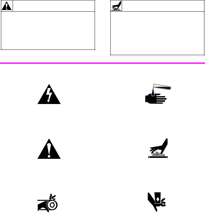
CAUTION
Ensure that the machine is installed on a level floor of sufficient strength and that the recommended clearances for inspection and maintenance are provided. Never allow the inspection and maintenance space to be blocked.
SW020
WARNING
Never touch internal or external steam pipes, connections, or components. These surfaces can be extremely hot and will cause severe burns. The steam must be turned off and the pipe, connections, and components allowed to cool before the pipe can be touched.
SW014
Key To Symbols
The lightning flash and arrowhead within the triangle is a warning sign indicating the presence of dangerous voltage.
The exclamation point within the triangle is a warning sign indicating important instructions concerning the machine and possibly dangerous conditions.
This warning symbol indicates the presence of potentially dangerous drive mechanisms within the machine. Guards should always be in place when the machine is in operation.
This warning symbol indicates the presence of possibly dangerous chemicals. Proper precautions should be taken when handling corrosive or caustic materials.
This warning symbol indicates the presence of hot surfaces that could cause serious burns. Stainless steel and steam lines can become extremely hot and should not be touched.
This warning symbol indicates the presence of possibly dangerous pinch-points. Moving mechanical parts can crush and/or sever
body parts.
4
F232062

Safety
Safety decals appear at crucial locations on the machine. Failure to maintain legible safety
decals could result in injury to the operator or service technician.
(O.P.L. Only) |
(Typical) |
(80 |
- |
pound |
models |
only) |
(Not present on EDC models) |
81968R1 |
(MC Models Only) |
(O.P.L. Only) |
H018IE3A |
Figure 1
5
F232062

Safety
To provide personal safety and keep the machine in proper working order, follow all maintenance and safety procedures presented in this manual. If questions regarding safety arise, contact the factory immediately.
Use factory-authorized spare parts to avoid safety hazards.
Operator Safety
WARNING
NEVER insert hands or objects into basket until it has completely stopped. Doing so could result in serious injury.
SW012
To ensure the safety of machine operators, the following maintenance checks must be performed daily:
1.Prior to operating the machine, verify that all warning signs are present and legible. Missing or illegible signs must be replaced immediately. Make certain that spares are available.
2.Check door interlock before starting operation of the machine:
a.Attempt to start the machine with the door open. The machine should not start with the door open.
b.Close the door without locking it and attempt to start the machine. The machine should not start with the door unlocked.
c.Close and lock the door and start a cycle. Attempt to open the door while the cycle is in progress. The door should not open.
6
If the door lock and interlock are not functioning properly, call a service technician.
3.Do not attempt to operate the machine if any of the following conditions
are present:
a.The door does not remain securely locked during the entire cycle.
b.Excessively high water level is evident.
c.Machine is not connected to a properly grounded circuit.
Do not bypass any safety devices in the machine.
WARNING
Never operate the machine with a bypassed or disconnected balance system. Operating the machine with severe out-of-balance loads could result in personal injury and serious equipment damage.
SW039
F232062

Safe Operating Environment
Safe operation requires an appropriate operating environment for both the operator and the machine. If questions regarding safety arise, contact the factory immediately.
Environmental Conditions
•Ambient Temperature. Water in the machine will freeze at temperatures of 32°F (0°C) or below.
Temperatures above 120°F (50°C) will result in more frequent motor overheating and, in some cases, malfunction or premature damage to solid state devices that are used in some models. Special cooling devices may be necessary.
Water pressure switches are affected by increases and decreases in temperature. Every 25°F (10°C) change in temperature will have a 1% effect on the water level.
•Humidity. Relative humidity above 90% may cause the machine’s electronics or motors to malfunction or may trip the ground fault interrupter. Corrosion problems may occur on some metal components in the machine.
If the relative humidity is below 30%, belts and rubber hoses may eventually develop dry rot. This condition can result in hose leaks, which may cause safety hazards external to the machine in conjunction with adjacent electrical equipment.
•Ventilation. The need for make-up air openings for such laundry room accessories as dryers, ironers, water heaters, etc., must be evaluated
Safety
periodically. Louvers, screens, or other separating devices may reduce the available air opening significantly.
•Radio Frequency Emissions. A filter is available for machines in installations where floor space is shared with equipment sensitive to radio frequency emissions.
•Elevation. If the machine is to be operated at elevations of over 3,280 feet (1,000 meters) above sea level, pay special attention to water levels and electronic settings (particularly temperature) or desired results may not be achieved.
•Chemicals. Keep stainless steel surfaces free of chemical residues.
DANGER
Do not place volatile or flammable fluids in any machine. Do not clean the machine with volatile or flammable fluids such as
acetone, lacquer thinners, enamel reducers, carbon tetrachloride, gasoline, benzene, naptha, etc. Doing so could result in serious personal injury and/or damage to
the machine.
SW002
•Water Damage. Do not spray the machine with water. Short circuiting and serious damage may result. Repair immediately all seepage due to worn or damaged
gaskets, etc.
7
F232062
Safety
Safe Operating Environment
(Continued)
Machine Location
•Foundation. The concrete floor must be of sufficient strength and thickness to handle the floor loads generated by the high extract speeds of the machine.
•Service/Maintenance Space. Provide sufficient space to allow comfortable performance of service procedures and routine preventive maintenance.
This is especially important in connection with machines equipped with an AC inverter drive.
Consult installation instructions for specific details.
CAUTION
Replace all panels that are removed to perform service and maintenance procedures. Do not operate the machine with missing guards or with broken or missing parts. Do not bypass any
safety devices.
SW019
Input and Output Services
•Water Pressure. Best performance will be realized if water is provided at a pressure of 30 – 85 psi (2.0 – 5.7 bar). Although the machine will function properly at lower pressure, increased fill times will occur. Water pressure higher than 100 psi
(6.7 bar) may result in damage to machine plumbing. Component failure(s) and personal injury could result.
8
•Steam Heat (Optional) Pressure. Best performance will be realized if steam is provided at a pressure of 30 – 80 psi (2.0 – 5.4 bar). Steam pressure higher than 125 psi (8.5 bar) may result in damage to steam components and may cause personal injury.
For machines equipped with optional steam heat, install piping in accordance with approved commercial steam practices. Failure to install the supplied steam filter may void the warranty.
•Compressed Air. For machines requiring compressed air service, best performance will be realized if air is provided at a pressure of 80 – 100 psi (5.4 – 6.7 bar).
•Drainage System. Provide drain lines or troughs large enough to accommodate the total number of gallons that could be dumped if all machines on the site
drained at the same time from the highest attainable level. If troughs are used,
they should be covered to support light foot traffic.
•Power. For personal safety and for proper operation, the machine must be grounded in accordance with state and local codes. The ground connection must be to a proven earth ground, not to conduit or water pipes. Do not use fuses in place of the circuit breaker. An easy-access cutoff switch should also be provided.
F232062
WARNING
Ensure that a ground wire from a proven earth ground is connected to the ground lug near the input power block on this machine. Without proper grounding, personal injury from electric shock could occur and machine malfunctions may be evident.
SW008
Always disconnect power and water supplies before a service technician performs any service procedure. Where applicable, steam and/or compressed air supplies should also be disconnected before service is performed.
AC Inverter Drive
Machines equipped with the AC inverter drive require special attention with regard to the operating environment.
•An especially dusty or linty environment will require more frequent cleaning of the AC inverter drive cooling fan filter and of the AC inverter drive itself.
•Power line fluctuations from sources such as uninterruptible power supplies (UPS) can adversely affect machines equipped with the AC inverter drive. Proper suppression devices should be utilized on the incoming power to the machine to avoid problems.
•A clean power supply free from voltage spikes and surges is absolutely essential for machines equipped with the AC inverter drive. Nonlinear inconsistencies (peaks and valleys) in the power supply can cause the AC inverter drive to generate nuisance errors.
If voltage is above 230V for 200V
Safety
installations or above 440V for 400V installations, a buckboost transformer is recommended. If voltage is above 240 or 480, a buckboost transformer is required.
•Sufficient space to perform service procedures and routine preventive maintenance is especially important for machines equipped with the AC inverter drive.
Misuse
Never use this machine for any purpose other than washing fabric.
•Never wash petroleum-soaked rags in the machine. This could result in an explosion.
•Never wash machine parts or automotive parts in the machine. This could result in serious damage to the basket.
•Never allow children to play on or around this machine. Death or serious injury can result if children become trapped in the machine. Do not leave children unattended while the machine door is open. These cautions apply to animals as well.
9
F232062

Safety
Notes
10
F232062

Section 2
Installation
This manual is designed as a guide to the installation and maintenance of the 18-pound, 25-pound, 27-pound, 35-pound, 50-pound, and 80-pound capacity cabinet hardmount washer-extractors.
Machine Overview
The design of the machine emphasizes performance reliability and long service life.
In washer-extractor sizes up through the 50-pound capacity models, the cylinder is supported with two sealed bearings mounted in a machined cast iron trunnion. On 80-pound capacity models, the cylinder and shaft assembly is supported by two flange roller bearing assemblies. Bearing housings are bolted to a heavy gamma frame.
The 2-speed machines use one dual-speed motor to drive the cylinder via a V-belt drive in wash speed and extract speed.
The 3-speed 18-pound capacity models use one triple-speed motor to drive the cylinder at wash speed, medium extract speed, and high extract speed. The 3-speed 35-pound, 50-pound, and 80-pound capacity models use one single-speed and one dual-speed motor to drive the cylinder at wash speed, medium extract speed, and high extract speed.
AC drive-controlled washer-extractors use one motor to drive the cylinder. In all capacities except the 80-pound, the motor is driven via a
flat belt drive. The 80-pound capacity machine uses a 3V belt drive.
A door-lock system prevents opening of the stainless steel door when a cycle is in progress. It also prevents operation of the machine when the door is open.
An electrically operated drain valve is used to retain the water and wash solution in the machine during the wash and rinse steps.
The drain valve closes when power is applied and opens when power is removed, allowing the machine to drain in the event of a
power failure.
The cylinder is designed with lifters or ribs that lift the garments from the wash solution when the cylinder rotates at slow speed and allow the garments to tumble back into the solution. The cylinder is perforated, allowing the water to pass through and drain from within during the wash process and extract.
Electrical controls for the machine are housed in a separate enclosure located underneath the top cover of the machine.
11
F232062
Installation
Machine Overview (Continued)
The polypropylene supply dispenser is located under a flexible cover on the left side of the machine, viewed from the front. The compartments are numbered 1 – 3, starting from the left side of the machine. A nozzle flushes dry supplies from the compartment with water at the appropriate time in the cycle.
Liquid supplies can be injected directly into the dispenser compartments by a customersupplied external chemical supply system.
Hose barbs on the rear of the machine facilitate connection to an external chemical supply system. A terminal strip in the input power junction box provides control signals.
Delivery Inspection
Upon delivery, visually inspect crate, protective cover, and unit for any visible shipping damage. If the crate, protective cover, or unit are damaged or signs of possible damage are evident, have the carrier note the condition on the shipping papers before the shipping receipt is signed, or advise the carrier of the condition as soon as it is discovered.
Remove the crate and protective cover as soon after delivery as possible. If any damage is discovered upon removal of the crate and/or protective cover, advise the carrier and file a written claim immediately.
Customer Service
If literature or replacement parts are required, contact the source from whom the machine was purchased or contact Alliance Laundry Systems LLC at (920) 748-3950 for the name and address of the nearest authorized
parts distributor.
For technical assistance, call any of the following numbers:
(850) 718-1035
(850) 718-1026 Marianna, Florida
(920) 748-3121 Ripon, Wisconsin
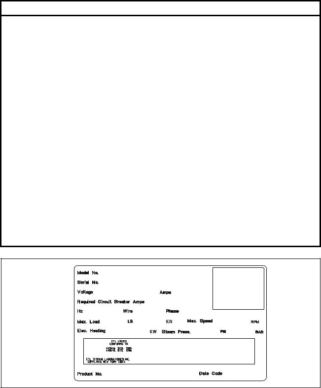
A record of each machine, including the serial number, is on file with the manufacturer. The serial number decal is located at the rear of the machine. See Figure 2. Always provide the machine’s serial number and model number when ordering parts or when seeking technical assistance.
12
F232062
Installation
Model Number Familiarization Guide
Sample Model Number: SC35MN2CU20001
SC |
Machine Type |
C = |
Cabinet |
|
|
|
|
|
|
35 |
Machine Capacity (pounds dry weight) |
|
|
|
|
|
|
|
|
M |
Type of Electrical Control |
M = |
Mechanical Timer |
|
(E) |
|
E = |
WX/EDC Microcomputer |
|
(P) |
|
P |
= |
P-Series Microcomputer† |
(S) |
|
S |
= |
S-Series Microcomputer |
(V) |
|
V = |
V-Series Microcomputer |
|
|
|
|
|
|
N |
Coin Meter Option |
N = |
No Coin Meter |
|
(C) |
|
C = |
W2000 (Computer-controlled models only)‡ |
|
(D) |
|
D = |
Digital (Mechanical Timer models only) |
|
(H) |
|
H = |
Horizontal Slide (Mechanical Timer models only) |
|
(V) |
|
V = |
Vertical Drop (Mechanical Timer models only) |
|
|
|
|
|
|
2 |
Speed |
2 |
= |
2-Speed |
(3) |
|
3 |
= |
3-Speed |
(V) |
|
V = |
Variable-Speed |
|
|
|
|
||
C |
Electrical Characteristics |
See Voltage Designation Chart in this section. |
||
|
|
|
|
|
U2 |
Design Series |
|
|
|
|
|
|||
0001 |
Option Identification (varies from machine to machine) |
|||
|
|
|
|
|
†Models designated “PN” use the S-Series Microcomputer.
‡Models designated “MC” are prepared for use with an aftermarket coin meter.
SC35MN2CU20001 |
|
|
00000000000 |
|
|
380 – 415 |
|
5 |
|
15 |
|
50 |
4 |
3 |
35 |
16 |
470 |
500000
H043I
Figure 2
13
F232062

Installation
Cabinet Hardmount General Specifications
2-Speed Models
Specification |
18 |
25 |
|
|
27 |
35 |
50 |
|
|
|
|
|
|
|
|
|
Overall Dimensions |
|
|
|
|
||
|
|
|
|
|
|
|
|
Overall width, in (mm) |
26 (660) |
26 (660) |
|
29 |
(737) |
30-1/8 (765) |
34-1/16 (865) |
|
|
|
|
|
|
|
|
Overall height, in (mm) |
42 (1067) |
45 (1143) |
|
45 (1143) |
47-1/4 (1200) |
49-3/4 (1265) |
|
|
|
|
|
|
|
|
|
Overall depth, in (mm) |
29-11/16 |
33-11/16 |
|
34-13/16 |
38-1/2 (978) |
42 (1067) |
|
|
(754) |
(856) |
|
(884) |
|
|
|
|
|
|
|
|
|
||
|
Weight and Shipping Information |
|
|
||||
|
|
|
|
|
|
|
|
Net weight, lb (kg) |
390 (177) |
435 (198) |
|
495 (225) |
650 (295) |
820 (373) |
|
|
|
|
|
|
|
|
|
Domestic shipping weight, lb (kg) |
430 (194) |
475 (214) |
|
555 (250) |
710 (320) |
970 (437) |
|
|
|
|
|
|
|
|
|
Domestic shipping volume, ft3 (m3) |
23.9 (0.669) |
28.9 (0.809) |
|
30.1 |
(0.852) |
39.0 (1.09) |
49.8 (1.39) |
|
|
|
|
|
|
|
|
Export shipping weight, lb (kg) |
480 (218) |
525 (236) |
|
605 (272) |
760 (345) |
1020 (464) |
|
|
|
|
|
|
|
|
|
Export shipping volume, ft3 (m3) |
47.1 (1.32) |
35.9 (1.01) |
|
37.7 (1.07) |
47.1 (1.32) |
68.6 (1.92) |
|
|
Wash Cylinder Information |
|
|
|
|||
|
|
|
|
|
|
|
|
Cylinder diameter, in (mm) |
21 (533) |
21 (533) |
|
24 |
(610) |
26-1/4 (667) |
30 (762) |
|
|
|
|
|
|
|
|
Cylinder depth, in (mm) |
13-3/4 (349) |
18-3/4 (457) |
|
16 |
(406) |
18-3/8 (467) |
20 (508) |
|
|
|
|
|
|
|
|
Cylinder volume, ft3 (l) |
2.76 (78.1) |
3.76 (106) |
|
4.19 |
(117.9) |
5.76 (163.1) |
8.18 (232) |
Perforation size, in (mm) |
0.188 (4.76) |
0.188 (4.76) |
|
0.188 (4.76) |
0.188 (4.76) |
0.188 (4.76) |
|
|
|
|
|
|
|
|
|
Perforation open area,% |
17 |
17 |
|
|
23 |
17 |
18 |
|
|
|
|
|
|
|
|
|
Door Opening Information |
|
|
|
|||
|
|
|
|
|
|
|
|
Door opening size, in (mm) |
12 (305) |
12 (305) |
|
14-11/32 |
13-15/16 |
16-1/4 (413) |
|
|
|
|
|
(364) |
(354) |
|
|
|
|
|
|
|
|
|
|
Ht. door bottom above floor, in |
17-1/4 (438) |
17-1/4 (438) |
|
17 |
(432) |
19 (480) |
18-1/4 (465) |
(mm) |
|
|
|
|
|
|
|
|
|
|
|
|
|
|
|
|
Power Consumption |
|
|
|
|
||
|
|
|
|
|
|
|
|
Avg. power used per cycle, kW/hr |
0.20 |
0.25 |
|
0.25 |
0.30 |
0.42 |
|
|
|
|
|
|
|
|
|
Nominal sound emission, dBA |
60 |
63 |
|
|
63 |
64 |
66 |
|
|
|
|
|
|
|
|
Background noise level, dBA |
48 |
51 |
|
|
51 |
49 |
49 |
|
|
|
|
|
|
|
|
Average HVAC load, Btu/hr |
425 |
400 |
|
400 est. |
510 |
700 |
|
|
|
|
|
|
|
|
|
14
F232062

Installation
Cabinet Hardmount General Specifications
2-Speed Models (Continued)
Specification |
|
18 |
25 |
|
27 |
35 |
50 |
|
|
|
|
|
|
|
|
|
|
Drive Train Information |
|
|
|
||
|
|
|
|
|
|
|
|
Number of motors in drive train |
1 |
1 |
|
1 |
1 |
1 |
|
|
|
|
|
|
|
|
|
Wash/reverse power, hp (kW) |
0.18 (0.13) |
0.25 (0.19) |
|
0.25 (0.19) |
0.40 (0.30) |
0.55 (0.41) |
|
|
|
|
|
|
|
|
|
High extract power, hp (kW) |
1.0 (0.746) |
1.4 (1.04) |
|
1.4 (1.04) |
1.8 (1.3) |
2.7 (2.01) |
|
|
|
|
|
|
|
|
|
|
|
Cylinder Speeds |
|
|
|
||
|
|
|
|
|
|
|
|
Wash/reverse speed, rpm |
|
53 |
55 |
|
47 |
47 |
44 |
|
|
|
|
|
|
|
|
High extract speed, rpm |
|
525 |
540 |
|
480 |
470 |
450 |
|
|
|
|
|
|
|
|
|
|
Centrifugal Force Data |
|
|
|
||
|
|
|
|
|
|
|
|
Wash/reverse centrifugal force, Gs |
0.85 |
0.90 |
|
0.75 |
0.82 |
0.825 |
|
|
|
|
|
|
|
|
|
High extract centrifugal force, Gs |
82.1 |
86.9 |
|
80 |
82.3 |
86.3 |
|
|
|
|
|
|
|
|
|
|
|
Balance Detection |
|
|
|
||
|
|
|
|
|
|
|
|
Vibration safety switch installed |
N/A |
N/A |
|
N/A |
N/A |
N/A |
|
|
|
|
|
|
|
|
|
|
|
Direct Steam Heating (Optional) |
|
|
|||
|
|
|
|
|
|
|
|
Steam inlet connection size, in (mm) |
1/2 (13) |
1/2 (13) |
|
1/2 (13) |
1/2 (13) |
1/2 (13) |
|
|
|
|
|
|
|
|
|
Number of steam inlets |
|
1 |
1 |
|
1 |
1 |
1 |
|
|
|
|
|
|
|
|
Steam req. to raise bath |
LOW |
1.1 (0.50) |
1.4 (0.64) |
|
1.5 (0.68) |
2.1 (0.95) |
2.8 (1.3) |
temperature 10°F, lb |
|
|
|
|
|
|
|
HIGH |
1.2 (0.54) |
1.6 (0.73) |
|
1.7 (0.77) |
2.8 (1.3) |
3.7 (1.7) |
|
(10°C, kg) |
|
||||||
|
|
|
|
|
|
|
|
Average steam use per cycle, BHP |
0.66 |
0.87 |
|
0.94 |
1.4 |
1.9 |
|
|
|
|
|
|
|
|
|
|
|
Electrical Heating (Optional) |
|
|
|||
|
|
|
|
|
|
|
|
Total electrical heating capacity, kW |
7.8 |
7.8 |
|
7.8 |
15.6 |
23.4 |
|
|
|
|
|
|
|
|
|
Electrical heating elements |
3 |
3 |
|
3 |
6 |
9 |
|
|
|
|
|
|
|
|
|
Electrical heat element size, kW |
2.6 |
2.6 |
|
2.6 |
2.6 |
2.6 |
|
|
|
|
|
|
|
|
|
15
F232062

Installation
Cabinet Hardmount General Specifications
3-Speed Models
Specification |
18 |
35 |
50 |
80 |
|
|
|
|
|
|
Overall Dimensions |
|
|
|
|
|
|
|
|
Overall width, in (mm) |
26 (660) |
30-1/8 (765) |
34-1/16 (865) |
41-1/2 (1054) |
|
|
|
|
|
Overall height, in (mm) |
42 (1067) |
47-1/4 (1200) |
49-3/4 (1265) |
56 (1422) |
|
|
|
|
|
Overall depth, in (mm) |
29-11/16 (754) |
38-1/2 (978) |
42 (1067) |
51-5/8 (1311) |
|
|
|
|
|
|
Weight and Shipping Information |
|
|
|
|
|
|
|
|
Net weight, lb (kg) |
400 (182) |
675 (307) |
950 (432) |
1600 (727) |
|
|
|
|
|
Domestic shipping weight, lb (kg) |
430 (195) |
780 (355) |
990 (450) |
1650 (743) |
|
|
|
|
|
Domestic shipping volume, ft3 (m3) |
23.9 (0.669) |
39.0 (1.09) |
49.8 (1.39) |
78.1 (2.19) |
|
|
|
|
|
Export shipping weight, lb (kg) |
490 (223) |
785 (357) |
1150 (523) |
1700 (765) |
|
|
|
|
|
Export shipping volume, ft3 (m3) |
47.1 (1.32) |
47.1 (1.32) |
68.6 (1.92) |
--- |
|
Wash Cylinder Information |
|
|
|
|
|
|
|
|
Cylinder diameter, in (mm) |
21 (533) |
26-1/4 (667) |
30 (762) |
36 (914) |
|
|
|
|
|
Cylinder depth, in (mm) |
13-3/4 (349) |
18-3/8 (467) |
20 (508) |
22 (559) |
|
|
|
|
|
Cylinder volume, ft3 (l) |
2.76 (78.1) |
5.76 (163.1) |
8.18 (232) |
12.4 (354) |
Perforation size, in (mm) |
0.188 (4.76) |
0.188 (4.76) |
0.188 (4.76) |
0.188 (4.76) |
|
|
|
|
|
Perforation open area,% |
17 |
17 |
18 |
--- |
|
|
|
|
|
|
Door Opening Information |
|
|
|
|
|
|
|
|
Door opening size, in (mm) |
12 (305) |
13-15/16 (354) |
16-1/4 (413) |
18-1/2 (470) |
|
|
|
|
|
Ht. door bottom above floor, in (mm) |
17-1/4 (438) |
19 (480) |
18-1/4 (465) |
21-1/2 (546) |
|
|
|
|
|
|
Power Consumption |
|
|
|
|
|
|
|
|
Avg. power used per cycle, kW/hr |
0.18 est |
0.28 est |
0.38 est |
0.55 est. |
|
|
|
|
|
Nominal sound emission, dBA |
61 |
65 |
67 |
60 / 69 |
|
|
|
|
|
Background noise level, dBA |
48 |
49 |
49 |
47 |
|
|
|
|
|
Average HVAC load, Btu/hr |
440 |
525 |
725 |
900 |
|
|
|
|
|
16
F232062

Installation
Cabinet Hardmount General Specifications
3-Speed Models (Continued)
Specification |
|
18 |
35 |
50 |
80 |
|
|
|
|
|
|
|
|
|
|
Drive Train Information |
|
|
||
|
|
|
|
|
||
Number of motors in drive train |
1 |
2 |
2 |
2 |
||
|
|
|
|
|
|
|
Wash/reverse power, hp (kW) |
|
0.18 (0.13) |
0.40 (0.30) |
0.90 ( 0.67) |
1.0 (0.75) |
|
|
|
|
|
|
||
Medium extract power, hp (kW) |
1.2 (0.895) |
0.45 (0.34) |
1.0 (0.75) |
1.2 (0.89) |
||
|
|
|
|
|
|
|
High extract power, hp (kW) |
|
1.5 (1.12) |
3.0 (2.2) |
3.5 (2.6) |
4.5 (3.36) |
|
|
|
|
|
|
|
|
|
|
Cylinder Speeds |
|
|
||
|
|
|
|
|
|
|
Wash/reverse speed, rpm |
|
46 |
47 |
44 |
40 |
|
|
|
|
|
|
|
|
Medium extract speed, rpm |
|
330 |
75 |
60 |
64 |
|
|
|
|
|
|
|
|
High extract speed, rpm |
|
661 |
591 |
561 |
530 |
|
|
|
|
|
|
|
|
|
|
Centrifugal Force Data |
|
|
||
|
|
|
|
|
||
Wash/reverse centrifugal force, Gs |
0.65 |
0.82 |
0.825 |
0.82 |
||
|
|
|
|
|
||
Medium extract centrifugal force, Gs |
32.5 |
2.10 |
1.53 |
2.1 |
||
|
|
|
|
|
||
High extract centrifugal force, Gs |
130 |
130 |
134 |
143 |
||
|
|
|
|
|
|
|
|
|
Balance Detection |
|
|
||
|
|
|
|
|
||
Vibration safety switch installed |
N/A |
Standard |
Standard |
Standard |
||
|
|
|
|
|
|
|
|
|
Direct Steam Heating (Optional) |
|
|
||
|
|
|
|
|
||
Steam inlet connection size, in (mm) |
1/2 (13) |
1/2 (13) |
1/2 (13) |
1/2 (13) |
||
|
|
|
|
|
|
|
Number of steam inlets |
|
1 |
1 |
1 |
1 |
|
|
|
|
|
|
|
|
Steam req. to raise bath |
LOW |
1.1 (0.5) |
2.1 (0.95) |
2.8 (1.3) |
4.4 (2.0) |
|
temperature 10°F, lb |
|
|
|
|
|
|
HIGH |
1.2 (0.54) |
2.8 (1.3) |
3.7 (1.7) |
6.3 (2.9) |
||
(10°C, kg) |
||||||
|
|
|
|
|
||
Average steam use per cycle, BHP |
0.66 |
1.4 |
1.9 |
3.1 |
||
|
|
|
|
|
|
|
|
|
Electrical Heating (Optional) |
|
|
||
|
|
|
|
|
||
Total electrical heating capacity, kW |
7.8 |
15.6 |
23.4 |
31.2 |
||
|
|
|
|
|
|
|
Electrical heating elements |
|
3 |
6 |
9 |
12 |
|
|
|
|
|
|
||
Electrical heat element size, kW |
2.6 |
2.6 |
2.6 |
2.6 |
||
|
|
|
|
|
|
|
17
F232062
Installation
|
|
Cabinet Hardmount General Specifications |
|
|||||
|
|
|
Variable-Speed Models |
|
|
|||
|
|
|
|
|
|
|
||
Specification |
18 |
27 |
|
35 |
50 |
80 |
||
|
|
|
|
|
|
|
|
|
|
|
|
Overall Dimensions |
|
|
|
||
|
|
|
|
|
|
|
||
Overall width, in (mm) |
26 (660) |
29 (737) |
|
30-1/8 (765) |
34-1/16 (865) |
41-1/2 (1054) |
||
|
|
|
|
|
|
|
||
Overall height, in (mm) |
42 (1067) |
45 (1143) |
|
47-1/4 (1200) |
49-3/4 (1265) |
56 (1422) |
||
|
|
|
|
|
|
|
||
Overall depth, in (mm) |
29-11/16 |
34-13/16 |
|
38-1/2 (978) |
42 (1067) |
51-5/8 (1311) |
||
|
|
|
(754) |
(884) |
|
|
|
|
|
|
|
|
|
|
|
|
|
|
|
|
Weight and Shipping Information |
|
|
|||
|
|
|
|
|
|
|
|
|
Net weight, lb (kg) |
|
|
404 (182) |
520 (234) |
|
640 (288) |
788 (355) |
1406 (633) |
|
|
|
|
|
|
|
||
Domestic shipping weight, lb (kg) |
424 (191) |
545 (245) |
|
670 (301) |
818 (371) |
1456 (655) |
||
|
|
|
|
|
|
|
||
Domestic shipping volume, ft3 (m3) |
23.9 (0.669) |
30.1 (0.852) |
|
39.0 (1.09) |
49.8 (1.39) |
96.18 (2.69) |
||
Export shipping weight, lb (kg) |
494 (222) |
610 (275) |
|
750 (338) |
988 (448) |
1506 (678) |
||
|
|
|
|
|
|
|
||
Export shipping volume, ft3 (m3) |
47.1 (1.32) |
37.7 (1.07) |
|
47.1 (1.32) |
68.6 (1.92) |
109.4 (3.1) |
||
|
|
|
Wash Cylinder Information |
|
|
|||
|
|
|
|
|
|
|
||
Cylinder diameter, in (mm) |
21 (533) |
24 (610) |
|
26-1/4 (667) |
30 (762) |
36 (914) |
||
|
|
|
|
|
|
|
||
Cylinder depth, in (mm) |
13-3/4 (349) |
16 (406) |
|
18-3/8 (467) |
20 (508) |
22 (559) |
||
|
|
|
|
|
|
|
|
|
Cylinder volume, ft |
3 |
(l) |
2.76 (78.1) |
4.19 (117.9) |
|
5.76 (163.1) |
8.18 (232) |
12.4 (354) |
|
|
|
|
|
|
|
||
|
|
|
|
|
|
|
||
Perforation size, in (mm) |
0.188 (4.76) |
0.188 (4.76) |
|
0.188 (4.76) |
0.188 (4.76) |
0.188 (4.76) |
||
|
|
|
|
|
|
|
||
Perforation open area,% |
17 |
23 |
|
17 |
18 |
27 |
||
|
|
|
|
|
|
|
|
|
|
|
|
Door Opening Information |
|
|
|||
|
|
|
|
|
|
|
||
Door opening size, in (mm) |
12 (305) |
14-11/32 |
|
13-15/16 |
16-1/4 (413) |
18-1/2 (470) |
||
|
|
|
|
(364) |
|
(354) |
|
|
|
|
|
|
|
|
|
||
Ht. door bottom above floor, in (mm) |
17-1/4 (438) |
17 (432) |
|
19 (480) |
18-1/4 (465) |
21-1/2 (546) |
||
|
|
|
|
|
|
|
|
|
|
|
|
Power Consumption |
|
|
|
||
|
|
|
|
|
|
|
||
Avg. power used per cycle, kW/hr |
0.11 |
0.14 |
|
0.20 |
0.37 |
|
||
|
|
|
|
|
|
|
||
Nominal sound emission, dBA |
N/A |
N/A |
|
N/A |
N/A |
N/A |
||
|
|
|
|
|
|
|
||
Background noise level, dBA |
N/A |
N/A |
|
N/A |
N/A |
N/A |
||
|
|
|
|
|
|
|
||
Average HVAC load, Btu/hr |
425 |
425 |
|
510 |
510 |
900 |
||
|
|
|
|
|
|
|
|
|
|
|
|
Drive Train Information |
|
|
|||
|
|
|
|
|
|
|
||
Number of motors in drive train |
1 |
1 |
|
1 |
1 |
1 |
||
|
|
|
|
|
|
|
||
Drive motor power, hp (kW) |
1 (0.75) |
1 (0.75) |
|
2 (1.5) |
2 (1.5) |
5 (3.7) |
||
|
|
|
|
|
|
|
|
|
18 |
|
|
|
|
|
|
|
|
F232062
Installation
Cabinet Hardmount General Specifications
Variable-Speed Models (Continued)
Specification |
|
18 |
27 |
|
35 |
50 |
80 |
|
|
|
|
|
|
|
|
|
|
Cylinder Speeds |
|
|
|
||
|
|
|
|
|
|
|
|
Gentle wash/reverse speed, rpm |
29 |
27 |
|
26 |
24 |
22 |
|
|
|
|
|
|
|
|
|
Wash/reverse speed, rpm |
|
52 |
48 |
|
46 |
43 |
40 |
|
|
|
|
|
|
|
|
Distribution speed, rpm |
|
82 |
77 |
|
73 |
68 |
63 |
|
|
|
|
|
|
|
|
Low extract speed, rpm |
|
366 |
343 |
|
328 |
307 |
280 |
|
|
|
|
|
|
|
|
Medium extract speed, rpm* |
534 |
500 |
|
478 |
447 |
408 |
|
|
|
|
|
|
|
|
|
High extract speed, rpm |
|
685 |
641 |
|
613 |
573 |
524 |
|
|
|
|
|
|
|
|
|
|
Centrifugal Force Data |
|
|
|
||
|
|
|
|
|
|
|
|
Gentle wash centrifugal force, Gs |
0.25 |
0.25 |
|
0.25 |
0.25 |
0.25 |
|
|
|
|
|
|
|
|
|
Wash/reverse centrifugal force, Gs |
0.8 |
0.8 |
|
0.8 |
0.8 |
0.8 |
|
|
|
|
|
|
|
|
|
Distribution centrifugal force, Gs |
2 |
2 |
|
2 |
2 |
2 |
|
|
|
|
|
|
|
|
|
Low extract centrifugal force, Gs |
40 |
40 |
|
40 |
40 |
40 |
|
|
|
|
|
|
|
|
|
Med. extract centrifugal force, Gs |
85 |
85 |
|
85 |
85 |
85 |
|
|
|
|
|
|
|
|
|
High extract centrifugal force, Gs |
140 |
140 |
|
140 |
140 |
140 |
|
|
|
|
|
|
|
|
|
|
|
Balance Detection |
|
|
|
||
|
|
|
|
|
|
|
|
Vibration safety switch installed |
N/A |
N/A |
|
Standard |
Standard |
Standard |
|
|
|
|
|
|
|
|
|
|
|
Direct Steam Heating (Optional) |
|
|
|||
|
|
|
|
|
|
|
|
Steam inlet connection size, in (mm) |
1/2 (13) |
1/2 (13) |
|
1/2 (13) |
1/2 (13) |
1/2 (13) |
|
|
|
|
|
|
|
|
|
Number of steam inlets |
|
1 |
1 |
|
1 |
1 |
1 |
|
|
|
|
|
|
|
|
Steam req. to raise bath |
LOW |
1.1 (0.50) |
1.4 (0.64) |
|
2.1 (0.95) |
2.8 (1.3) |
4.4 (2.0) |
temperature 10°F, lb |
|
|
|
|
|
|
|
HIGH |
1.4 (0.64) |
1.9 (0.86) |
|
2.7 (1.2) |
3.7 (1.7) |
6.3(2.9) |
|
(10°C, kg) |
|
||||||
|
|
|
|
|
|
|
|
Average steam use per cycle, BHP |
0.72 |
0.96 |
|
1.4 |
1.9 |
3.1 |
|
|
|
|
|
|
|
|
|
|
|
Electrical Heating (Optional) |
|
|
|||
|
|
|
|
|
|
|
|
Total electrical heating capacity, kW |
7.8 |
7.8 |
|
15.6 |
23.4 |
31.2 |
|
|
|
|
|
|
|
|
|
Electrical heating elements |
|
3 |
3 |
|
6 |
9 |
12 |
|
|
|
|
|
|
|
|
Electrical heat element size, kW |
2.6 |
2.6 |
|
2.6 |
2.6 |
2.6 |
|
|
|
|
|
|
|
|
|
*Medium extract speed is not available on Electronic Control (EC) models.
19
F232062

Installation
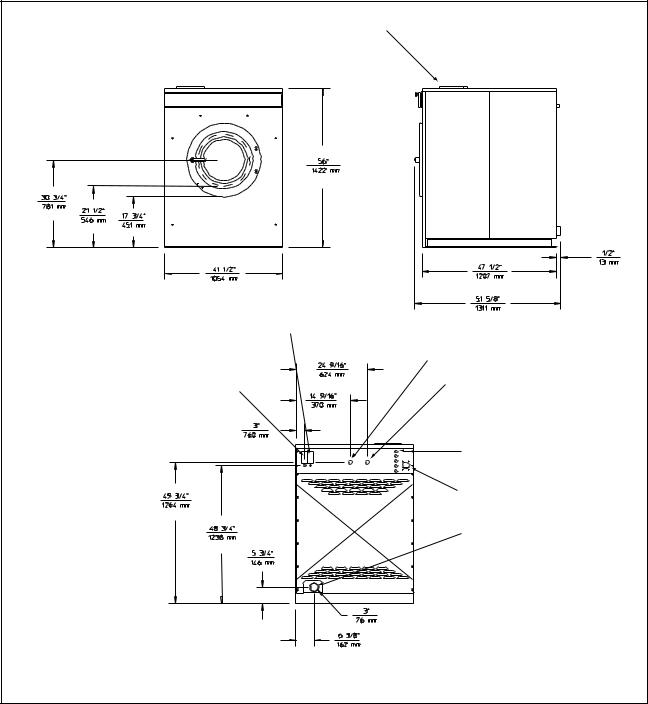
Machine Dimensions
Figures 3 through 8 illustrate the machine dimensions for each size of machine, starting with the 18-pound model and finishing with the 80-pound model.
Note: The dimensions shown are for planning purposes only. They are approximate and subject to normal manufacturing tolerances. If exact dimensions are required for construction purposes, contact the distributor or the manufacturer. We reserve the right to make changes at any time without notice.
20
F232062
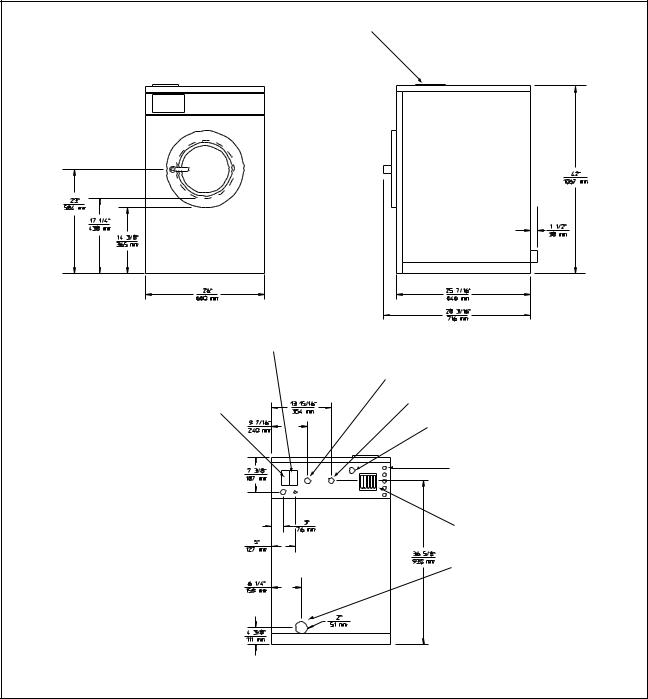
|
Installation |
|
Supply Dispenser |
|
|
External Chemical Supply Signal |
|
|
Terminal Strip (OPL only) |
Cold Water Inlet |
|
|
||
Input Power Block |
Hot Water Inlet |
|
Extra Water Inlet (optional) |
||
|
||
|
External Chemical |
|
|
Supply Inlets (OPL only) |
|
|
Vacuum Breaker |
|
|
Drain Outlet |
|
18-Pound Capacity Machines |
H001IE3A |
Figure 3
21
F232062
Installation
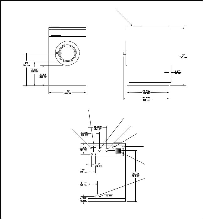
Machine Dimensions (Continued)
Supply Dispenser |
|
|
External Chemical Supply Signal |
|
|
Terminal Strip (OPL only) |
Cold Water Inlet |
|
|
||
Input Power Block |
Hot Water Inlet |
|
Extra Water Inlet (optional) |
||
|
||
|
External Chemical |
|
|
Supply Inlets (OPL only) |
|
|
Vacuum Breaker |
|
|
Drain Outlet |
|
25-Pound Capacity Machines |
H002IE3A |
Figure 4
22
F232062
|
Installation |
|
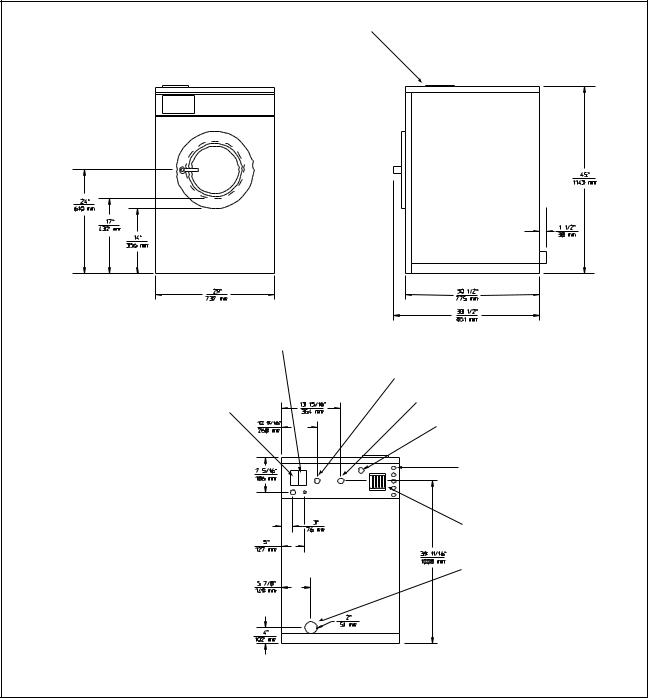
Supply Dispenser |
|
|
External Chemical Supply Signal |
|
|
Terminal Strip (OPL only) |
Cold Water Inlet |
|
|
||
Input Power Block |
Hot Water Inlet |
|
Extra Water Inlet (optional) |
||
|
||
|
External Chemical |
|
|
Supply Inlets (OPL only) |
|
|
Vacuum Breaker |
|
|
Drain Outlet |
|
27-Pound Capacity Machines |
H003IE3A |
Figure 5
23
F232062

Installation
Machine Dimensions (Continued)
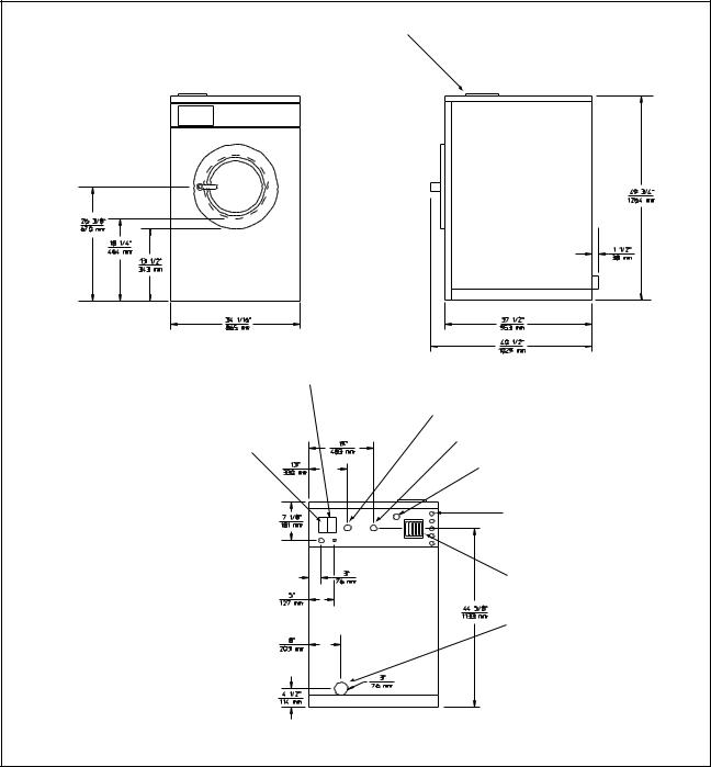
Supply Dispenser |
|
|
External Chemical Supply Signal |
|
|
Terminal Strip (OPL only) |
Cold Water Inlet |
|
|
||
Input Power Block |
Hot Water Inlet |
|
Extra Water Inlet (optional) |
||
|
||
|
External Chemical |
|
|
Supply Inlets (OPL only) |
|
|
Vacuum Breaker |
|
|
Drain Outlet |
|
35-Pound Capacity Machines |
H004IE3A |
Figure 6
24
F232062
|
Installation |
|
Supply Dispenser |
|
|
ExternalOPL on yChemical Supply Signal |
|
|
Terminal Strip (OPL only) |
Cold Water Inlet |
|
|
||
Input Power Block |
Hot Water Inlet |
|
Extra Water Inlet (optional) |
||
|
||
|
External Chemical |
|
|
Supply Inlets (OPL only) |
|
|
Vacuum Breaker |
|
|
Drain Outlet |
|
50-Pound Capacity Machines |
H005IE3A |
Figure 7
25
F232062
Installation
Machine Dimensions (Continued)
Supply Dispenser |
|
External Chemical Supply Signal |
|
Terminal Strip (OPL only) |
Cold Water Inlet |
|
|
Input Power Block |
Hot Water Inlet |
|
|
|
External Chemical |
|
Supply Inlets (OPL only) |
|
Vacuum Breaker |
|
Drain Outlet |
80-Pound Capacity Machines |
H049IE3A |
Figure 8
26
F232062
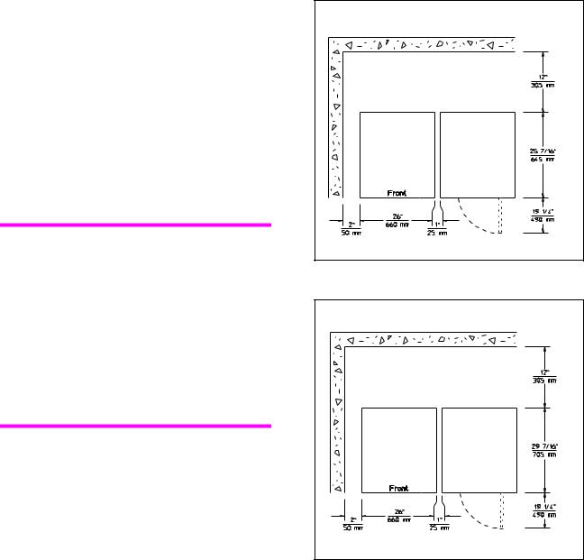
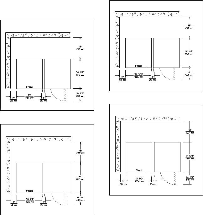
Dimensional Clearances
Allow a minimum of 12 inches (305 mm) at the rear for 18-pound and 25-pound capacity models and a minimum of 18 inches (457 mm) at the rear for the larger machines. Allow
2 inches (51mm) at the sides and 1 inch
(25 mm) between machines in multiple installations. Dimensional clearances are indicated in Figures 9 through 14 for each size of machine, starting with the 18-pound model and finishing with the 80-pound model.
Note: The dimensional clearances for the 80-pound model are dependent upon which set of mounting bolt holes is used. If the machine is intended for close mounting (mounting bolt pattern labeled "A" in Figure 28), follow the clearances in Figure 14. If the machine is intended for standard mounting (mounting bolt pattern labeled "B" in Figure 28), provide a minimum clearance of 8 inches (203 mm) at each side of the machine in addition to the clearances in Figure 14.
Installation |
18-Pound Capacity Machines |
H019IE1A |
Figure 9
25-Pound Capacity Machines |
H020IE1A |
Figure 10
27
F232062
Installation
Dimensional Clearances
(Continued) |
27-Pound Capacity Machines |
H021IE1A |
Figure 11
35-Pound Capacity Machines |
H022IE1A |
Figure 12
50-Pound Capacity Machines |
H023IE1A |
Figure 13
80-Pound Capacity Machines |
H048IE1A |
Figure 14
28
F232062
 Loading...