


ALESIS
X2
Reference Manual

Introduction
Thank you for purchasing the Alesis X2 24-channel, 8-group output, in-line monitor professional mixing console. To take full advantage of the X2’s functions, and to enjoy long and trouble-free use, please read this user’s manual carefully.
How To Use This Manual
This manual is divided into the following sections describing the various modules and functions of the X2. Though we recommend you take time to read through the entire manual once carefully, those having general knowledge about mixers should use the table of contents and index to reference specific functions while using the console.
Chapter 1: Introduction. Describes the various capabilities of the X2 and explains the basic principles of mixing and recording.
Chapter 2: Guided Tour. This section provides a brief tour of the X2, and shows you how particular features interact.
Chapter 3: Connections. Details rear panel connections (inputs, outputs, ADAT sync and audio interfaces, etc.), and their proper hook-up procedures.
Chapter 4: Applications. Covers the various uses for the X2 in different scenarios, with step-by-step instructions on setting up and mixing techniques.
Chapter 5: Mute Automation. Explains how to automate channel mutes using either the X2’s built-in sequencer or with an external MIDI sequencer.
Chapter 6: Description of Controls. A “dictionary” of each control.
Chapter 7: Trouble-shooting. A guide to trouble-free operation, maintenance and service information.
We have also included a block diagram, MIDI Implementation Chart and an Index.
Conventions
The buttons, knobs, and rear panel connectors are referred to in this manual just as their names appear on the X2, using all capital letters (Example: EQ IN switch, PAN knob, PHONES jack, etc.).
JWhen something important appears in the manual, an icon (like the one on the left) will appear in the left margin. This symbol indicates that this information is vital when operating the X2.
X2 Reference Manual |
1 |

2 |
X2 Reference Manual |

|
Contents |
CONTENTS |
|
1: Introduction ............................................................................................................ |
7 |
About the X2 ........................................................................................................................ |
7 |
Basic Principles of Mixing & Multitrack Recording ......................................................... |
8 |
Recording/Tracking .............................................................................................. |
8 |
Monitoring.............................................................................................................. |
8 |
Mixdown ................................................................................................................ |
9 |
2: Guided Tour............................................................................................................ |
11 |
Recorder/Mix Systems ....................................................................................................... |
11 |
Aux Send/Return Systems ................................................................................................. |
13 |
Control Room Systems........................................................................................................ |
14 |
Muting Automation............................................................................................................. |
14 |
Meter Bridge ........................................................................................................................ |
14 |
3: Connections ............................................................................................................ |
15 |
Unpacking and Inspection .................................................................................................. |
15 |
Power.................................................................................................................................... |
15 |
Power Supply ......................................................................................................... |
15 |
Avoiding Ground Loops ....................................................................................... |
17 |
Channel Inputs and Outputs .............................................................................................. |
18 |
Balanced Mic Inputs .............................................................................................. |
18 |
Unbalanced Line Inputs ........................................................................................ |
18 |
Tape Input .............................................................................................................. |
19 |
+4/-10 Switch ......................................................................................................... |
19 |
Tape Send (Direct Output).................................................................................... |
19 |
Insert ....................................................................................................................... |
19 |
Balanced Tape I/O................................................................................................. |
20 |
Stereo Returns and Groups................................................................................................. |
21 |
Group Outputs....................................................................................................... |
21 |
Group Inserts.......................................................................................................... |
21 |
Aux A & B Returns ................................................................................................ |
21 |
Master Inputs and Outputs................................................................................... |
22 |
Master Outputs ...................................................................................................... |
22 |
Master Inserts......................................................................................................... |
22 |
Control Room Outputs.......................................................................................... |
22 |
Studio Outputs....................................................................................................... |
22 |
External 1 & 2 Inputs ............................................................................................. |
22 |
Aux Sends............................................................................................................... |
22 |
Headphones............................................................................................................ |
23 |
ADAT Sync .......................................................................................................................... |
23 |
MIDI ..................................................................................................................................... |
23 |
Examples of Connections.................................................................................................... |
24 |
Interfacing to an Unbalanced -10 dBV Multitrack Recorder .............................. |
25 |
Interfacing to a Professional +4 dBu Multitrack Recorder ................................. |
26 |
Interfacing to a Multitrack Recorder via a Patchbay .......................................... |
27 |
Interfacing to ADAT Using ELCO Connectors ................................................... |
27 |
Interfacing to the Mixdown Deck......................................................................... |
27 |
Interfacing to the Control Room........................................................................... |
28 |
Interfacing to the Studio........................................................................................ |
28 |
X2 Reference Manual |
3 |

Contents
Interfacing to the Headphone Amp...................................................................... |
28 |
Interfacing Aux Sends and Returns to Outboard Effects ................................... |
28 |
Interfacing the Inserts ............................................................................................ |
29 |
Interfacing with a MIDI Sequencer ...................................................................... |
30 |
4: Applications ............................................................................................................ |
31 |
Recording ............................................................................................................................. |
31 |
Setting Levels ......................................................................................................... |
31 |
Recording a Single Source to One Track.............................................................. |
32 |
Recording Multiple Sources to One Track........................................................... |
33 |
Recording Multiple Sources to Two Tracks (Stereo)........................................... |
34 |
Recording Tips ....................................................................................................... |
35 |
About Metering...................................................................................................... |
35 |
Overdubbing........................................................................................................................ |
36 |
Monitoring the Multitrack on the Monitor Faders.............................................. |
36 |
Monitoring the Multitrack on the Channel Faders.............................................. |
36 |
Getting the Mix to the Headphones ..................................................................... |
37 |
Monitoring MIDI Virtual Tracks .......................................................................... |
37 |
Adding Effects........................................................................................................ |
38 |
Bouncing Tracks..................................................................................................... |
40 |
Playback/Mix-Down........................................................................................................... |
41 |
Mixdown Basics ..................................................................................................... |
41 |
Getting the Mix to the Tape Deck......................................................................... |
41 |
Creating a Dependable Mix .................................................................................. |
42 |
Mute Automation .................................................................................................. |
43 |
Live Performance................................................................................................................. |
44 |
Creating a Monitor Mix......................................................................................... |
44 |
Using Group Faders as Subgroups....................................................................... |
44 |
Stage Monitor Mix ................................................................................................. |
45 |
Video Post-Production ........................................................................................................ |
45 |
5: Mute Automation .................................................................................................... |
47 |
Overview.............................................................................................................................. |
47 |
Destructive Solo................................................................................................................... |
48 |
Mute Groups........................................................................................................................ |
48 |
Defining Mute Groups........................................................................................... |
49 |
Recalling Mute Groups.......................................................................................... |
50 |
OVERLAY Button .................................................................................................. |
50 |
Display.................................................................................................................................. |
51 |
Synchronization ................................................................................................................... |
51 |
Selecting a Sync Source.......................................................................................... |
51 |
Getting On-line/Locking....................................................................................... |
51 |
Mute Events ......................................................................................................................... |
52 |
Recording and Playing Back Mute Events........................................................... |
52 |
Undoing Mute Events............................................................................................ |
52 |
Overdubbing .......................................................................................................... |
52 |
Editing Songs ....................................................................................................................... |
53 |
Erasing .................................................................................................................... |
53 |
Erase All Memory .................................................................................................. |
54 |
Copying ................................................................................................................................ |
55 |
Copy Mute Events ................................................................................................. |
55 |
Copy Song .............................................................................................................. |
55 |
4 |
X2 Reference Manual |

|
Contents |
MIDI ..................................................................................................................................... |
56 |
MIDI Channel......................................................................................................... |
56 |
Selecting Songs via MIDI....................................................................................... |
56 |
MIDI Map ............................................................................................................... |
57 |
Memory Backup .................................................................................................................. |
58 |
Transmitting System Exclusive............................................................................. |
58 |
Receiving System Exclusive .................................................................................. |
58 |
Remaining Memory ............................................................................................... |
58 |
6: Description of Controls ........................................................................................... |
59 |
Input Channel Controls....................................................................................................... |
59 |
+48 V Switch........................................................................................................... |
59 |
Mic/Line Switch .................................................................................................... |
59 |
PHASE (Ø) Switch ................................................................................................. |
59 |
Mic/Line Gain........................................................................................................ |
59 |
Chan/Mon Reverse ............................................................................................... |
59 |
HPF Switch ............................................................................................................. |
60 |
Hi and Lo EQ ......................................................................................................... |
60 |
TO MON Switch .................................................................................................... |
60 |
Hi Mid and Lo Mid EQ ......................................................................................... |
60 |
EQ IN Switch.......................................................................................................... |
60 |
AUX 1–2, AUX 1–2 PAN ....................................................................................... |
61 |
AUX 3/7 and AUX 4/8 ......................................................................................... |
61 |
7/8 Switch (Aux 3/4)............................................................................................. |
61 |
AUX SOURCE Switch ........................................................................................... |
61 |
AUX 5/7 and AUX 6/8 ......................................................................................... |
61 |
7/8 Switch (Aux 5/6)............................................................................................. |
61 |
Monitor PAN.......................................................................................................... |
62 |
Monitor PEAK LED............................................................................................... |
62 |
Monitor SOLO Button ........................................................................................... |
62 |
Monitor MUTE Button .......................................................................................... |
62 |
Monitor L-R Button ............................................................................................... |
62 |
Monitor Fader ........................................................................................................ |
62 |
Channel PAN ......................................................................................................... |
62 |
Channel PEAK LED............................................................................................... |
63 |
Channel SOLO Button ........................................................................................... |
63 |
Channel MUTE Button .......................................................................................... |
63 |
DIR Switch.............................................................................................................. |
63 |
Group Assign Switches (1–2, 3–4, 5–6, 7–8) ......................................................... |
63 |
Channel L-R Button ............................................................................................... |
63 |
Channel Fader ........................................................................................................ |
64 |
Aux Master Controls........................................................................................................... |
64 |
Aux Send Levels .................................................................................................... |
64 |
AFL (After-Fader-Listen) Buttons ........................................................................ |
64 |
MUTE Buttons........................................................................................................ |
64 |
Stereo Aux Return Controls................................................................................................ |
64 |
Level........................................................................................................................ |
64 |
Hi and Lo EQ ......................................................................................................... |
64 |
PEAK LED.............................................................................................................. |
65 |
Stereo Separation ................................................................................................... |
65 |
Balance .................................................................................................................... |
65 |
TO AUX 1–2 Level ................................................................................................. |
65 |
X2 Reference Manual |
5 |

Contents
AUX A ASSIGN Switches (Aux A Only) ............................................................. |
65 |
GROUP MASTERS Switch (Aux B Only) ............................................................ |
65 |
L-R Button .............................................................................................................. |
65 |
SOLO Button .......................................................................................................... |
65 |
MUTE Button ......................................................................................................... |
66 |
Group Master Controls ....................................................................................................... |
66 |
ASSIGN LEFT ........................................................................................................ |
66 |
ASSIGN RIGHT ..................................................................................................... |
66 |
PFL (Pre-Fader-Listen) Button .............................................................................. |
66 |
MUTE Buttons........................................................................................................ |
66 |
Group 1—8 Master Faders .................................................................................... |
66 |
Master Controls ................................................................................................................... |
67 |
Oscillator Frequency and Level ............................................................................ |
67 |
SOLO LED and Level ............................................................................................ |
67 |
Studio Level and Assignment............................................................................... |
67 |
Talkback Level and Assignment........................................................................... |
67 |
Phones..................................................................................................................... |
68 |
Control Room Level and Source........................................................................... |
68 |
DIM ......................................................................................................................... |
68 |
MONO .................................................................................................................... |
68 |
Master Faders......................................................................................................... |
68 |
Meter Bridge........................................................................................................... |
68 |
Mute Automation Controls ................................................................................................ |
69 |
DISPLAY................................................................................................................. |
69 |
INC & DEC............................................................................................................. |
69 |
SONG...................................................................................................................... |
69 |
SYNC....................................................................................................................... |
69 |
CHANNEL ............................................................................................................. |
69 |
MAP ........................................................................................................................ |
69 |
MUTE GROUPS..................................................................................................... |
70 |
DEFINE................................................................................................................... |
70 |
ALL/ALT ............................................................................................................... |
70 |
OVERLAY .............................................................................................................. |
70 |
ONLINE.................................................................................................................. |
71 |
UPDATE ................................................................................................................. |
71 |
UNDO..................................................................................................................... |
71 |
Copy Song .............................................................................................................. |
72 |
ERASE FWD and ERASE BWD Buttons.............................................................. |
72 |
ERASE SONG......................................................................................................... |
72 |
Memory Remaining ............................................................................................... |
72 |
SYS EX..................................................................................................................... |
73 |
Mute Solo................................................................................................................ |
73 |
7: Trouble-Shooting .................................................................................................... |
75 |
Trouble-Shooting Index ...................................................................................................... |
75 |
Checking the Software Version .......................................................................................... |
75 |
Re-initializing....................................................................................................................... |
75 |
Maintenance/Service .......................................................................................................... |
76 |
MIDI Maps Index........................................................................................................ |
79 |
Maps 1.1—1.3....................................................................................................................... |
79 |
Map 1.4 ................................................................................................................................. |
80 |
6 |
X2 Reference Manual |

|
Contents |
Maps 2.0—2.9....................................................................................................................... |
81 |
MIDI Implementation Chart ........................................................................................ |
82 |
Specifications .............................................................................................................. |
83 |
Internal Connector Pinouts................................................................................................. |
86 |
Block Diagram ..................................................................................................................... |
77 |
Index........................................................................................................................... |
88 |
X2 Reference Manual |
7 |

Introduction
CHAPTER 1
INTRODUCTION
About the X2
The X2 is an extremely flexible, 24-channel, 8-group output, in-line monitor professional mixing console. The monitor path of each channel has its own 45mm linear fader, automated mute, and access to EQ and Aux sends, so you can mix or monitor one input while the main path mixes another. This flexible design allows full mix control of 48 sources, plus 16 aux returns, for a total of 64 sources at mixdown. For this reason, the X2 is perfectly suited for professional project studios with a large number of MIDI sequencer-controlled sources that are synchronized with 24 tracks of ADAT.
Each channel features a high-quality 4-band equalizer with two midrange bands that are fully parametric, not just sweep EQ. The midrange Q (bandwidth) can be set as narrow as 1/6th of an octave, or as wide as several octaves, for boosting or cutting any frequency range desired. The two shelving bands may be split from the main channel path and switched into the monitor path. An EQ IN/OUT switch permits the entire EQ circuit to be bypassed when desired, maintaining the minimum signal path. A switchable high-pass filter removes low frequency rumble and noise. The EQ section uses film capacitors in a gyrator filter design, with plenty of headroom available so that boosting a band doesn’t cause distortion.
The X2 uses fully balanced +4 dBu inputs and outputs on 1/4" jacks, plus three 56pin ELCO® multipin connectors for quick, reliable +4 dBu balanced connection direct to the ELCO connector on each ADAT. The X2 may also be interfaced with - 10 dBV level unbalanced equipment. A DIRECT switch on each channel connects the Direct Out (instead of the corresponding Group Out) to the channel’s Tape Out jack, so that simultaneous 24-track recording is possible without repatching.
All 24 channels have a high-quality, low noise balanced microphone preamp with individually switchable 48 V phantom power for condenser microphones. Each input channel is individually modular, using glass epoxy circuit boards. The 24/8/2 meter bridge is integral, not an optional add-on. It provides peak metering on each channel, group and the stereo master outputs.
Effects and headphone mixes are handled by 8 Aux sends. Aux 1–2 is a pre-fader, pre-mute, stereo send that can be used to provide a cue mix from either the main or monitor path; Auxes 3–8 are post-fader intended for effects sends. Eight Stereo Aux Returns are provided, each with its own 2-band EQ, Stereo Separation control, Solo switch, and automated Mute. Returns may be routed to the stereo mix, the groups, and the cue mix, so that effects can be added to the final mix, printed to multitrack, monitored on headphones, or any combination desired. The X2 provides insert points on each channel, each group, and the stereo master for use with compressors and graphic equalizers.
Alesis Dynamic Mute Automation™ is built-in, providing control of 72 mute points
X2 Reference Manual |
9 |
Introduction
in the console (each channel, monitor, effect return, aux send, and group output). It features its own ADAT Synchronization Interface jack, plus MIDI in/out jacks, so that its built-in 10,000-event sequencer can be synchronized directly to the ADAT system or to a MIDI system. The mutes may be externally controlled by a MIDI sequencer, or, in live applications, by using 100 sets of four mute groups.
Control room monitoring is made simpler by stereo-in-place Solo on each main channel, monitor channel, and aux return. Each aux master and group may be previewed in the control room while leaving the rest of the signal path undisturbed. Studio outputs, a built-in talkback mic and three-frequency oscillator provide the necessary facilities for complete communication between engineer and artist.
Basic Principles of Mixing & Multitrack Recording
The function of the X2 Mixer, or any recording console for that matter, is to provide control of volume, tone and spatial positioning of signals from microphones, electronic instruments, and tape machines, and then to route these signals to a monitor system and tape recorder so they can be recorded and heard. Before the introduction of multitrack tape recorders, these signals had to be mixed together as a live performance. If the desired performance wasn’t correct because of a musical mistake or mixing problem, the performance had to be recorded again and again until the performance was deemed satisfactory.
The introduction of multitrack tape machines has changed this recording method forever. Most recording today has evolved into a multi-step process, including:
Recording/Tracking
Instead of needing an entire musical group to come together in order to capture a live performance, recordings can be made one instrument at a time and pieced together in a building block fashion. With the advent of drum machines and sequencers (such as the Alesis HR-16, HR-16:B, SR-16 and MMT-8), it is possible to build an entire song using “virtual” tracks before ever having to record onto tape.
Using this method of recording an instrument at a time allows for fixing mistakes (normally called “punching in”) of an incorrectly played part. By “punching in,” or replacing, the misplayed part, you can record a performance over and over again until it’s perfect.
Monitoring
In order to properly record a performance, both the engineer, producer and all of the players must be able to hear the performance. When listening to the speakers in a control room (where the mixer is), this is called monitoring; when the musicians are listening to headphones while overdubbing, this is called cueing. Adjustments to monitor or cue mixes should not affect the mix going to the recorder, so that recording levels remain at the optimum, even if the performer requires less of a particular instrument in the headphones.
Monitoring is a more complex operation than it might seem at first, since there are many mixes that occur simultaneously. Often there are 3 separate mixes (sometimes
10 |
X2 Reference Manual |

Introduction
more) happening simultaneously in order to complete the task of overdubbing. The comprehensive systems and logical layout of the X2 Mixer will make it relatively easy for you to accommodate even the most complex monitoring requirements. The following are a few of the typical mixes that may occur during a session:
•Multitrack Mix: The first mix would be the mix that is being recorded onto tape. This mix is derived from the Channel Faders and the Tape Outs or the Group Outs. These levels are nominally adjusted so that the optimum signal level reaches tape in order to ensure the least amount of noise or distortion. This level averages about 0 VU on the meters of an analog multitrack tape machine, or -15 dB on the inserts of a digital multitrack tape machine, such as the Alesis ADAT. However, the transient peaks of instruments such as percussion may exceed this average level by 10 to 15 dB. One of the key factors in setting the proper mix for the recorder is being aware of the headroom available on the tape, and making sure it isn’t exceeded.
•Monitor Speaker (Control Room) Mix: If you were to listen only to the multitrack mix, you would probably find that it would be terribly out of balance since the optimum recording level (the primary concern of a multitrack mix) is not necessarily the best listening level. Therefore, a second mix is required called the monitor mix, which provides the engineer with a useful instrument balance and enables him or her to make changes and adjustments to the mix (such as muting or soloing channels) without disturbing the signals being recorded on tape.
•Cue Mix: Many times a third separate mix is required which is sent to the musicians’ headphones for overdubbing. This is called the cue mix. This mix can be radically different from what the engineer is listening to (the monitor mix), since the musicians may need certain instruments either played louder or removed from the mix in order to hear their cues (hence the name “cue mix”). This mix is derived from the Pre-Fader Sends, so that the headphone mix will not change if the engineer makes fader adjustments to the monitor mix. Since the X2 Mixer has two Pre-Fader Aux Sends (Aux 1-2), either 2 separate mono cue mixes or 1 stereo cue mix may be created.
Mixdown
After all the desired musical parts have been performed and recorded satisfactorily, the mixdown stage takes place. During this stage, the musical parts are blended together, tonally enhanced with EQ and effects, positioned in the desired stereo spectrum with the PAN controls, and finally recorded onto a mixdown tape deck (such as a DAT machine, 2-Track reel-to-reel or cassette recorder, or 2 tracks of an ADAT). During mixdown, the engineer should be hearing the exact same mix the recorder is receiving. For this purpose, the Control Room section of the X2 provides two independent pairs of stereo External Inputs for listening to the playback from the mixdown tape deck.
X2 Reference Manual |
11 |

Introduction
12 |
X2 Reference Manual |

Guided Tour
CHAPTER 2:
GUIDED TOUR
Recorder/Mix Systems
The X2 is designed to be extremely flexible, as evidenced by the channel module design. This is where signals are mixed, EQ’d and routed to the Aux sends, Groups and Left and Right Master outs. Each channel provides a Tape In connector, where signals return from the multitrack recorder. These can be routed to either the main or monitor section of the channel. This allows you to mix a signal and monitor a tape signal simultaneously. If you also count the Aux returns, you have a total of 64 inputs. These can all be mixed down to a master tape deck via the L-R Master outs.
Let’s trace the signal flow from beginning to end. Note that the controls from top to bottom of each channel are not placed in the same order as they appear in the signal flow. To see the paths of the signal flow, refer to the block diagram accompanying this manual.
Each input module has three possible sources (line, mic and tape in) and two paths (the main channel and the monitor). First, the signal arrives at either the line or mic input of a channel; you choose one of these using the MIC/LINE switch. If using the mic input with a condenser microphone, the +48 V switch should be turned on to provide phantom power. If necessary, the Ø (phase) switch can be used to invert the signal’s phase. Next we come to the MIC/LINE GAIN knob, which is used to set the initial level of the signal. It is important to set this level properly, since high levels could lead to distortion and too low levels will cause noise (see Setting Levels).
Each channel features an in-line monitor which sends either the tape return or the input source to the L-R Master mix for monitoring. If we want to swap the inputs between the main channel and the monitor, we just press the CHAN/MON REVERSE button; now the tape returns are on the main channel while the normal
X2 Reference Manual |
13 |

Guided Tour
input appears at the monitor controls. This is the position normally used for mixdown (with the main channel assigned to L-R) or for bouncing tracks (with the main channel assigned to the appropriate Group or Groups). To avoid low-end rumble and noise, turn on the HPF (high-pass filter), which removes frequencies below 75 Hz.
Next we have the EQ section, which is broken into two groups: the Hi & Lo EQ, and the Hi Mid & Lo Mid EQ. The Hi & Lo EQ are shelf types, nested at 12 kHz and 80 Hz, respectively, with an adjustable gain of ±15 dB. These act much like the bass and treble knobs found on a typical amplifier. They can be assigned to the monitor path by pressing the TO MON switch located between the two knobs. The Hi Mid & Lo Mid EQ are true parametric types, with a sweepable bandwidth of 650 Hz to 15 kHz and 45 Hz to 950 Hz, respectively, with an adjustable gain of ±15 dB. The Q control adjusts how wide an area around the selected frequency should be cut or boosted, allowing you to be extremely specific about how you tailor your sound.
We’ll get back to the Aux Sends in a moment. Now let’s jump down to the Monitor section. Normally, this is where you can mix your tape returns. Here you have a PAN knob, SOLO and MUTE buttons, and a fader for controlling the monitor level. The PEAK LED will light momentarily whenever the monitor’s signal gets too hot. The L-R button lets you assign the monitor signal to the Master outputs. If you’re not using the monitor, leave this button turned off.
Finally, at the bottom of each channel we find the channel’s fader, PAN knob, SOLO and MUTE buttons, PEAK LED, and a set of buttons that let you determine the routing of the channel’s signal, and what signal the TAPE OUT jacks of the channel will receive. DIR selects the source of the TAPE OUT jacks of the channel strip: either the direct output of the channel itself (for recording a single source to a track) or the Group that is normally connected to that TAPE OUT (Group 1 in channels 1, 9, 17; Group 2 in channels 2, 10, 18; etc.). The assignment switches below DIR can route the channel’s signal to any of the eight Groups and to the L-R Master.
Once signals are routed to the Group section, you can use the Group faders to determine the total volume of all channels assigned there. Each Group module has its own set of SOLO and MUTE buttons. In the studio, the Group output usually is connected to the inputs of a multitrack recorder, such as the Alesis ADAT via the TAPE OUT jacks. During mixdown, the Groups may be “subgrouped” or assigned to the L-R Master mix, so that the Group modules can be used to adjust the master volume of like signals, such as multiple channels of drums or vocals. Using the ASSIGN L and ASSIGN R buttons, the Group signal can be routed back to the Master outputs. In live performance applications, the Group Out jacks may be used to feed other amplifiers, broadcast feeds or recorders where multiple mixers are required.
14 |
X2 Reference Manual |

Guided Tour
Aux Send/Return Systems
In the center of each channel module is the Aux Sends section, which allows the signal to be routed to outboard signal processing equipment or to feed a headphone amplifier. The first two sends (Aux 1-2) are Pre-Fader, meaning that the signal level is independent of the channel’s fader. These are ideal for headphone mixing of tape tracks for the musicians in the studio. Aux 3 through 8 are post fader, ideal for routing signals to reverb and other effects devices. Aux Sends 3-4 and 5-6 can be reassigned to Aux 7-8, using the 7/8 switch between either pair of knobs. You can route either the Channel’s signal or the Monitor’s signal to Aux Sends 1 through 4, by using the AUX SOURCE switch. In the Master module you’ll find master level controls for all 8 Aux Sends, along with individual SOLO and MUTE buttons.
The Aux Returns, found at the top of the Group section, are designed for routing the signals back from signal processing equipment. Aux Returns can be thought of as input channels without microphone inputs. They have most of the same routing capabilities of a channel. Each of the four Group modules provides two stereo returns with PEAK LEDs and controls for Hi & Lo EQ, Stereo Separation and Balance, SOLO and MUTE buttons, and output routing. Additionally, you can route each return to Aux 1-2 if you want your headphone mix to include the effects returns.
If you are using a MIDI system with several keyboards, each with stereo signals, you can alternatively use the Aux Returns as additional line inputs. This is especially useful for keyboards that provide their own on-board signal processing, and therefore do not need to be routed to the other Aux Sends.
X2 Reference Manual |
15 |

Guided Tour
Control Room Systems
A three-frequency oscillator, with adjustable level, allows you to record test tones onto your tapes. Below the Aux Masters section, level controls are available for Studio outputs, Headphone outputs and the Control Room outputs. The Control Room can selectively monitor the Master outputs (L-R), AUX 1-2, or External inputs 1 and 2 (EXT IN 1/EXT IN 2); these last two inputs are useful for signals returning from mix-down tape decks. The STUDIO outputs may receive signal either from Aux 1-2, or the same signal the Control Room is listening to, plus the Talkback from the internal microphone. The DIM button takes down the Control Room level by a significant amount (in case the studio phone rings while listening to a mix). Press the MONO button when you want to hear how a mix will sound in a ‘57 Chevy. The built-in talkback mic has its own adjustable level and may be routed to the Group outs (for slating the tape) and/or the Studio outputs. Finally, the Master output faders, which set the overall level of the stereo mix, are found at the bottom of the module.
Muting Automation
The Master module comes complete with X2 Dynamic Mute Automation™. The display and accompanying controls let you record each individual press of a MUTE button anywhere on the console into the internal mute automation sequencer, synchronized to incoming ADAT Sync, MIDI Time Code or a MIDI Clock. Four Mute Groups, which allow you to mute as many channels as you want with a single button press, are available in each of the 100 sequencer memory locations. Alternatively, these mute groups or individual mutes can be triggered remotely via MIDI or recorded into a MIDI sequencer.
Meter Bridge
The meter bridge provides a total of thirty-four 15-segment LED peak meters for the 24 Channels, 8 Groups and the two Master Outs (L-R). The 24 Channel meters can monitor either the Tape Send levels or the Tape Returns levels. To select the meter bridge mode, hold the ALL (ALT) button and press DISPLAY (METER BRIDGE).
16 |
X2 Reference Manual |

Guided Tour
This toggles the meters between Tape Sends and Tape Returns. Two Mode LEDs on the meter bridge indicate which mode is selected.
X2 Reference Manual |
17 |

Connecting the X2
CHAPTER 3:
CONNECTIONS
Unpacking and Inspection
Your X2 was packed carefully at the factory, and the container was designed to protect the unit during shipping. Please retain this container in the highly unlikely event that you need to return the X2 for servicing.
Upon receiving the X2, carefully examine the shipping carton and its contents for any sign of physical damage that may have occurred in transit. If you detect any damage, do not destroy any of the packing material or the carton, and immediately notify the carrier of a possible claim for damage. Damage claims must be made by you. Contact your Alesis dealer.
The shipping carton should contain the following items:
•This instruction manual
•Alesis X2 with the same serial number as shown on shipping carton
•X2 Power Supply unit
•AC Power Cable
•Alesis warranty card
JIt is important to register your purchase; if you have not already filled out your warranty card and mailed it back to Alesis, please take the time to do so now.
Power
Power Supply
The X2 external power supply works with any standard line voltage (100 to 240V, 50 to 60 Hz), and comes with a line cord suitable for the destination to which the mixing console is shipped.
The power supply should be placed within easy reach of the console, but not directly underneath it. However, do not mount it directly over unshielded audio equipment, to avoid electromagnetically inducing hum in such units.
The power supply comes with two cables. The first is a multi-pin adapter cable which connects between the power supply unit and the back panel of the X2. Do not use any multipin cable between the power supply unit and the X2 except that provided with the unit. Mount the power supply in an area with proper ventilation.
The second cable is a IEC-spec AC power cable (do not substitute any other AC cord), which is designed to be connected to an outlet that includes three pins, with the third, round pin connected to ground. The ground connection is an important safety feature designed to keep the chassis of electronic devices such as the X2 at ground potential. Unfortunately, the presence of a third pin does not always
X2 Reference Manual |
19 |
Connecting the X2
indicate that an outlet is properly grounded. You may use an AC line tester to determine this. If the outlet is not grounded, consult with a licensed electrician. When AC currents are suspected of being highly unstable in VAC and Hz, a professional power conditioner should be used.
To connect the power supply to the X2:
1Screw on one end of the multipin cable to the X2’s POWER connector, and the other end to the same type connector on the back of the power supply unit.
You will find the X2’s power supply connector on the left side of the rear panel.
2Attach the female end of the AC power cord to the power supply unit and the male end to a good quality, noise-free AC power source of the proper rating.
3To apply power to the X2, switch on the POWER switch of the power supply unit, so that it is in the | (on) position.
JDo not operate any electrical equipment with ungrounded outlets. Plugging the X2 into an ungrounded outlet, or “lifting” the unit off ground with a three-to-two wire adapter, can create a hazardous condition.
JAlesis cannot be responsible for problems caused by using the X2 or any associated equipment with improper AC wiring.
20 |
X2 Reference Manual |

Connecting the X2
Avoiding Ground Loops
In today’s studio, where it seems every piece of equipment has its own computer chip inside, there are many opportunities for ground loop problems to occur. These show up as hums, buzzes or sometimes radio reception and can occur if a piece of equipment “sees” two or more different paths to ground. While there are methods to virtually eliminate ground loops and stray radio frequency interference, most of the professional methods are expensive and involve installing a separate power source just for the sound system. Alternatively, here are some easy helpful hints that a professional studio installer might use to keep those stray hums and buzzes to a minimum.
1KEEP ALL ELECTRONICS OF THE SOUND SYSTEM ON THE SAME AC ELECTRICAL CIRCUIT. Most stray hums and buzzes happen as a result of different parts of the sound system being plugged into outlets of different AC circuits. If any noise generating devices such as air conditioners, refrigerators, neon lights, etc., are already plugged into one of these circuits, you then have a perfect condition for stray buzzes. Since most electronic devices of a sound system don’t require a lot of current (except for power amplifiers), it’s usually safe to run a multi-outlet box or two from a SINGLE wall outlet and plug in all of the components of your system there.
2KEEP AUDIO WIRING AS FAR AWAY FROM AC WIRING AS POSSIBLE. Many hums come from audio cabling being too near AC wiring. If a hum occurs, try moving the audio wiring around to see if the hum ceases or diminishes. If it’s not possible to separate the audio and AC wiring in some instances, make sure that the audio wires don’t run parallel to any AC wire (they should only cross at right angles, if possible).
3TO ELIMINATE HUM IF THE ABOVE HAS FAILED:
A)Disconnect the power from all outboard devices and tape machines except for the X2 mixer and control room monitor power amp.
B)Plug in each tape machine and outboard effects device one at a time. If possible, flip the polarity of the plug of each device (turn it around in the socket) until the quietest position is found.
C)Make sure that all of the audio cables are in good working order. Cables with a detached ground wire will cause a very loud hum!!
D)Keep all cables as short as possible, especially in unbalanced circuits.
If the basic experiments don’t uncover the source of the problem, consult your dealer or technician trained in proper studio grounding techniques. In some cases, a “star grounding” scheme must be used, with the X2 at the center of the star providing the shield ground on telescoping shields, which do NOT connect to the chassis ground of other equipment in the system.
X2 Reference Manual |
21 |
Connecting the X2
Channel Inputs and Outputs
Each of the 24 channel modules on the X2 contains an XLR balanced MIC Input connector, a 1/4" TRS balanced LINE Input jack, a 1/4" TRS balanced TAPE IN jack with a +4/-10 level switch, an unbalanced 1/4" TAPE SEND jack, and a TRS 1/4" INSERT jack. Also included are three 56-pin ELCO connectors which provide eight channels each of BALANCED TAPE Ins and Outs. Here are more detailed descriptions of each of these, and what they should be connected to.
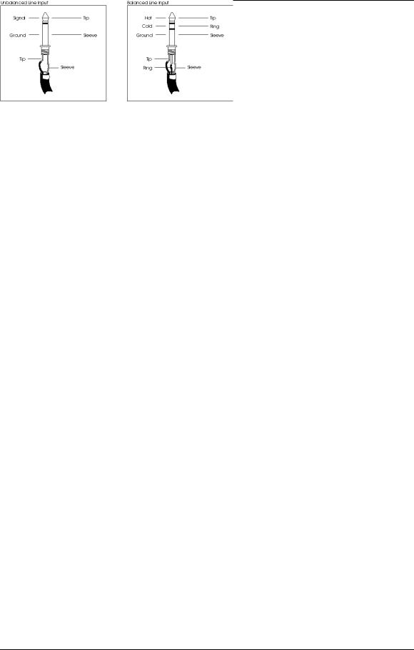
Balanced Mic Inputs
The MIC Input is a standard female XLR-3 connector and is available when the MIC/LINE switch is in the MIC (out) position (see section 6.0.2). The cable wiring is illustrated below
The MIC Input is designed to accept a wide range of balanced or unbalanced low impedance input signals. Each Mic input can provide the +48V necessary for phantom-powered microphones on pins 2 and 3; this may be turned on and off with the [+48V] switch (see section 6.0.1). The phase of pins 2 and 3 may be reversed using the [Ø] (phase) switch.
Unbalanced Line Inputs
The LINE Input is a 1/4" socket which will accept unbalanced or balanced line level sources when the MIC/LINE switch (see section 6.0.2) is in the LINE position.
Unlike the low impedance microphone input, this connection provides a high impedance (>10k ) to the input signal, enabling many types of instruments to be plugged straight in without direct boxes or external preamplification. While the output of a standard synthesizer (or other equipment) can be plugged in using a 2- conductor 1/4" plug, balanced line sources may also be connected here using a “stereo” TRS plug as shown above.
Line inputs may also be used for connecting additional effects returns, where
22 |
X2 Reference Manual |

Connecting the X2
additional post-effect equalization is required.
X2 Reference Manual |
23 |

Connecting the X2
Tape Input
The Tape Input is a 1/4" balanced TRS connector which will accept either -10 dBV or +4 dBu, depending on the setting of the +4/-10 switch (see next section). The Tape Input is the normal source of the Monitor path. However, when the CHAN/MON REVERSE switch is pressed, the Tape Input is switched over to the Channel path (see section 6.0.5). Connect the outputs of your balanced or unbalanced multitrack tape machine here; however, this jack is normally intended for use with unbalanced inputs, since the ELCO-type connector provides an easier way of connecting balanced tape inputs and outputs.
If you don’t use all the Tape Inputs, unused jacks may also be connected to the outputs of synthesizers or effects devices.
+4/-10 Switch
The +4/-10 switch adjusts the input level of the Tape In path. Its setting affects both the 1/4" jack and the ELCO balanced connector. When pressed in, the -10 setting is selected. When out, the +4 setting is selected. When using equipment with a high output, switch this to the +4 setting. When the source has a low signal, select the -10 setting.
Tape Send (Direct Output)
The Tape Send output is an unbalanced 1/4" connector which provides either a direct output of the post-fader channel signal or a Group Out signal, as set by the DIR switch on the top panel of each channel strip. It is set to give a -10 dBV output. Connect this to the track inputs of your multitrack tape recorder, if you aren’t using the ELCO connectors for balanced operation.
Insert
The INSERT connector is a TRS 1/4" jack which consists of an insert send (the tip of the TRS plug) and an insert return (the ring of a TRS plug), and is used to insert an outboard effects device (such as a compressor, EQ, or chorus) directly into the signal path of only the channel it is connected to. A special Y-cable consisting of a TRS 1/4" plug on one end and two mono 1/4" plugs on the other end is required.
Insert Points
Send |
Tip |
Return |
Ring |
Ground |
Sleeve |
Tip |
|
Ring |
Sleeve |
24 |
X2 Reference Manual |
Connecting the X2
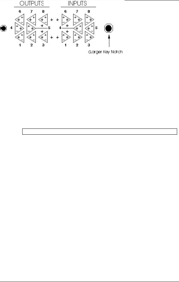
Balanced Tape I/O
The BALANCED TAPE I/O is a 56 pin ELCO connector designed to deliver eight channels of balanced +4 dBu tape inputs and outputs, such as that on the Alesis ADAT Digital Multi Track Recorder. There are three BALANCED TAPE I/O connectors provided which, when connected to three ADATs, provide the tape sends and returns of 24 digital tape tracks. The unbalanced and balanced outputs are available simultaneously. The wiring scheme for this connector is as follows:
Note: The larger of the two key notches is on the right. When connecting to an ADAT, the cable should be wired pin-to-pin (not flipping inputs and outputs).
To connect an ELCO cable to the X2:
1Place the male connector of the cable directly on any one of the ELCO-type connectors of the X2.
The cable will only fit on the connector one way. If you have trouble attaching the cable, rotate the cable’s end around 180° and try again.
2Push the cable into the connector slightly.
3Tighten the screw in the center of the connector while pushing in.
4After turning the screw a few times, push the connector itself in.
5Tighten the screw repeatedly until the cable is tightly connected to the X2.
®ELCO is a registered trademark of Elco Corporation - a Kyocera Group Company
X2 Reference Manual |
25 |
Connecting the X2
Stereo Returns and Groups
Each of the four Group modules contain two 1/4" GROUP OUT connectors (for a total of eight Group Outs), two TRS 1/4" GROUP INSERT connectors (for a total of eight Group Inserts), and four 1/4" RETURN connectors (for a total of eight Stereo Returns). Here are detailed descriptions of each.
Group Outputs
The GROUP Outputs are unbalanced 1/4" connectors which are available for connection to the inputs of a multitrack tape machine. Note, however, that in most applications it is more flexible to use the TAPE OUT jacks for this purpose, since they can receive either the Group Outputs or the direct output of each channel. In certain applications, such as video post-production, a pair of Group Outputs may be used to provide a different mix than the Main Outputs, such as a mix containing music and effects but minus the dialog.
Group Inserts
The GROUP Inserts are TRS 3-conductor 1/4" connectors which consist of an insert send (the tip of the TRS plug) and an insert return (the ring of a TRS plug). They are used to insert an outboard effects device (such as a compressor, EQ, or chorus) directly into the signal path of the corresponding Group. A Y-cable consisting of a stereo 1/4" plug on one end and two mono 1/4" plugs on the other end is required.
Group Insert Points
Send |
Tip |
Return |
Ring |
Ground |
Sleeve |
Tip |
|
Ring |
Sleeve |
Aux A & B Returns
The STEREO AUX RETURNS are made up of sixteen 1/4" jacks especially dedicated to the stereo signals returning from up to 8 outboard effects. However, these may also be used as additional inputs for stereo sound modules, samplers or synthesizers, if desired.
26 |
X2 Reference Manual |

Connecting the X2
Master Inputs and Outputs
The Master Module contains two balanced 1/4" MASTER OUT jacks, two TRS 1/4" MASTER INSERT jacks, two balanced 1/4" CONTROL ROOM output jacks, two 1/4" STUDIO jacks, and two pair of 1/4" jacks that serve as EXTERNAL 1 IN and EXTERNAL 2 IN. Additionally, a PHONES jack is found along the front end of the X2. Here are more detailed descriptions of each.
Master Outputs
The MASTER OUT consists of two balanced TRS 1/4" jacks which provide both the left and right signals, respectively. These may be connected to the inputs of a mixdown tape machine or a PA system amplifier.
Master Inserts
The MASTER INSERTS are two TRS 1/4" jacks, each of which consists of an insert send (the tip of the TRS plug) and an insert return (the ring of a TRS plug). They are used to insert an outboard effects device (such as a limiter, reverb or EQ) directly into the stereo signal path of only the left or right signal, depending on which it is connected to. A special Y-cable (stereo 1/4" plug to two mono 1/4" plugs) is required.
Control Room Outputs
The CONTROL ROOM Outputs consist of two balanced TRS 1/4" jacks which provide both the left and right signals, respectively. These may be connected to the inputs of an amplifier for control room monitor speakers. The signal level is controlled by the CONTROL ROOM knob.
Studio Outputs
The STUDIO Outputs consist of two unbalanced 1/4" jacks which provide both the left and right signals, respectively. These may be connected to the inputs of an amplifier for studio monitor speakers, or to a headphone amp. The signal level is controlled by the STUDIO knob.
External 1 & 2 Inputs
The EXT 1 IN and EXT 2 IN consist of two 1/4" jacks each for connection to the outputs of a mixdown tape machine. This allows you to playback your mix without repatching. The second input may be used for a CD player or VCR audio output.
Aux Sends
The AUX SENDS are eight unbalanced 1/4" jacks which feed the signals from Aux 1 through 8. Aux Sends 1 and 2 are Pre-Fader, and are ideal for feeding a headphone amp for musicians in the studio to monitor themselves and other tracks already recorded onto tape. However, depending on your studio hookup, you may find it more flexible to connect the headphone amp to the STUDIO OUT jacks, which may be switched to receive the Aux 1-2 signals or the Control Room mix. Aux 3 - 8 are Post-Fader, and are normally connected to the inputs of outboard effects devices,
X2 Reference Manual |
27 |

Connecting the X2
like reverbs and digital delays.
28 |
X2 Reference Manual |

Connecting the X2
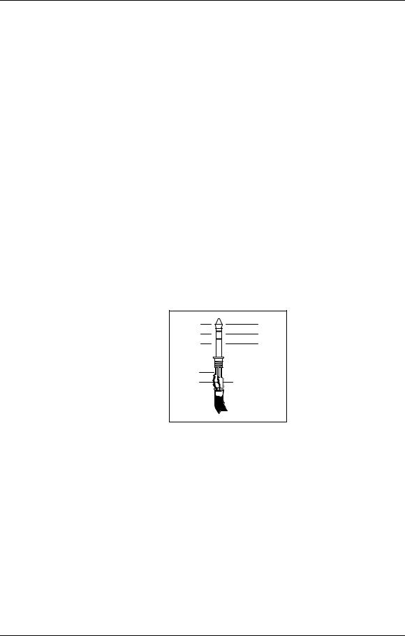
Headphones
The PHONES connector (found on the front end of the console, directly below the Master faders) is a stereo 1/4" jack which provides a substantial level to drive most headphones. The signal level is controlled by the PHONES knob. The wiring scheme is as follows.
Headphones
Left Signal |
Tip |
Right Signal |
Ring |
Ground |
Sleeve |
Tip |
|
Ring |
Sleeve |
ADAT Sync
The ADAT SYNC is a 9-pin, D connector which is designed to connect to an ADAT system. The X2 uses the proprietary timecode found on an ADAT formatted tape to synchronize its Dynamic Mute Automation system to tape. For more information, refer to Chapter 5.
To synchronize the X2 to an ADAT system:
1Connect one end of a male/male, D connector cable to the SYNC OUT connector of the last ADAT in your system.
2Connect the other end of this cable to the ADAT SYNC connector on the back of the X2.
MIDI
The MIDI IN, OUT and THRU are standard 5 pin DIN connectors, and are provided for interfacing the Dynamic Mute Automation system with a MIDI sequencer or other MIDI devices. The MIDI IN connector is for connecting to the MIDI Out of a MIDI device, while the MIDI OUT connector is for connecting to the MIDI In of the device. The X2’s MIDI THRU connector is provided for connecting other MIDI equipment that you wish to control from the MIDI device you have connected to the X2’s MIDI IN and MIDI OUT connectors.
For more information see Chapter 5.
X2 Reference Manual |
29 |
 Loading...