


ALESIS
Studio 32
Reference Manual

|
Contents |
CONTENTS |
|
Important Safety Instructions ................................................... |
5 |
Safety symbols used in this product......................................................................... |
5 |
Please follow these precautions when using this product:......................................... |
5 |
Introduction ................................................................................. |
7 |
How to use this manual .......................................................................................... |
7 |
For beginners.............................................................................................. |
7 |
For the experienced: a quick overview.................................................................... |
9 |
About the Studio 32................................................................................................ |
10 |
Basic Principles of Mixing & Multitrack Recording.................................................. |
11 |
The stages of multitrack recording .............................................................. |
12 |
The different mixes and what they’re needed for .................................................... |
14 |
Multitrack Mix .......................................................................................... |
14 |
Monitor (Control Room) Mix ....................................................................... |
16 |
Aux Sends and Returns: Effects ................................................................... |
18 |
Guided Tour................................................................................. |
19 |
Recorder Mix/Monitor Mix System.......................................................................... |
19 |
Starting at the source: input and TRIM ....................................................... |
19 |
The equalizer............................................................................................. |
20 |
Fader and assignment section...................................................................... |
20 |
Monitor 1/2 section..................................................................................... |
21 |
Aux Send/Return System ........................................................................................ |
22 |
Aux sends................................................................................................... |
22 |
Stereo Aux Returns ..................................................................................... |
22 |
Control Room System.............................................................................................. |
23 |
Control Room source.................................................................................... |
23 |
Solo/PFL ................................................................................................... |
23 |
Meters ....................................................................................................... |
24 |
Hooking It Up............................................................................... |
25 |
Unpacking and Inspection....................................................................................... |
25 |
Installing in a Rack................................................................................................ |
25 |
Power .................................................................................................................... |
26 |
Avoiding ground loop noise......................................................................... |
27 |
Channel Inputs and Outputs.................................................................................... |
28 |
Mic Inputs.................................................................................................. |
28 |
Line Inputs................................................................................................. |
28 |
Tape Inputs................................................................................................ |
29 |
Direct Outputs ........................................................................................... |
29 |
Insert......................................................................................................... |
30 |
Master Inputs and Outputs...................................................................................... |
31 |
Main Outputs............................................................................................. |
31 |
Main Inserts............................................................................................... |
31 |
Group Outputs............................................................................................ |
31 |
Control Room Outputs................................................................................. |
31 |
2 Track Inputs............................................................................................. |
31 |
Stereo Aux Returns ..................................................................................... |
32 |
Monitor and Auxiliary Outputs................................................................... |
32 |
Headphones .............................................................................................. |
32 |
Chart of Connections .............................................................................................. |
33 |
Studio 32 Reference Manual |
1 |

Contents |
|
Connecting to an Unbalanced -10 dBV Multitrack Recorder .......................... |
34 |
Connecting to a Professional +4 dBu Multitrack Recorder ............................. |
35 |
Connecting to a 2-Track Mixdown Deck........................................................ |
36 |
Connecting to a Control Room amplifier ...................................................... |
37 |
Connecting to a Headphone Amp ................................................................ |
37 |
Connecting to a Patchbay............................................................................ |
37 |
Effects and Signal Processing ................................................... |
39 |
Connecting Aux Sends and Returns to Outboard Effects ............................................. |
39 |
Should you use one or two inputs to effects?.................................................. |
40 |
Using Effects.......................................................................................................... |
41 |
Connecting Signal Processors to Insert Jacks.............................................................. |
44 |
Multitrack Recording Applications ........................................... |
46 |
Recording............................................................................................................... |
46 |
Setting Levels............................................................................................ |
46 |
How to Record a Single Source to One Track................................................. |
48 |
Recording Multiple Sources to One Track..................................................... |
49 |
Recording Multiple Sources to Two Tracks (Stereo) ...................................... |
50 |
Recording Tips ........................................................................................... |
51 |
About Metering .......................................................................................... |
51 |
Overdubbing .......................................................................................................... |
52 |
Using MONITOR 1/2 to Monitor the Multitrack.......................................... |
52 |
Using the Channel Faders to Monitor the Multitrack................................... |
53 |
Getting the Mix to the Headphones............................................................ |
55 |
Monitoring MIDI Virtual Tracks................................................................. |
56 |
Bouncing Tracks.......................................................................................... |
57 |
Playback/Mixdown................................................................................................ |
59 |
Getting the Mix to the 2-Track Deck ........................................................... |
59 |
Mixdown Basics ......................................................................................... |
59 |
Guidelines for a rough mix.......................................................................... |
60 |
Sound Reinforcement Applications .......................................... |
63 |
Creating a mono house mix...................................................................................... |
63 |
Subgrouping with the Group Faders ........................................................................ |
63 |
Stage Monitor Mix...................................................................................... |
64 |
Alternate uses for the Monitor 1/2 section: Stereo recording during a live concert...... |
65 |
Using Monitor 1/2 to feed a cassette deck..................................................... |
65 |
Using Monitor 1/2 as the PA mix during multitrack recording....................... |
66 |
Video Production and Post-Production..................................................................... |
67 |
Description of Controls ............................................................... |
69 |
Channel Input Controls........................................................................................... |
69 |
Trim .......................................................................................................... |
69 |
Fader Source switch ................................................................................... |
69 |
Equalizer section.................................................................................................... |
70 |
75 Hz switch.............................................................................................. |
70 |
EQ IN Switch ............................................................................................ |
70 |
HIGH and LOW......................................................................................... |
70 |
MID EQ controls: LEVEL, FREQ, and Q....................................................... |
70 |
Auxiliary Send Section........................................................................................... |
72 |
AUX 3(5) SOURCE Switch......................................................................... |
72 |
AUX 3(5) and AUX 4(6) Sends..................................................................... |
72 |
TO 5/6 Switch (Aux Assign Switch)............................................................ |
72 |
MONITOR 1/2 SOURCE switch ................................................................. |
72 |
Studio 32 Reference Manual |
2 |

|
Contents |
MONITOR 1/2 LEVEL, MONITOR 1/2 PAN............................................... |
73 |
Channel Output Section.......................................................................................... |
73 |
Channel PAN ............................................................................................ |
73 |
MUTE........................................................................................................ |
73 |
PEAK LED................................................................................................. |
73 |
-20 dB (Signal Present) LED........................................................................ |
73 |
SOLO ........................................................................................................ |
74 |
Group Assign Switches (1/2, 3/4) ................................................................ |
74 |
L/R Switch................................................................................................ |
74 |
Channel Fader........................................................................................... |
74 |
MASTER SECTION................................................................................................ |
75 |
Power and Phantom indicators.................................................................... |
75 |
Headphones Level and Source .................................................................... |
75 |
Phone jacks ................................................................................................ |
75 |
Stereo Aux Return Section....................................................................................... |
75 |
MON 1/2 ................................................................................................... |
75 |
LEVEL....................................................................................................... |
75 |
L/R Assign Switch ..................................................................................... |
75 |
GRP 1/2 Assign Switches (Stereo Aux Return A and B Only)......................... |
76 |
GRP 3/4 Assign Switches (Stereo Aux Return C and D Only)......................... |
76 |
SOLO IN PLACE Switch ........................................................................... |
76 |
Aux Master Controls............................................................................................... |
77 |
Auxiliary Masters...................................................................................... |
77 |
Monitor 1/2 Master..................................................................................... |
77 |
LINK TO L/R switch.................................................................................. |
77 |
Control Room/Solo Section ..................................................................................... |
78 |
Solo Master Level ...................................................................................... |
78 |
Solo SIP/PFL switch .................................................................................. |
78 |
Control Room Level and Source ................................................................... |
78 |
MONO ...................................................................................................... |
79 |
Master L/R Fader....................................................................................... |
79 |
Meters ....................................................................................................... |
79 |
Group Master Controls............................................................................................ |
80 |
TO L/R switches ........................................................................................ |
80 |
MONO switch ........................................................................................... |
80 |
Group 1—4 Master...................................................................................... |
80 |
L/R Master Fader....................................................................................... |
80 |
Back panel............................................................................................................. |
81 |
POWER switch.......................................................................................... |
81 |
Power cable................................................................................................ |
81 |
PHANTOM Switch.................................................................................... |
81 |
Control Room Out....................................................................................... |
81 |
2 Track Tape In........................................................................................... |
81 |
Main Outs.................................................................................................. |
82 |
Main Inserts............................................................................................... |
82 |
Group Outputs............................................................................................ |
82 |
Stereo Aux Return Input Jacks...................................................................... |
82 |
Auxiliary Outputs (including Mon 1/2)........................................................ |
82 |
Channel Input/Output Jacks (16)............................................................................. |
82 |
Direct Out.................................................................................................. |
82 |
Tape In ...................................................................................................... |
83 |
Insert jack .................................................................................................. |
83 |
Line In jack................................................................................................. |
83 |
Mic In jack.................................................................................................. |
83 |
Studio 32 Reference Manual |
3 |

|
Contents |
Troubleshooting .......................................................................... |
85 |
Troubleshooting Index ............................................................................................ |
85 |
Maintenance/Service ............................................................................................. |
86 |
Specifications............................................................................... |
89 |
Frequency Response ................................................................................................ |
89 |
Connectors.............................................................................................................. |
89 |
Levels.................................................................................................................... |
89 |
Impedance ............................................................................................................. |
90 |
Noise performance (typical)................................................................................... |
90 |
Distortion (THD+N).............................................................................................. |
90 |
Power .................................................................................................................... |
90 |
Mounting dimensions .............................................................................................. |
90 |
Dimensional Drawings:.......................................................................................... |
92 |
Gain Diagram ............................................................................... |
93 |
Block Diagram ............................................................................. |
94 |
Index............................................................................................. |
96 |
Studio 32 Reference Manual |
4 |

Introduction
CHAPTER 1
INTRODUCTION
How to use this manual
You’ve taken the leap and purchased an Alesis Studio 32 Recording Console with Inline Monitor. Congratulations. At Alesis, we design equipment that’s used by everyone from first-time users to engineers with decades of experience. In either case, the Studio 32 packs a lot of power into a small package, and we wrote this manual so that no matter what your background is, you can get the most out of it.
For beginners
The first two chapters are designed to give you a background in console operation. If you read them carefully, the rest of the manual will be easier to understand, and you’ll be happier with your results. Mixers really aren’t as difficult as they seem to be, but there’s a lot of things going on at one time.
Chapter 1: Introduction describes the capabilities of the Studio 32 and explains the basic principles of mixing and recording.
Chapter 2: Guided Tour provides a brief tour of the Studio 32, and shows you how the basic principles of all console operation apply to the particular features of the Studio 32.
Chapter 3: Connections details installation and power hookups, rear panel connections (inputs, outputs, and cables), and typical hook-up procedures.
Chapter 4: Effects and Signal Processing contains information on how to connect external effects and how to use them properly. If you don’t read any other chapter, read this one–effects send and return is one of the most misunderstood aspects of mixing consoles.
Chapter 5: Recording Applications covers the various uses for the Studio 32 in multitrack recording, with step-by-step instructions on setting up and mixing techniques.
Chapter 6: Sound Reinforcement Applications covers the Studio 32’s features when it’s connected to a PA system; but this chapter will also be useful for those doing live recording.
Chapter 7: Description of Controls is a “dictionary” of each control for fast reference.
Chapter 8: Troubleshooting. A guide to trouble-free operation, maintenance and service information.
We have also included a block diagram, Gain Structure Chart and an Index.
Studio 32 Reference Manual |
7 |

Introduction
We appreciate your feedback. If you have any suggestions on how to improve this manual, please write to us at:
Technical Communications Dept.
Alesis Corp.
3630 Holdrege
Los Angeles, CA 90016
or via email at: alecorp@alesis1.usa.com
Conventions
The buttons, knobs, and rear panel connectors are referred to in this manual just as their names appear on the Studio 32, using all capital letters (Example: TRIM control, PAN knob, MIC IN jack, etc.).
When something important appears in the manual, an icon (like the one on the left)
will appear in the left margin. This symbol indicates that this information is vital when operating the Studio 32.
Studio 32 Reference Manual |
8 |

Introduction
For the experienced: a quick overview
If you're already familiar with mixing consoles, here are some important points you need to know about the Alesis Studio 32 Recording Console. The Studio 32 follows commonly-accepted traditions for signal levels and routing.
Channel Input Jacks: All inputs and outputs are balanced except the INSERT jacks and Stereo Aux Returns. All other 1/4” jacks are TRS 3-conductor types and may be used with +4 dBu balanced or -10 dBV unbalanced systems. The XLR and LINE IN jacks do not have a switch between them, and use the same TRIM control, so you can only use one of them at a time. The TAPE IN jacks are entirely independent, have no TRIM control, and can handle input levels up to +25 dBu.
PEAK indicator headroom: The PEAK LED in each channel will light 5 to 6 dB before the onset of actual channel clipping. The same is true for the PK segment of the main meter (which corresponds to +18 dB over reference). PEAK is monitored both preand post-EQ.
Monitor LINK TO L/R: Unlike most other monitors, the Studio 32's monitor busses are independent from the L/R mix, unless you LINK them to the L/R using the switch. Think of them as an AUX 1/2 send with independent input source selection from the channel source, which can be submixed into the L/R if desired.
EQ: The 75 Hz high-pass filter switch is independent of the EQ and may be used even if the EQ IN switch is out. The midrange controls are fully parametric. The EQ section affects the channel path only, not the MONITOR 1/2 section.
AUX: There are four post-fader Aux send busses, with two knobs from each channel. Both knobs in a channel are assigned to a pair of auxes by the same AUX ASSIGN switch: 3/4, or 5/6. The upper control can send from the Monitor or the Channel; the lower control is always from the channel.
SOLO: Whether the SOLO keys function as SIP (stereo solo-in-place, also known as After-Fader-Listen or AFL) or PFL (Pre-Fader-Listen) is selected by a master solo status switch next to the Control Room section. The Stereo Aux Returns can only be soloed in SIP mode.
FADERS and gain structure: The Group and L/R master faders are designed with a nominal "0" position at the top of their travel, not the 3/4 position. The channel faders have 10 dB of gain from the nominal position to the top of fader travel. Most other pots are marked with a nominal position (usually "2 o'clock"). The L/R, Group, and Direct outputs add an extra 6 dB of gain when used in balanced mode.
Chapter 5 “Description of Controls” gives a knob-by-knob definition of each feature of the Studio 32, so if you know what the “Q” controls do, but you need more information on “LINK TO L/R”, this is where you can look it up. In any case, please remember after you get started that this manual contains information that will help you get the highest level of performance from your Studio 32. Even an expert may pick up some creative alternative techniques that aren't obvious at first glance.
To find what you need quickly, refer to the index at the back of the manual, or the Table of Contents.
Studio 32 Reference Manual |
9 |

Introduction
About the Studio 32
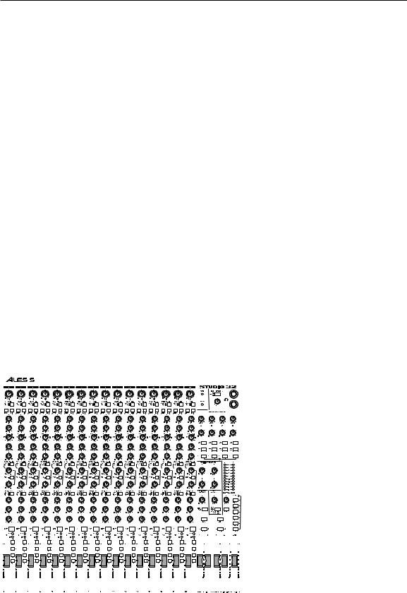
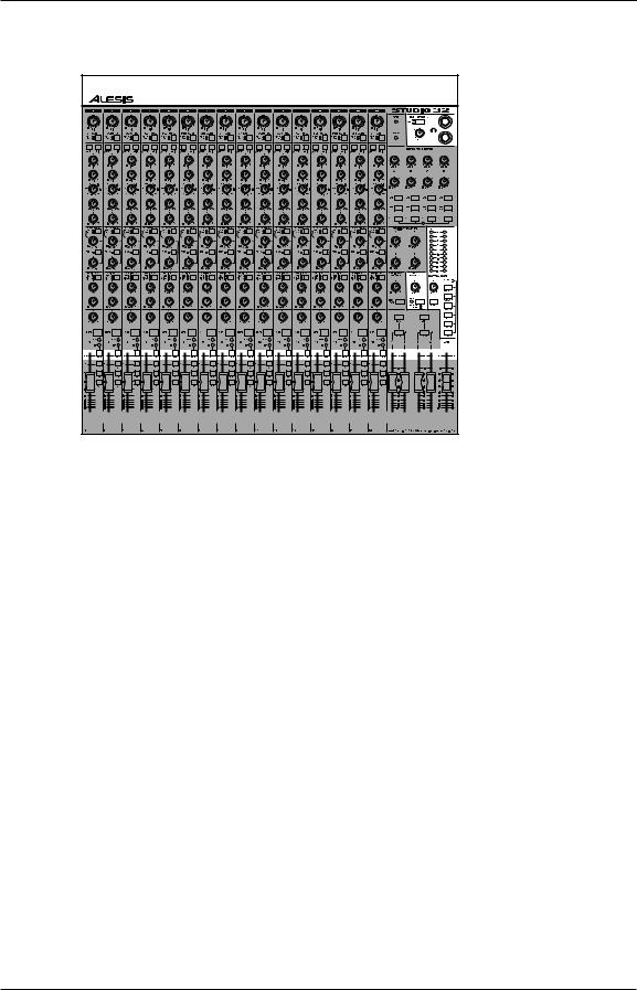
The Studio 32 is an extremely flexible, 16-channel, 4-group plus L/R output, in-line monitor professional audio mixing console. The MONITOR 1/2 path of each channel has its own volume, pan, and access to the channel’s upper Aux send knob, so you can mix or monitor the tape input while the main channel path mixes a mic or line input. Each monitor control has its own source switch, so it may be used as a conventional pre-fader auxiliary send as well as a tape monitor section. The MONITOR 1/2 mix may be linked to the main stereo output, but also features its own 1/4” output jacks. This flexible design allows full mix control of 32 sources, plus 8 aux returns, for a total of 40 sources at mixdown. For this reason, the Studio 32 is perfectly suited for professional project studios with a large number of MIDI sequencer-controlled sources that are synchronized with 16 tracks of ADAT. It also makes an excellent console for live sound reinforcement use.
Each channel features a high-quality 3-band equalizer with a fully parametric (not just sweep) midrange band. The midrange Q (bandwidth) can be set as narrow as 1/6th of an octave, or as wide as several octaves, for boosting or cutting any frequency range desired. An EQ IN/OUT switch permits the entire EQ circuit to be bypassed when desired, maintaining the minimum signal path. A switchable 75 Hz high-pass filter removes low frequency rumble and noise.
The Studio 32 uses fully balanced +4 dBu inputs on 1/4" jacks for all LINE IN and TAPE IN connections. The Studio 32 may also be used with unbalanced -10 dBV level equipment. Each channel has its own balanced Direct Out, so that simultaneous 16-track recording is possible.
All channels feature a high-quality, low-noise balanced microphone preamp with globally switchable 48-volt phantom power for condenser microphones. Each input channel features a green “-20 dB signal present” LED and a red PEAK LED to warn of input signals that are too high for the present trim or EQ setting. The MUTE and SOLO switches use these same LEDs to indicate when a channel is muted or soloed.
Effects mixes are handled by four post-fader Aux send busses, with two controls in each channel that are assignable to either Aux 3-4 or Aux 5-6. The upper control, labeled Aux 3(5), features its own input source select switch that allows it to provide an effects send from either the channel fader or monitor level control. The lower control, Aux 4(6), is a post-fader send that’s always sourced from the main channel fader. Four Stereo Aux Returns (labeled A, B, C, and D) are provided, each with its own assignment switches and MON 1/2 send control. Returns may be routed to the stereo mix, the groups, soloed to the control room, and added to the monitor mix, so that effects may be added to the final mix, printed to multitrack, monitored on headphones, or any combination desired. The Studio 32 provides insert points on each channel and the stereo main outputs, for use with compressors and graphic equalizers.
Control room monitoring is made simpler by stereo-in-place Solo on each main channel, which is globally switchable to PFL (Pre-fader listen). Each Auxiliary mix and Group may be previewed in the control room while leaving the rest of the signal path undisturbed. Two built-in headphone jacks with a separate source select switch allow you to hear either the control room source, or the monitor mix.
Studio 32 Reference Manual |
10 |
Introduction
Basic Principles of Mixing & Multitrack
Recording
Source select, level control, and destination assignment
When it’s being used in a recording studio, the Studio 32’s job is to control the volume, tone, pan and effects for many different inputs such as microphones, electronic instruments, and tape machines. You could think of this as the “where from” (source select) and “how much” (level control) function of the console. Then, it must route these signals to a monitor system and tape recorder so they can be heard and recorded: this is the “where to” (assignment) function of the console.
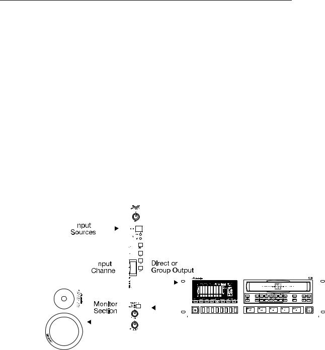
The two-way signal flow of multitrack recording
Using a console for recording is very different from a live PA application, where signal basically flows in one direction from the microphones to the speakers. During multitrack recording, signal flows two ways: from the input sources through the mixer to the recorder, and simultaneously back from the recorder through the monitor section to speakers or headphones so the musicians can play along with previously-recorded tracks. This two-way flow is what makes a true recording console more versatile than a PA-only console.
|
|
|
|
|
|
|
|
|
|
|
|
|
|
|
|
|
|
|
|
|
|
|
|
|
|
|
|
|
|
|
|
|
|
|
|
|
|
|
|
|
|
|
|
|
|
|
|
|
|
|
|
|
|
|
|
|
|
|
|
|
|
|
|
|
|
|
|
|
|
|
|
|
|
|
|
|
|
|
|
|
|
|
|
|
|
|
|
|
|
|
|
|
|
|
|
|
|
|
|
|
|
|
|
|
|
|
|
|
|
|
|
|
|
|
|
|
|
|
|
|
|
|
|
|
|
|
|
|
|
|
|
|
|
|
|
|
|
|
|
|
|
|
|
|
|
|
|
|
|
|
|
|
|
|
|
|
|
|
|
|
|
|
|
|
|
|
|
|
|
|
|
|
|
|
|
|
|
|
|
|
|
|
|
|
|
|
|
|
|
|
|
|
|
|
|
|
|
|
|
|
|
|
|
|
|
|
|
|
|
|
|
|
|
|
|
|
|
|
|
|
|
|
|
|
|
|
|
|
|
|
|
|
|
|
|
|
|
|
|
|
|
|
|
|
|
|
|
|
|
|
|
|
|
|
|
|
|
|
|
|
|
|
|
|
|
|
|
|
|
|
|
|
|
|
|
|
|
|
|
|
|
|
|
|
|
|
|
|
|
|
|
|
|
|
|
|
|
|
|
|
|
|
|
|
|
|
|
|
|
|
|
|
|
|
|
|
|
|
|
|
|
|
|
|
|
|
|
|
|
|
|
|
|
|
|
|
|
|
|
|
|
|
|
|
|
|
|
|
|
|
|
|
|
|
|
|
|
|
|
|
|
|
|
|
|
|
|
|
|
|
|
|
|
|
|
|
|
|
|
|
|
|
|
|
|
|
|
|
|
|
|
|
|
|
|
|
|
|
|
|
|
|
|
|
|
|
|
|
|
|
|
|
|
|
|
|
|
|
|
|
|
|
|
|
|
|
|
|
|
|
|
|
|
|
|
|
|
|
|
|
|
|
|
|
|
|
|
|
|
|
|
|
|
|
|
|
|
|
|
|
|
|
|
|
|
|
|
|
|
|
|
|
|
|
|
|
|
|
|
|
|
|
|
|
|
|
|
|
|
|
|
|
|
|
|
|
|
|
|
|
|
|
|
|
|
|
|
|
|
|
|
|
|
|
|
|
|
|
|
|
|
|
|
|
|
|
|
|
|
|
|
|
|
|
|
|
|
|
|
|
|
|
|
|
|
|
|
|
|
|
|
|
|
|
|
|
|
|
|
|
|
|
|
|
|
|
|
|
|
|
|
|
|
|
|
|
|
|
|
|
|
|
|
|
|
|
|
|
|
|
|
|
|
|
|
|
|
|
|
|
|
|
|
|
|
|
|
|
|
|
|
|
|
|
|
|
|
|
|
|
|
|
|
|
|
|
|
|
|
|
|
|
|
|
|
|
|
|
|
|
|
|
|
|
|
|
|
|
|
|
|
|
|
|
|
|
|
|
|
|
|
|
|
|
|
|
|
|
|
|
|
|
|
|
|
|
|
|
|
|
|
|
|
|
|
|
|
|
|
|
|
|
|
|
|
|
|
|
|
|
|
|
|
|
|
|
|
|
|
|
|
|
|
|
|
|
|
|
|
|
|
|
|
|
|
|
|
|
|
|
|
|
|
|
|
|
|
|
|
|
|
|
|
|
|
|
|
|
|
|
|
|
|
|
|
|
|
|
|
|
|
|
|
|
|
|
|
|
|
|
|
|
|
|
|
|
|
|
|
|
|
|
|
|
|
|
|
|
|
|
|
|
|
|
|
|
|
|
|
|
|
|
|
|
|
|
|
|
|
|
|
|
|
|
|
|
|
|
|
|
|
|
|
|
|
|
|
|
|
|
|
|
|
|
|
|
|
|
|
|
|
|
|
|
|
|
|
|
|
|
Studio 32 Reference Manual |
11 |
|
|
|
|
|||||||||||||||||||||||||||||||
Introduction
The stages of multitrack recording
Most multitrack recording is a three-stage process. Instead of recording an entire musical group in a single take of a live performance, recordings are usually made one instrument at a time and built up in layers. Recording one instrument at a time makes it easier to fix mistakes of an incorrectly played part. The signal flow may seem complex, but it’s easy to understand the functions of the Studio 32 once you understand the basic signal flows of each stage: tracking, overdubbing, and mixdown.
Recording/Tracking
When recording the first tracks, which define the tempo and basic structure of the song, signal flows in one direction: from the sources through the mixer to the recorder. Monitoring the playback from the multitrack isn’t necessary, although you may need to provide a headphone mix, which can come either from the sources or through the multitrack (because at this stage, they’re the same thing).
Monitoring/Overdubbing
In order to properly record a performance, the engineer, the producer, and all of the players must be able to hear what’s going on. Traditionally, the engineer listens to speakers in the control room (where the mixer is). This is called monitoring. In the studio, the musicians listen to a cue mix in headphones while overdubbing.
Adjustments to monitor or cue mixes should not affect the mix going to the recorder, so that recording levels remain set at the optimum, regardless of what the monitor mix needs to be.
During overdubbing, it’s easy to get confused, since there may be three or more separate mixes happening at the same time. As long as you keep them separate in your mind, and keep track of what’s going where, the Studio 32 will let you get almost any sound mix you want.
Mixdown
In the final stage of multitrack recording, you take all the parts that were separated so they could be perfected, and recombine them so an audience can hear them. Mixdown is the “reverse flow”: now the multitrack is the source (sometimes supplemented by MIDI-controlled “virtual tracks”) and a 2-track stereo recorder is the destination. During this stage, the tracks are blended together, tonally enhanced with EQ and effects, positioned in the stereo field with the PAN controls, and finally recorded onto a mixdown tape deck (such as a DAT machine, 2- Track reel-to-reel or cassette recorder, or 2 tracks of an ADAT). During mixdown, the engineer must hear the exact same mix the recorder is receiving. For this purpose, the Control Room section of the Studio 32 provides an external 2 TRACK input for listening to the output of the mixdown tape deck.
Studio 32 Reference Manual |
12 |

Introduction
Studio 32 Reference Manual |
13 |

Introduction
The different mixes and what they’re needed for
Now that you understand the different sources and different destinations used during the three stages of the multitrack recording process, let’s look at each one individually, without the other components getting in the way. Please note that these illustrations show the controls in the order they are electronically, and omit controls that don’t apply to the mix being explained. Here are the mixes that you will control during a typical multitrack recording session:
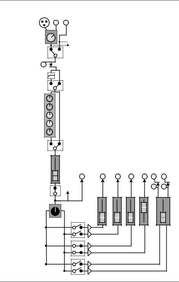
Multitrack Mix
This mix goes from the sources (microphones or line inputs) to the tracks of the multitrack recorder. It is controlled by the Channel Faders and sent via the four Group Master Faders to the Group Output jacks. (If you need to record more than four tracks at once, some signals will go to the multitrack directly from Channel Faders via the Direct Out jacks.) In the multitrack mix, the goal is to set the controls so that each track is recorded as loud as it can be without distorting the recorder.
For example, a microphone is plugged into channel 1, and its level is set by the TRIM control. The FADER SOURCE switch is left in the UP position (MIC/LN). After passing through the INSERT jack on the rear panel, signal may then pass through the 75 Hz filter (if its switch is down) and the EQ (if the EQ IN switch is down) on its way to the Channel Fader and MUTE switch. At this point, signal is available to the DIRECT OUT jack (where it may be connected to the multitrack); in any case it then goes on to the channel PAN and the 1/2, 3/4, and L/R assignment switches. The channel PAN affects what group (odd, even or both) the mic will be sent to. The mic is mixed with any other channel sources feeding the same group, via the Group Master faders to the selected track (in the illustration, Group and track 4).
Please note a key concept: you can go from any channel input to any of the group or main outputs. Inputs and tracks are independent of each other. You can plug a mic into channel 1, and record it on track 4 without repatching.
Studio 32 Reference Manual |
14 |
Introduction
TRIM
FADER SOURCE
INSERT jack
75 HZ
HIGH
MID
FREQ
Q
LOW
EQ IN
MIC |
LINE TAPE |
Multitrack Recorder Mix |
IN |
IN IN |
(Groups and L/R) |
|
 (to MON 1/2 SOURCE)

 (Post-EQ to MON 1/2 SOURCE when
MIC/LINE is selected at both)
|
|
|
MAIN L/R |
|
DIRECT |
|
OUTS & |
FADER |
OUT |
GROUP OUTPUTS |
INSERTS |
|
(to AUX |
|
|
|
|
MUTE |
sends) |
|
|
|
|
|
|
|
|
|
|
|
1 |
2 |
3 |
4 |
L/R |
PAN |
|
|
|
|
|
GRP 1/2 |
|
|
|
|
|
(combined with signals from other channels)
GRP 3/4
L/R
Studio 32 Reference Manual |
15 |

Introduction
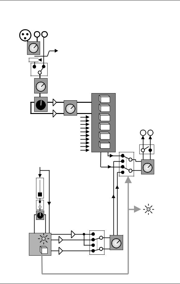
Monitor (Control Room) Mix
This mix is what the engineer and/or performer hears in headphones or the control room speakers. During overdubbing, this mix is typically controlled by the Studio 32’s MONITOR 1/2 section, and sometimes by the L/R mix. In the monitor mix, the goal is to set the controls so the performer gets whatever mix they need so they can perform their overdubs as well as possible. In the engineer’s mix, the goal is to make sure that he or she can hear any problems with the tracks being recorded, so they can be fixed before making more overdubs. In either case, the Studio 32 allows you to adjust the monitor and control room mix (change levels, pan position, or solo individual channels) without disturbing the signals being recorded to the multitrack.
In the illustration, the microphone we recorded on track 4 comes back on TAPE IN #4. The MONITOR 1/2 source switch is set to the TAPE (up) position. The LEVEL pot (with the purple knob), and the MONITOR PAN determine the mix going to the MONITOR 1/2 MASTER. At this point, the CONTROL ROOM SOURCE switch is set to MON 1/2, so the engineer can adjust the monitor mix, and the HEADPHONES SOURCE switch is set to MON 1/2 as well, so that if the engineer hits any SOLO buttons, only the control room mix will be affected, not the headphone mix.
Monitor PAN: Note that the Monitor PAN controls (the black knobs above the purple knobs) will not affect what track a signal is recorded on. They only affect the position in the control room speakers or headphones. On the other hand, the lower row of PAN controls for the channel faders will pan the signal from the microphone between two tracks of tape (if you’re recording using the Groups instead of the Direct Outs).
Sometimes you may need another mix for the musicians’ headphones, since some musicians may need certain instruments louder or softer in the mix in order to hear their cues. In the Studio 32, a complicated cue mix will usually come from MONITOR 1/2, and less complicated ones may come from the post-fader AUX sends (if it’s OK for the Aux mix to change if the engineer makes adjustments to the channel fader). Don’t forget that MONITOR 1/2, instead of being used as one stereo mix, may be used as two mono mixes, with careful setting of the MONITOR PAN controls.
Post-EQ, Pre-Fader: The EQ, 75 HZ filter, and INSERT jack do not affect the MONITOR 1/2 mix unless both the FADER SOURCE and MONITOR SOURCE switches have selected MIC/LINE as the source. This feature allows you to hear what the engineer is doing to the EQ, or to an effect device in the INSERT jack, when you’re using the MON 1/2 mix for headphones or a stage monitor mix. But the EQ and INSERT never affect the TAPE side of the MONITOR SOURCE switch, or if the MIC signal is going through MON 1/2 while TAPE is going through the CHANNEL FADER. (For clarity, the drawing on the next page doesn’t show this detail; see the Block Diagram on page Error! Bookmark not defined. for the complete signal flow.)
Studio 32 Reference Manual |
16 |
Introduction
Monitor/Control Room/Solo System
MIC LINE TAPE
IN IN IN
TRIM
MONITOR 1/2 SOURCE
MON
LEVEL
MON PAN
(Channel details on previous page)
Channel
fader
Channel
PAN
SOLO

 (to channel FADER
SOURCE switch)
 (MIC/LN source is post-EQ (EQ)
 when both SOURCE
switches are set to MIC/LN)
CONTROL
ROOM
SELECT MONITOR SWITCHES
1/2 MASTER
|
(from AUX, |
|
CONTROL |
|
GROUP, |
|
|
|
L/R masters |
|
ROOM |
|
and |
(Master |
|
|
2 TRK inputs) |
OUTPUTS |
|
|
|
solo |
|
|
|
|
|
|
|
takeover |
MONO |
|
|
relay) |
|
|
|
|
|
|
|
|
CONTROL |
|
|
|
ROOM |
|
|
|
LEVEL |
|
|
Any SOLO |
|
|
|
on console |
|
|
|
controls this |
|
|
|
relay |
|
|
|
electronically |
|
|
|
|
MASTER |
|
|
|
SOLO |
|
(PFLfeed) |
|
LED |
(SIP) |
|
|
|
-20 |
|
|
|
|
SIP/PFL |
SOLO |
|
SWITCH MASTER
Studio 32 Reference Manual |
17 |
Introduction
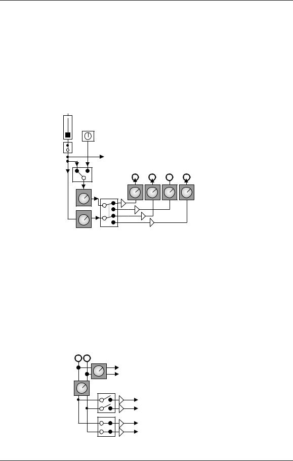
Aux Sends and Returns: Effects
The last important mix is usually used for adding effects (such as reverb, delay, chorus, etc.) to the mix. This may be part of the tracking and overdubbing stage, and is almost always part of the mixdown stage. The rows of blue knobs running across the center of the Studio 32 may be thought of as secondary submixers, with a little less independence from the other mixes, because they follow them in the signal path. This is the “send” side of the “effects send/receive” process. The upper row of AUX controls is capable of sending from either the MONITOR 1/2 mix (the row of purple knobs) or from the channel faders.
Aux Sends (16)
MONITOR
CHANNEL LEVEL
FADER

 (to monitor pan)
MUTE |
(to channel pan and assign) |
|
|
|
|
|
|
|
|
AUX 3(5) |
AUXILIARY OUTPUTS |
|
||
|
|
|
|
|
SOURCE |
3 |
4 |
5 |
6 |
|
||||
|
|
|
|
AUXILIARY |
AUX 3(5) |
TO 5/6 |
|
|
MASTERS |
AUX 4(6) |
|
|
|
|
Once you’ve made an effect, it’s no use unless you hear it, so the STEREO AUX RETURNS are four “miniature stereo channels” designed for effect returns. You may want to record effects to the multitrack, so they have GRP ASSIGN switches. The musicians may want some reverb in their headphones to help them stay on pitch, so it has a row of four MON 1/2 controls. The engineer may need to hear the output of a single effect device to change the delay time, so there are SOLO switches. And, of course, you want effects on the final mix, so they all have L/R ASSIGN switches.
Except for the limitations of not having a mic preamp, EQ, post-fader Aux Sends, or mute, the Aux Returns are just like channels--they don’t have to be used for effects. Consider them as an extra eight input channels especially for stereo line instruments such as synthesizers that already have their own internal effects.
Stereo Aux Returns (4)
STEREO AUX
RETURNS L, R
MON
(to Monitor 1/2 Master)
1/2
RETURN
LEVEL
GRP 1/2
(to GRP masters)
(or 3/4)
L/R |
(to L/R master) |
|
Studio 32 Reference Manual |
18 |

Guided Tour
CHAPTER 2:
GUIDED TOUR
Recorder Mix/Monitor Mix System
The Studio 32 is designed to accommodate the two-way signal flow required in a recording console. This is where signals are mixed, EQ’d and routed to the Aux sends, Groups and Left and Right Master outs. Each channel provides a Mic and Line Input plus a Tape In connector, where signals return from the multitrack recorder. Any input may be routed to either the main or monitor section of the channel, or even to both at once. This allows you to mix an input and monitor a tape signal simultaneously. Counting the Stereo Aux Returns, the Studio 32 has a total of 40 inputs to the main mix. These can all be mixed down to a master tape deck via the L/R Main outs.
Starting at the source: input and TRIM
Let’s trace the signal flow from beginning to end. Note that the controls from top to bottom of each channel are not placed in the same order as they appear in the signal flow. To see the paths of the signal flow, refer to the block diagram on page
Error! Bookmark not defined..
Each input module has three possible sources (line, mic and tape in) and two paths (the main channel and the monitor). First, the signal arrives at either the line or mic input of a channel; you should not plug into both at once. If using the mic input with a condenser microphone, the rear-panel PHANTOM switch will be turned on to provide phantom power (after the mics have all been plugged in). Next we come to the gray TRIM knob, which is used to set the initial level of the signal. It is
Studio 32 Reference Manual |
19 |

Guided Tour
important to set this level properly, since high levels could lead to distortion and levels set too low will cause noise (see Setting Levels).
Channel and Monitor source select switches: Each channel has its own FADER SOURCE SELECT switch, under the TRIM control, and MONITOR 1/2 SOURCE SELECT switch above the MONITOR 1/2 PAN control. These two switches are completely independent.
•If both switches are up, the TAPE INPUTS can be heard through the MONITOR 1/2 controls, while the MIC/LINE input appears at the main channel controls. This is the position normally used for tracking and overdubbing.
•If both switches are down, the tape returns are on the main channel while the MIC/LINE input appears at the monitor controls. This is the position normally used for mixdown (with the main channel assigned to L/R) or for bouncing tracks (with the main channel assigned to the appropriate Group or Groups).
•If the FADER SOURCE switch is up and the MONITOR SOURCE switch is down, MIC/LN is chosen for both. This is the position that would be used if MON 1/2 is going to be used for a pre-fader stage monitoring mix.
The equalizer
EQ section: The EQ section affects only the signal on the Channel fader, not the signal of the monitor section. An EQ IN switch allows you to hear the signal “flat” with no EQ at the touch of a button. Once the fader source has been chosen, and the EQ IN switch is down, signal will flow through the green knobs in the EQ section.
The EQ has three bands: the Hi & Lo EQ, and the fully-parametric Mid EQ. The Hi & Lo EQ are shelving-type EQs, with 12 kHz and 80 Hz shelving points and an adjustable boost or cut of ±15 dB. These act much like the bass and treble knobs found on most audio equipment: the “12 o’clock” position has no effect, and you turn to the right to get more of the frequencies and to the left to cut them.
The Mid EQ has three knobs: one to set the amount of boost or cut, one to select the frequency you want to control (adjustable from 150 Hz to 15 kHz), and a “Q” or bandwidth control. The Q control adjusts how wide an area around the selected frequency should be cut or boosted, allowing you to be extremely specific about how you tailor your sound.
To avoid low-end rumble and noise, turn on the 75 Hz high-pass filter, which removes frequencies below 75 Hz at a rate of 18 dB per octave. The 75 HZ switch has this effect even if the EQ IN switch is off.
Fader and assignment section
Channel controls: Finally, at the bottom of each channel we find the channel’s fader, PAN knob, SOLO and MUTE buttons, PEAK and -20 LEDs, and a set of buttons that let you determine the channel routing, i.e., where it’ll go to. The assignment switches can route the channel’s signal to any of the four Groups and to the L/R Master.
Studio 32 Reference Manual |
20 |
Guided Tour
Group mix: Once signals are routed to the Group section, you can use the GROUP FADERS to determine the total volume of all channels assigned there. In the studio, the Group output usually is connected to the inputs of a multitrack recorder, such as the Alesis ADAT. But in live performance applications, the Group Out jacks may be used to feed other amplifiers, broadcast feeds or even other mixers. Some engineers even use the Groups for extra effect sends.
Subgrouping: During mixdown or in PA applications, the Groups may be “subgrouped” or assigned to the L/R Main mix, using the TO L/R buttons above the GROUP FADERS. so that the Group Master faders can be used to adjust the volume of several different inputs at once, such as multiple channels of drums or vocals.
L/R master: Every input may be routed to the main left and right outputs, either directly or via a Group Master or the Monitor Link to L/R.
Monitor 1/2 section
In multitrack recording, once signal goes from the Group Outputs to the recorder, it comes back to the tape inputs. The TAPE IN jack has no trim control of its own; it is designed to handle the balanced or unbalanced line levels that all multitrack recorders generate. Each channel features an in-line monitor which selects either the tape return or the mic/line input source for the MONITOR 1/2 mix. The MONITOR 1/2 mix has its own MASTER LEVEL control and may be heard in several different ways:
•From its own output jacks connected to an external headphone amplifier
•the HEADPHONE jacks of the Studio 32, with the SOURCE switch down
•in the Control Room mix, with the MON 1/2 switch down
•in the L/R mix, if the LINK TO L/R switch is down
|
|
|
|
|
|
|
|
|
|
|
|
|
|
|
|
|
|
|
|
|
|
|
|
|
|
|
|
|
|
|
|
|
|
|
|
|
|
|
|
|
|
|
|
|
|
|
|
|
|
|
|
|
|
|
|
|
|
|
|
|
|
|
|
|
|
|
|
|
|
|
|
|
|
|
|
|
|
|
|
|
|
|
|
|
|
|
|
|
|
|
|
|
|
|
|
|
|
|
|
|
|
|
|
|
|
|
|
|
|
|
|
|
|
|
|
|
|
|
|
|
|
|
|
|
|
|
|
|
|
|
|
|
|
|
|
|
|
|
|
|
|
|
|
|
|
|
|
|
|
|
|
|
|
|
|
|
|
|
|
|
|
|
|
|
|
|
|
|
|
|
|
|
|
|
|
|
|
|
|
|
|
|
|
|
|
|
|
|
|
|
|
|
|
|
|
|
|
|
|
|
|
|
|
|
|
|
|
|
|
|
|
|
|
|
|
|
|
|
|
|
|
|
|
|
|
|
|
|
|
|
|
|
|
|
|
|
|
|
|
|
|
|
|
|
|
|
|
|
|
|
|
|
|
|
|
|
|
|
|
|
|
|
|
|
|
|
|
|
|
|
|
|
|
|
|
|
|
|
|
|
|
|
|
|
|
|
|
|
|
|
|
|
|
|
|
|
|
|
|
|
|
|
|
|
|
|
|
|
|
|
|
|
|
|
|
|
|
|
|
|
|
|
|
|
|
|
|
|
|
|
|
|
|
|
|
|
|
|
|
|
|
|
|
|
|
|
|
|
|
|
|
|
|
|
|
|
|
|
|
|
|
|
|
|
|
|
|
|
|
|
|
|
|
|
|
|
|
|
|
|
|
|
|
|
|
|
|
|
|
|
|
|
|
|
|
|
|
|
|
|
|
|
|
|
|
|
|
|
|
|
|
|
|
|
|
|
|
|
|
|
|
|
|
|
|
|
|
|
|
|
|
|
|
|
|
|
|
|
|
|
|
|
|
|
|
|
|
|
|
|
|
|
|
|
|
|
|
|
|
|
|
|
|
|
|
|
|
|
|
|
|
|
|
|
|
|
|
|
|
|
|
|
|
|
|
|
|
|
|
|
|
|
|
|
|
|
|
|
|
|
|
|
|
|
|
|
|
|
|
|
|
|
|
|
|
|
|
|
|
|
|
|
|
|
|
|
|
|
|
|
|
|
|
|
|
|
|
|
|
|
|
|
|
|
|
|
|
|
|
|
|
|
|
|
|
|
|
|
|
|
|
|
|
|
|
|
|
|
|
|
|
|
|
|
|
|
|
|
|
|
|
|
|
|
|
|
|
|
|
|
|
|
|
|
|
|
|
|
|
|
|
|
|
|
|
|
|
|
|
|
|
|
|
|
|
|
|
|
|
|
|
|
|
|
|
|
|
|
|
|
|
|
|
|
|
|
|
|
|
|
|
|
|
|
|
|
|
|
|
|
|
|
|
|
|
|
|
|
|
Studio 32 Reference Manual |
21 |
||||||||||||||||||||||||||||
Guided Tour
Aux Send/Return System
Aux sends
In the center of each channel module are the blue knobs that make up the Auxiliary Send section, which allows the signal to be routed to outboard signal processing equipment. There are two Aux knobs in each channel, but there are four different Auxiliary Masters and outputs. Since some people will use the Monitor section as an auxiliary send, it’s numbered 1/2, and the other auxes are numbered 3 through 6. Both Aux Sends of any channel may be sent to Aux 3/4, or to Aux 5/6 by using the switch in the middle of the knobs: this is the AUX ASSIGN switch and it affects both knobs in the channel. The upper Aux knob has a unique capability: by pressing the AUX 3(5) SOURCE switch it can select either the Channel’s signal or the Monitor’s signal to send to Aux 3/5. In the Master section you’ll find master level controls for all four Aux Sends.
Stereo Aux Returns
The Stereo Aux Returns, found near the top of the master section, are extra input channels designed for routing the signals back from signal processing equipment. Aux Returns can be thought of as very basic line input channels. The gray LEVEL knobs control how much effect will be added to the mix, either while tracking or mixing down. The purple MON 1/2 knobs control how much effect will be sent to the monitor section so you can hear it in the headphone or control room mix, independently of the amount going to the multitrack or stereo mix.
If you are using a MIDI system with several keyboards, each with stereo signals, you can alternatively use the Stereo Aux Returns as additional line inputs. This is especially useful for keyboards that provide their own on-board signal processing, and therefore do not need to be routed to the other Aux Sends.
Studio 32 Reference Manual |
22 |
Guided Tour
Control Room System
The SOLO switches in each channel, along with the Control Room switches and Headphone section, make up the Control Room system of the Studio 32. This is the engineer’s mix. It allows you to audition the different mixes that are going on at any given time and to hear individual inputs when needed, all without disturbing the other mixes that are going to the musicians, the PA system or recorder. It also controls the stereo meter display.
Normally, the CONTROL ROOM OUT jacks are connected directly to the inputs of a stereo amplifier such as the Alesis RA-100, which power a set of near-field monitors such as the Alesis Monitor One or Point Seven reference monitors mounted within a few feet of the console.
Control Room source
The Control Room can selectively monitor the Main outputs (L/R), MONITOR 1/2, the Aux mixes, the Group mixes, or an external mixdown tape deck. The lowest switch which is pressed will be the source; if no switches are down, the L/R mix will be heard. Press the MONO button when you want to hear how a mix will sound in a single speaker; this will help you avoid phase cancellation problems.
The Headphone outputs may receive signal either from MONITOR 1/2, or the same signal that the Control Room is hearing.
Solo/PFL
Regardless of what’s chosen as the control room source, if any of the twenty SOLO buttons are pressed anywhere on the console, the solo mix automatically becomes the control room source. Because there are so many solo buttons, we make it easy for you to find the one that’s “taken over” by turning on a green LED over the SOLO
Studio 32 Reference Manual |
23 |

Guided Tour
switch. (When SOLO is not in use, these green LEDs will flash in response to input level, but they won’t turn on solid.) There’s also a master solo LED that shows you when the solo system is active.
Like all mixes in the Studio 32, the solo system has its own MASTER control, which is used to adjust the level feeding the Control Room knob. Right below that is the SIP/PFL switch, which is a source-select switch for the entire solo system. When the switch is up, the solo source is SIP (for Solo-In-Place). This is the traditional “stereo solo” position that puts the soloed signal in the mix at the same volume and pan position as it is when the solo system is off. When the switch is down, the solo source is PFL (for Pre-Fade Listen), which allows you to hear what the channel source is in the control room, even if the fader is down, muted, or not assigned. The advantage of PFL is that you can use it to check signals before bringing them into the main mix (for example, to cue up a tape for playback or check to see what microphone is plugged in).
In either SIP or PFL mode, the SOLO switches of the Studio 32 are “nondestructive”, meaning that they never affect any other mix than the Control Room mix.
Meters
Generally, whatever you’re hearing in the Control Room is what’s being displayed on the L/R meters, including SOLO/PFL. Any channels that are soloed will appear on both the left and right meters. In PFL mode, this is a good way to set the TRIM level for the proper headroom. (See page Error! Bookmark not defined. for more about using the meters.)
Studio 32 Reference Manual |
24 |

Hooking It Up
CHAPTER 3:
HOOKING IT UP
Unpacking and Inspection
Your Studio 32 was packed carefully at the factory, and the container was designed to protect the unit during shipping. Please retain this container in the highly unlikely event that you need to return the Studio 32 for servicing.
Upon receiving the Studio 32, carefully examine the shipping carton and its contents for any sign of physical damage that may have occurred in transit. If you detect any damage, do not destroy any of the packing material or the carton, and immediately notify the carrier of a possible claim for damage. Damage claims must be made by you. Contact your Alesis dealer.
The shipping carton should contain the following items:
•This instruction manual and a quick reference sheet
•Alesis Studio 32 with the same serial number as shown on shipping carton
•A pair of rack rails with screws to mount them to the side panels
•AC Power Cable
•Alesis warranty card and other literature
It is important to register your purchase; if you have not already filled out your warranty card and mailed it back to Alesis, please take the time to do so now.
Installing in a Rack
The Studio 32 may be simply set on a table, or installed in a standard 19” audio equipment rack. To rack mount the Studio 32, simply attach the provided rack ears to each side using the screws provided. If you wish to save rack space, you may remove the hand rest below the faders:
1.Remove the screw holding the plastic end caps to the sides of the hand rest. Remove the end caps.
2.Remove the four screws attaching the hand rest to the front panel.
Make sure you leave enough space at the top of any rack installation for the cables
which must be plugged into the back panel. By using right-angle plugs, this may be kept to a single rack space if needed.
Studio 32 Reference Manual |
25 |
Hooking It Up
Power
Make sure you read the initial Important Safety Instructions chapter at the front of this manual.
The Studio 32 works with a single standard line voltage and comes with a detachable AC line cord suitable for the destination to which the mixing console is shipped. Units sold in the United States are designed for use with 110 to 120 volt AC power only (nominal 60 Hz).
The line cable cable is a IEC-spec AC power cable (do not substitute any other AC cord), which is designed to be connected to an outlet that includes three pins, with the third, round pin connected to ground. The ground connection is an important safety feature designed to keep the chassis of electronic devices such as the Studio 32 at ground potential. Unfortunately, the presence of a third pin does not always indicate that an outlet is properly grounded. You may use an AC line tester to determine this. If the outlet is not grounded, consult with a licensed electrician. When AC currents are suspected of being highly unstable in VAC and Hz, a professional power conditioner should be used.
To connect power to the Studio 32:
1Attach the female end of the AC power cord to the Studio 32’s back panel and the male end to a good quality, noise-free AC power source of the proper rating.
2To apply power to the Studio 32, switch on the POWER switch on the back panel, so that it is in the | (on) position.
Do not operate any electrical equipment with ungrounded outlets. Plugging the Studio 32 into an ungrounded outlet, or “lifting” the unit off ground with a three-to- two wire adapter, can create a hazardous condition.
Alesis cannot be responsible for problems caused by using the Studio 32 or any associated equipment with improper AC wiring.
Studio 32 Reference Manual |
26 |

Hooking It Up
Avoiding ground loop noise
In today’s studio, where it seems every piece of equipment has its own computer chip inside, there are many opportunities for ground loop problems to occur. These show up as hums, buzzes or sometimes radio reception and can occur if a piece of equipment “sees” two or more different paths to ground. While there are methods to virtually eliminate ground loops and stray radio frequency interference, most of the professional methods are expensive and involve installing a separate power source just for the sound system. Alternatively, here are some easy helpful hints that a professional studio installer might use to keep those stray hums and buzzes to a minimum.
1KEEP ALL ELECTRONICS OF THE SOUND SYSTEM ON THE SAME AC ELECTRICAL CIRCUIT. Most stray hums and buzzes happen as a result of different parts of the sound system being plugged into outlets of different AC circuits. If any noise generating devices such as air conditioners, refrigerators, neon lights, etc., are already plugged into one of these circuits, you then have a perfect condition for stray buzzes. Since most electronic devices of a sound system don’t require a lot of current (except for power amplifiers), it’s usually safe to run a multi-outlet box or two from a SINGLE wall outlet and plug in all of the components of your system there.
2KEEP AUDIO WIRING AS FAR AWAY FROM AC WIRING AS POSSIBLE. Many hums come from audio cabling being too near AC wiring. If a hum occurs, try moving the audio wiring around to see if the hum ceases or diminishes. If it’s not possible to separate the audio and AC wiring in some instances, make sure that the audio wires don’t run parallel to any AC wire (they should only cross at right angles, if possible).
3TO ELIMINATE HUM IF THE ABOVE HAS FAILED:
A)Disconnect the power from all outboard devices and tape machines except for the Studio 32 mixer and control room monitor power amp.
B ) Plug in each tape machine and outboard effects device one at a time. If possible, flip the polarity of the plug of each device (turn it around in the socket) until the quietest position is found.
C)Make sure that all of the audio cables are in good working order. Cables with a detached ground wire will cause a very loud hum!!
D)Keep all cables as short as possible, especially in unbalanced circuits.
If the basic experiments don’t uncover the source of the problem, consult your dealer or technician trained in proper studio grounding techniques. In some cases, a “star grounding” scheme must be used, with the Studio 32 at the center of the star providing the shield ground on telescoping shields, which do NOT connect to the chassis ground of other equipment in the system.
Studio 32 Reference Manual |
27 |
Hooking It Up
Channel Inputs and Outputs
Each of the 16 channel modules on the Studio 32 contains an XLR balanced MIC IN connector, a 1/4" TRS balanced LINE IN jack, a 1/4" TRS balanced TAPE IN jack, a balanced 1/4" TRS DIRECT OUT jack, and a 1/4" TRS INSERT jack. Here are more detailed descriptions of each of these, and what they should be connected to.
Mic Inputs
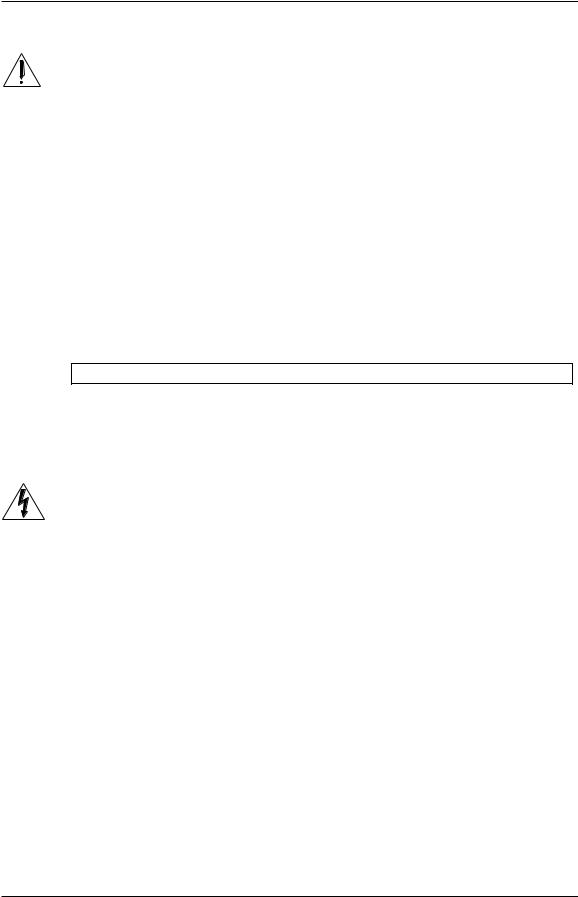
The MIC IN of each channel is a standard female XLR-3 connector. The cable wiring is illustrated below:
Balanced Mic Input
2 1
Hot |
Ground |
3
Cold
Socket (female)
The MIC Input is designed to accept a wide range of balanced or unbalanced low impedance input signals. Each input can provide the +48 volts necessary for phantom-powered microphones on pins 2 and 3; this may be turned on and off with the PHANTOM switch.
 Avoid connecting a mic while the fader is up and phantom power is on. Do not connect a microphone and a line input to the same channel.
Line Inputs
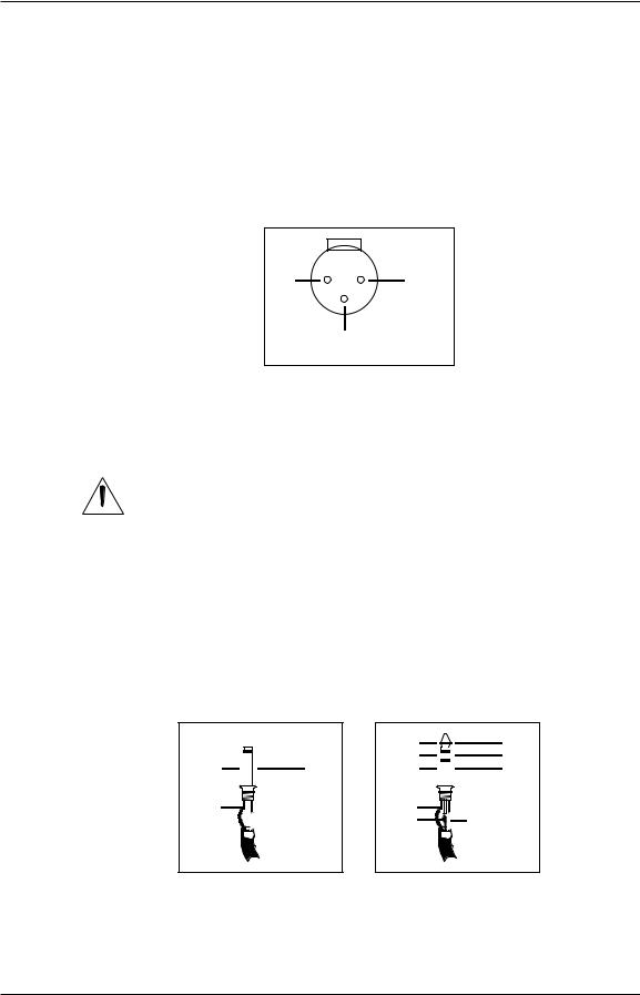
The LINE IN of each channel is a 1/4" jack which will accept balanced or unbalanced line-level sources.
“Line level” means that signals are typically in the 1/3 of a volt to 2-volt range, such as the output of synthesizers, keyboards, CD players, etc. This is in contrast to the much lower levels usually output by microphones (measured in millivolts)
Unbalanced Line Input
Signal 

 Tip
Tip
Ground |
|
Sleeve |
|
|
|
|
|
|
|
|
|
Tip |
 Sleeve
Balanced Line Input
Hot |
|
|
Tip |
|
Cold |
|
|
Ring |
|
Ground |
|
|
Sleeve |
|
|
|
|||
|
|
|
|
|
|
|
|
|
|
Tip |
|
Ring |
Sleeve |
Unlike the low impedance microphone input, this connection provides a high impedance (>10kΩ) to the input signal, enabling most instruments to be plugged straight in without direct boxes or external preamplification. While the output of a standard synthesizer (or other equipment) can be plugged in using a 2-conductor
Studio 32 Reference Manual |
28 |
 Loading...