


ALESIS
Q20
User Manual

Introduction
Thank you for purchasing the Alesis Q20 Professional 20-Bit Master Effects Processor. To take full advantage of of the Q20Õs fuctions, and to enjoy long and trouble free use, please read this userÕs manual carefully.
How To Use This Manual
This manual is divided into the following sections describing the various modes of the Q20. Though we recommend you take time to read through the entire manual once carefully, those having general knowledge about effects devices should use the table of contents and index to reference specific functions while using this device. If you are planning to use the digital I/O, read Chapter 7 carefully.
Chapter 1: Setting Up. Deals with the necessary preparation before using, including connections to other components, such as instruments, mixing consoles, and multitrack recorders, as well as digital connections to ADAT.
Chapter 2: Your First Session with the Q20. A basic introduction to getting the unit up and running, auditioning the factory Programs, adjusting levels, comparing and storing edited Programs.
Chapter 3: Overview. A detailed look at the signal processing capabilities of the Q20, the concepts of multi-effect programming, and a description of the many available effects.
Chapter 4: Making Your Own Programs. A guided tour for programming typical single and multi-effect applications.
Chapter 5: Description of Controls. A ÒdictionaryÓ of all parameters, buttons and connectors, including Global and MIDI mode parameters.
Chapter 6: Advanced Applications. Advanced uses of the Q20, such as MIDI functions, Modulation, Local Generators, footswitches and using Òtap tempoÓ to control delay times.
Chapter 7: Digital Connections. How to use the Q20Õs digital ins and outs in an alldigital studio.
Chapter 8: Troubleshooting. Contains the Troubleshooting Index, maintenance and service information, and MIDI implementation chart.
Conventions
The buttons, knobs, and rear panel connectors are referred to in this manual just as their names appear on the Q20, using all capital letters and in brackets (Examples: [PROGRAM] button, [< BLOCK] button, [VALUE/ENTER] knob/button, [DIGITAL IN] connector, etc.).
When something important appears in the manual, an icon (like the one on the left) will appear in the left margin. This symbol indicates that this information is
vital when operating the Q20.
Q20 Reference Manual |
1 |

2 |
Q20 Reference Manual |

|
Contents |
CONTENTS |
|
1: Setting Up ................................................................................ |
7 |
Unpacking and Inspection....................................................................................... |
7 |
AC Power Hookup.................................................................................................. |
7 |
Line Conditioners and Protectors................................................................. |
7 |
Audio Connections.................................................................................................. |
8 |
Typical Applications................................................................................. |
8 |
Interfacing Directly with Instruments......................................................... |
9 |
Interfacing to a Mixing Console................................................................... |
10 |
When to use Balanced Connectors................................................................ |
15 |
Avoiding Ground Loops............................................................................... |
15 |
MIDI ..................................................................................................................... |
16 |
Digital Connections................................................................................................ |
16 |
Footswitches.......................................................................................................... |
17 |
Advance .................................................................................................... |
17 |
Bypass....................................................................................................... |
17 |
Tap Tempo................................................................................................. |
18 |
2: Your First Session With The Q20 .......................................... |
19 |
Powering Up .......................................................................................................... |
19 |
Setting Levels........................................................................................................ |
19 |
The Value/Enter Knob............................................................................................ |
20 |
Adjusting the Display Contrast .................................................................. |
20 |
Auditioning Internal Programs................................................................................ |
21 |
Switching Between Preset and User Banks .................................................. |
21 |
Example Programs.................................................................................................. |
22 |
96: ÒVerbOfMyDreamsÓ ............................................................................. |
22 |
97: ÒGuitar Rack Ó..................................................................................... |
22 |
98: ÒStereo PlatesÓ ..................................................................................... |
22 |
Adjusting Effects Levels.......................................................................................... |
23 |
Comparing an Edited Program to its Original Settings............................................. |
24 |
Restoring an Edited Program to its Original Settings ............................................... |
24 |
Storing Edited Programs......................................................................................... |
25 |
Auditioning Programs before Storing........................................................... |
25 |
Bypassing Effects................................................................................................... |
26 |
Global Direct Signal Muting................................................................................... |
26 |
3: Overview .................................................................................. |
27 |
The Architecture of the Q20 ................................................................................... |
27 |
What is a Block? ....................................................................................... |
27 |
Selecting and Editing Blocks....................................................................... |
27 |
Routing ÒPatch CordsÓ Between Blocks ....................................................... |
28 |
Quick Route ............................................................................................... |
29 |
Setting the Routing Levels.......................................................................... |
29 |
The L/R IN................................................................................................ |
30 |
Reaching the Outputs - L/R OUT................................................................ |
30 |
Limit Handling...................................................................................................... |
30 |
Equalization.......................................................................................................... |
32 |
Filters ....................................................................................................... |
32 |
Shelving EQs............................................................................................. |
33 |
Single Band EQs......................................................................................... |
33 |
Q20 Reference Manual |
3 |

Contents
Multiband EQs........................................................................................... |
34 |
5 Band Graphic EQ..................................................................................... |
34 |
Resonator................................................................................................... |
35 |
Mono/Stereo Tremolo ................................................................................. |
35 |
Stereo Simulator........................................................................................ |
35 |
Overdrive.................................................................................................. |
36 |
Triggered Panning with Doppler................................................................. |
37 |
Phase Inverter ........................................................................................... |
38 |
Pitch Effects .......................................................................................................... |
39 |
Mono Chorus .............................................................................................. |
39 |
Stereo Chorus............................................................................................. |
39 |
Quad Chorus.............................................................................................. |
40 |
Mono Flanging............................................................................................ |
40 |
Stereo Flanging.......................................................................................... |
41 |
Phasor....................................................................................................... |
41 |
Mono/Stereo Lezlie Cabinet ....................................................................... |
41 |
Pitch Shifter ............................................................................................. |
42 |
Pitch Detune.............................................................................................. |
42 |
Ring Modulator.......................................................................................... |
42 |
Triggered Flanging..................................................................................... |
42 |
Delay.................................................................................................................... |
44 |
Mono Delay and Stereo Delay .................................................................... |
44 |
Ping Pong Delay......................................................................................... |
44 |
Multi Tap Delay........................................................................................ |
44 |
Tap Tempo Mono Delay and Ping Pong......................................................... |
44 |
Sampling................................................................................................... |
45 |
Reverberation........................................................................................................ |
49 |
Mono Room................................................................................................. |
49 |
Room 1....................................................................................................... |
49 |
Hall 1........................................................................................................ |
49 |
Plate 1....................................................................................................... |
49 |
Chamber 1 ................................................................................................. |
49 |
Room 2....................................................................................................... |
49 |
Hall 2........................................................................................................ |
49 |
Plate 2....................................................................................................... |
50 |
Chamber 2 ................................................................................................. |
50 |
Large Plate................................................................................................ |
50 |
Large Room................................................................................................ |
50 |
Spring........................................................................................................ |
50 |
Nonlinear.................................................................................................. |
50 |
Reverse...................................................................................................... |
50 |
Reverb Parameters................................................................................................. |
51 |
Decay........................................................................................................ |
51 |
Damping Ð Hi & Lo .................................................................................... |
51 |
Reverb Density .......................................................................................... |
51 |
Diffusion ................................................................................................... |
51 |
Input High Frequency Roll Off.................................................................... |
52 |
Predelay.................................................................................................... |
52 |
Predelay Mix............................................................................................. |
52 |
Reflection Level and Spread....................................................................... |
52 |
Reverberation Swirl................................................................................... |
52 |
Reverberation Attack................................................................................. |
52 |
Gating ....................................................................................................... |
53 |
4 |
Q20 Reference Manual |

|
|
Contents |
4: Making Your Own Programs ................................................ |
55 |
|
Getting Started...................................................................................................... |
|
55 |
Programming A Single Block................................................................................... |
|
56 |
Type.......................................................................................................... |
|
56 |
Routing...................................................................................................... |
|
57 |
Parameter.................................................................................................. |
|
59 |
Mix............................................................................................................ |
|
60 |
Programming Multiple Blocks................................................................................. |
|
61 |
Defining New Blocks.................................................................................. |
|
61 |
Deleting Unnecessary Routings ................................................................... |
62 |
|
Patching In The New Blocks....................................................................... |
62 |
|
Adjusting Parameters ................................................................................. |
|
62 |
Moving , Swapping and Copying Blocks .................................................................. |
64 |
|
Block Move................................................................................................ |
|
64 |
Block Copy & Paste.................................................................................... |
|
65 |
Changing Effect Types............................................................................................ |
|
66 |
5: Description of Controls........................................................... |
|
67 |
Front Panel ............................................................................................................ |
|
67 |
Input Level ................................................................................................ |
|
67 |
Output Level.............................................................................................. |
|
67 |
LED Meter ................................................................................................. |
|
67 |
Display..................................................................................................... |
|
67 |
Value/Enter............................................................................................... |
|
68 |
Program..................................................................................................... |
|
69 |
Store.......................................................................................................... |
|
70 |
Compare.................................................................................................... |
|
70 |
Bypass....................................................................................................... |
|
71 |
< Block >................................................................................................... |
|
71 |
< Page > .................................................................................................... |
|
71 |
Type.......................................................................................................... |
|
72 |
Parameter.................................................................................................. |
|
72 |
Routing...................................................................................................... |
|
73 |
Mix............................................................................................................ |
|
73 |
Global ....................................................................................................... |
|
74 |
Name ........................................................................................................ |
|
76 |
MIDI ......................................................................................................... |
|
76 |
Modulation................................................................................................ |
|
78 |
Power ........................................................................................................ |
|
78 |
Rear Panel............................................................................................................. |
|
79 |
Power ........................................................................................................ |
|
79 |
MIDI In...................................................................................................... |
|
79 |
MIDI Thru/Out.......................................................................................... |
|
79 |
Bypass......................... |
- Bypass Footswitch............................................... |
79 |
Advance ...................... |
- Program Advance Footswitch ............................... |
79 |
48kHz in...................... |
- Sample Clock Input.............................................. |
79 |
Digital In .................... |
- ADAT Digital Audio In........................................ |
80 |
Digital Out.................. |
- ADAT Digital Audio Out..................................... |
80 |
Digital In .................... |
- S/PDIF Digital Audio In...................................... |
80 |
Digital Out.................. |
- S/PDIF Digital Audio Out ................................... |
80 |
Left/Right In............... |
- Analog Audio In................................................... |
80 |
Left/Right Out ............ |
- XLR Analog Audio Out......................................... |
80 |
Left/Right Out ............ |
- 1/4Ó Analog Audio Out......................................... |
80 |
Q20 Reference Manual |
5 |

Contents |
|
Effect Parameters................................................................................................... |
81 |
Equalization.............................................................................................. |
81 |
Pitch ......................................................................................................... |
82 |
Delay........................................................................................................ |
83 |
Reverberation............................................................................................ |
84 |
6: Advanced Applications .......................................................... |
87 |
MIDI Functions....................................................................................................... |
87 |
Global MIDI Channel................................................................................. |
87 |
Receiving Program Changes........................................................................ |
87 |
Selecting Banks via MIDI........................................................................... |
88 |
Program Change Table ............................................................................... |
88 |
SysEx Storage ............................................................................................ |
89 |
MIDI Thru ................................................................................................. |
90 |
Realtime Modulation Functions .............................................................................. |
91 |
Selecting the Modulator............................................................................. |
91 |
Choosing a Target ...................................................................................... |
92 |
Choosing a Source....................................................................................... |
95 |
Setting the Amplitude ............................................................................... |
95 |
Local Generators ........................................................................................ |
96 |
Footswitch Controls ............................................................................................... |
101 |
Program Advance....................................................................................... |
101 |
Bypassing Effects....................................................................................... |
101 |
Block Bypass via MIDI .............................................................................. |
102 |
Controlling Delay Time via Tap Tempo ...................................................... |
102 |
MIDI Control of Tap Tempo Delay.............................................................. |
103 |
7: Digital Connections ................................................................. |
105 |
Overview .............................................................................................................. |
105 |
Digital Clock Synchronization............................................................................... |
105 |
Connections............................................................................................................ |
107 |
To a Single ADAT ...................................................................................... |
107 |
To Two or More ADATs............................................................................... |
108 |
To Two or More ADATs with a BRC or AI-2................................................. |
109 |
To a Digital Mixer ..................................................................................... |
109 |
To the AI-1 ................................................................................................ |
110 |
From a QuadraSynth or QS-Series Synthesizer........................................... |
110 |
Routings................................................................................................................. |
111 |
To specific ADAT tracks............................................................................. |
111 |
From ADAT through the Q20 back to ADAT................................................ |
112 |
From the QuadraSynth or QS-Series through the Q20 back to ADAT........... |
113 |
8: Trouble-Shooting..................................................................... |
115 |
Trouble-Shooting Index .......................................................................................... |
115 |
Checking the Software Version .............................................................................. |
116 |
Re-initializing ...................................................................................................... |
116 |
Total Reset ............................................................................................................ |
116 |
Error Messages ....................................................................................................... |
117 |
Maintenance/Service ............................................................................................. |
118 |
Refer All Servicing To Alesis...................................................................... |
118 |
Obtaining Repair Service........................................................................... |
118 |
MIDI Implementation Chart .................................................................................. |
119 |
Specifications............................................................................... |
120 |
Effects Processing Index............................................................ |
122 |
6 |
Q20 Reference Manual |

Contents
Q20 Reference Manual |
7 |

Setting Up - Chapter 1
CHAPTER 1
SETTING UP
Unpacking and Inspection
Your Q20 was packed carefully at the factory, and the shipping carton was designed to protect the unit during shipping. Please retain this container in the highly unlikely event that you need to return the Q20 for servicing.
The shipping carton should contain the following items:
¥This instruction manual
¥Alesis Q20 with the same serial number as shown on shipping carton
¥AC Power Cable
¥Alesis warranty card
¥Quick Reference Guide
It is important to register your purchase; if you have not already filled out your warranty card and mailed it back to Alesis, please take the time to do so now.
AC Power Hookup
The Q20 includes an internal universal power supply which is compatible with any line voltage from 90-265 VAC, 50-60 Hz. It also includes a removable IEC power cable suitable for use in the country shipped to.
Note that the Q20 uses a soft power switch which will turn the unit on when plugged in. It is good practice to turn your mixer inputs or returns down while connecting the Q20.
Alesis cannot be responsible for problems caused by using the Q20 or any associated equipment with improper AC wiring.
Line Conditioners and Protectors
Although the Q20 is designed to tolerate typical voltage variations, in todayÕs world the voltage coming from the AC line may contain spikes or transients that can possibly stress your gear and, over time, cause a failure. There are three main ways to protect against this, listed in ascending order of cost and complexity:
¥Line spike/surge protectors. Relatively inexpensive, these are designed to protect against strong surges and spikes, acting somewhat like fuses in that they need to be replaced if theyÕve been hit by an extremely strong spike.
¥Line filters. These generally combine spike/surge protection with filters that remove some line noise (dimmer hash, transients from other appliances, etc.).
¥Uninterruptible power supply (UPS). This is the most sophisticated option. A UPS provides power even if the AC power line fails completely. Intended for computer applications, a UPS allows you to complete an orderly shutdown of a computer system in the event of a power outage, and the isolation it provides from the power line minimizes all forms of interferenceÑspikes, noise, etc.
Q20 Reference Manual |
7 |

Chapter 1 - Setting Up
Audio Connections
The connections between the Q20 and your studio are your musicÕs lifeline, so use only high quality cables. These should be low-capacitance shielded cables with a stranded (not solid) internal conductor and a low-resistance shield. Although quality cables cost more, they do make a difference. Route cables to the Q20 correctly by observing the following precautions:
¥Do not bundle audio cables with AC power cords.
¥Avoid running audio cables near sources of electromagnetic interference such as transformers, monitors, computers, etc.
¥Use balanced cables whenever possible.
¥Do not place cables where they can be stepped on. Stepping on a cable may not cause immediate damage, but it can compress the insulation between the center conductor and shield (degrading performance) or reduce the cableÕs reliability.
¥Avoid twisting the cable or having it make sharp, right angle turns.
¥Never unplug a cable by pulling on the wire itself. Always unplug by firmly grasping the body of the plug and pulling directly outward.
¥Although Alesis does not endorse any specific product, chemicals such as Tweek and Cramolin, when applied to electrical connectors, are claimed to improve the electrical contact between connectors.
Typical Applications
The analog audio inputs and outputs are typically used in one of three ways:
¥from one or two effect/aux send outputs of a mixer, and out to the effect return inputs of the mixer; or,
¥from a line-level instrument (like a guitar or keyboard with either a mono or stereo output), and out to an amplifier or mixer input; or,
¥from the stereo buss outputs of a mixer to a mix-down tape machine or amplifier.
When used with a mono source, the Q20 is placed between the source and the mixer/amplifier. Although the source may be mono, both the [LEFT] and [RIGHT] outputs can be connected to the inputs of a mixer/amplifier if stereo processing effects are desired. Alternatively, you could use the INSERTS on your mixer to Òpatch inÓ only the left or right channel of the Q20. If using the effect sends of a mixer, you have the advantage of sending any of the mixerÕs input channels to the Q20Õs input(s), and have control over the level of each channel being sent.
There are other combinations of input and outputs possible when you begin using the Alesis optical digital input and output. See the ÒDigital ConnectionsÓ section later in this Chapter. For more information on interfacing with other digital audio equipment, see Chapter 7.
8 |
Q20 Reference Manual |
Setting Up - Chapter 1
Interfacing Directly with Instruments
When connecting audio cables and/or turning power on and off, make sure that all devices in your system are turned off and the volume controls are turned down.
The Q20 has two balanced inputs and two balanced outputs. These provide three different (analog) audio hookup options:
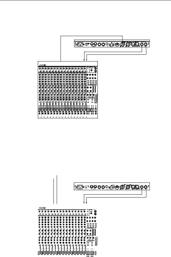
¥Mono. Connect a cable to the [L] INPUT of the Q20 from a mono source, and another cable from the [L] OUTPUT of the Q20 to an amplification system or mixer input.
¥Mono In, Stereo Out. While still using a mono input, you could connect two cables to the [L] and [R] OUTPUTS of the Q20 to a stereo amplification system or two mixer inputs.
|
|
|
|
|
From Instrument or Effects Send |
|
|
|
|
To Amplifier or Mixing Console |
|||||||||||||||||
|
|
|
|
|
|
|
|
|
|
|
|
|
|
|
|
|
|
|
|
|
|
|
|
|
|
|
|
|
|
|
|
|
|
|
|
|
|
|
|
|
|
|
|
|
|
|
|
|
|
|
|
|
|
|
|
|
|
|
|
|
|
|
|
|
|
|
|
|
|
|
|
|
|
|
|
|
|
|
|
|
|
|
|
|
|
|
|
|
|
|
|
|
|
|
|
|
|
|
|
|
|
|
|
|
|
|
|
|
|
|
|
|
|
|
|
|
|
|
|
|
|
|
|
|
|
|
|
|
|
|
|
|
|
|
|
|
|
|
|
|
|
|
|
|
|
|
|
|
|
|
|
|
|
|
|
|
|
|
|
|
|
|
|
|
|
|
|
|
|
|
|
|
|
|
|
|
|
|
|
|
|
|
|
|
|
|
|
|
|
|
|
|
|
|
|
|
|
|
|
|
|
|
|
|
|
|
|
|
|
|
|
|
|
|
|
|
|
|
|
|
|
|
|
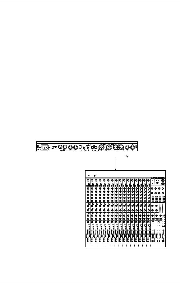
¥Dual Mono or Stereo Source. The Q20 may be used with two different instruments simultaneously, or with a stereo instrument. The hookup is the same; the difference is in the routing used within a program. A program may process the two inputs discretely, using blocks dedicated to a single channel (for example, a delay for a guitar and a gated reverb for a bass), or process them in stereo (for example, with the left and right outputs of a keyboard routed through two reverb blocks). Connect two cables to the [L] and [R] INPUTS of the Q20 from two mono sources or from the stereo output of the instrument, then connect two other cables from the [L] and [R] OUTPUTS of the Q20 to a stereo amplification system or two mixer inputs.
|
|
|
|
|
From Instrument or Effects Send |
|
|
To Amplifier or Mixing Console |
||||||||||||||||||
|
|
|
|
|
|
|
|
|
|
|
|
|
|
|
|
|
|
|
|
|
|
|
|
|
|
|
|
|
|
|
|
|
|
|
|
|
|
|
|
|
|
|
|
|
|
|
|
|
|
|
|
|
|
|
|
|
|
|
|
|
|
|
|
|
|
|
|
|
|
|
|
|
|
|
|
|
|
|
|
|
|
|
|
|
|
|
|
|
|
|
|
|
|
|
|
|
|
|
|
|
|
|
|
|
|
|
|
|
|
|
|
|
|
|
|
|
|
|
|
|
|
|
|
|
|
|
|
|
|
|
|
|
|
|
|
|
|
|
|
|
|
|
|
|
|
|
|
|
|
|
|
|
|
|
|
|
|
|
|
|
|
|
|
|
|
|
|
|
|
|
|
|
|
|
|
|
|
|
|
|
|
|
|
|
|
|
|
|
|
|
|
|
|
|
|
|
|
|
|
|
|
|
|
|
|
|
|
|
|
|
|
|
|
|
|
Note: In most cases when plugging an instrument directly into the Q20 , youÕll use Programs which route the "dry" signal at the input(s) directly to the output(s), where it will be mixed together with the effected signal to achieve the proper wet/dry mix at the Q20's outputs. If the program doesn't include this routing, you will only hear the effected signal by itself. Therefore, it may be necessary to edit such programs to add these "dry" routes when using the Q20 directly with an instrument. (The Factory Preset programs usually include these routes.)
Q20 Reference Manual |
9 |

Chapter 1 - Setting Up
Interfacing to a Mixing Console
The Q20 handles mono or stereo sends at all system levels. The input circuitry of the Q20 can easily handle +4 dBu levels (+17.5 dBu peaks), while having enough input and output gain to interface with the lower -10 dBV signal levels of many recording systems.
The Q20 may be connected to a mixing console in several ways. Usually, it is connected to the auxiliary send and return controls of the mixer. Another method of interfacing is to connect the unit directly to the insert send and return patch points of the channel that is to be effected. Still another way of interfacing the Q20 to a mixer or recording console would be in-line across the output of your mixing console. This last setup would be used only if you needed to effect the entire mix.
Using the Aux Sends
Generally, mixing consoles provide two types of auxiliary sends: pre-fader sends for creating a cue (headphone) mix, and individual, post-fader effect sends. Typically, if a mixer has more than two sends per channel (4, 6 or 8, perhaps), the first two sends are reserved for the cue sends, while the remaining sends are used to feed effects. If you are using a mixer with more than two sends, connect the Q20 using post-fader sends.
Using a mixerÕs aux sends poses a distinct advantage: each channel has its own level control feeding the aux output (and eventually the Q20 input). This allows you to make a mix of any channels you want to go to the effects by using the individual channelsÕ aux send levels on the mixer. Most consoles also have aux master controls, which set the overall level of each aux output.
Coming back from the Q20Õs outputs into the mixer, you have two options:
¥connecting to dedicated return inputs, or
¥connecting to channel inputs.
The former is good if your mixer provides dedicated inputs (called returns) for effect devices like the Q20. If your mixer does not have these, or you have already used them all, consider connecting the Q20 to channel inputs or unused tape returns. You may also want to take advantage of better EQ, panning or automation options on your consoleÕs channel inputs.
10 |
Q20 Reference Manual |

Setting Up - Chapter 1
Setting the Effect/Dry Balance
No matter where you connect the output of the Q20 into the mixer, you are in control of the balance between the mixerÕs channel inputs (the uneffected signal being routed to the aux sends and the Mix) and the effect returns coming from the Q20. The effect returns generally should only contain effected signal, and not have any uneffected signal mixed with it (since these two signals are blended together at the mixer).
If the Program you are using has the L/R IN connected to the L/R OUT, you may be getting some dry, uneffected signal at the return. Generally, this is not desirable when using the Q20 with a mixer, since the "dry" signal is already being heard through the original channelÕs fader. Therefore, in a mixer application you will want to cut the Q20Õs ProgramÕs path which connects the inputs to the outputs. This can be done in three ways:
¥Go to the Mix parameters to bring down the direct level
¥Go to the Routing function of each program and remove the patch cords connecting the inputs to the outputs
¥Turn on the Global Direct Signal Mute function. This is the easiest method.
Most Preset Programs route the L/R IN signal to the L/R OUT.When connecting to a mixerÕs aux sends and returns. the Global Direct Signal Mute should be set to MUTE.
To remove all direct routings of inputs to outputs on all Programs simultaneously:
Press [GLOBAL].
The [GLOBAL] LED will be lit.
Press [< PAGE] once.
This selects Global Page 9. The display will read:
GLOBAL DIRECT SIGNAL: ON
Turn the [VALUE/ENTER] knob to the right until the display reads ÒON.Ó
The next Program recalled which has the inputs routed to the outputs will not display the patch cords for these connections nor will you hear any direct uneffected signal at the outputs.
Q20 Reference Manual |
11 |
Chapter 1 - Setting Up
Mono In - Stereo Out. If you only want to feed the Q20 a mono input, but wish to connect both of its outputs back to the mixer, you will need three audio cables. Connect a cable from an effect send to the [L] INPUT of the Q20, another cable from the [L] OUTPUT of the Q20 to an effect return or other mixer input, and another cable from the [R] OUTPUT of the Q20 to an adjacent mixer input.
Left Input
Left and
Right
Outputs
Aux Send 3 |
Stereo Aux Returns |
Stereo In - Stereo Out. This connection is similar to the one described above. However, by utilizing two sends from the mixer, we add one more cord and can now send a stereo signal to the Q20Õs inputs. Example, if you connected effect sends 3 and 4 to the [L] and [R] INPUTS, and had a stereo instrument (such as a keyboard) connected to two channel inputs of the mixer (either one panned hard left and hard right), you would send the left channel to send 3 and the right channel to send 4. Alternatively, you could have two discrete effect sends between the Left and Right channel, and process each separately within the Q20. For example, the Left channel (from send 3) could be a chorus, and the Right (from send 4) could be a reverb. This is similar to Dual Mono, described earlier.
|
|
|
|
|
|
|
|
|
|
|
|
|
|
|
|
|
|
|
|
|
|
|
|
Left Input |
|
|
|
Right Input |
|||||||
|
|
|
|
|
|
|
|
|
|
|
|
|
|
|
|
|
|
|
|
|
|
|
|
|
|
|
|
|
|
|
|
|
|
|
|
|
|
|
|
|
|
|
|
|
|
|
|
|
|
|
|
|
|
|
|
|
|
|
|
|
|
|
|
|
|
|
|
|
|
|
|
Left and
Right
Outputs
|
|
|
|
Aux Send 3 |
|
|
|
|
|
Aux Send 4 |
|
|
Stereo Aux Returns |
|||||||||||||||||||||||||||||||||||||||||||||
|
|
|
|
|
|
|
|
|
|
|
|
|
|
|
|
|
|
|
|
|
|
|
|
|
|
|
|
|
|
|
|
|
|
|
|
|
|
|
|
|
|
|
|
|
|
|
|
|
|
|
|
|
|
|
|
|
|
|
|
|
|
|
|
|
|
|
|
|
|
|
|
|
|
|
|
|
|
|
|
|
|
|
|
|
|
|
|
|
|
|
|
|
|
|
|
|
|
|
|
|
|
|
|
|
|
|
|
|
|
|
|
|
|
|
|
|
|
|
|
|
|
|
|
|
|
|
|
|
|
|
|
|
|
|
|
|
|
|
|
|
|
|
|
|
|
|
|
|
|
|
|
|
|
|
|
|
|
|
|
|
|
|
|
|
|
|
|
|
|
|
|
|
|
|
|
|
|
|
|
|
|
|
|
|
|
|
|
|
|
|
|
|
|
|
|
|
|
|
|
|
|
|
|
|
|
|
|
|
|
|
|
|
|
|
|
|
|
|
|
|
|
|
|
|
|
|
|
|
|
|
|
|
|
|
|
|
|
|
|
|
|
|
|
|
|
|
|
|
|
|
|
|
|
|
|
|
|
|
|
|
|
|
|
|
|
|
|
|
|
|
|
|
|
|
|
|
|
|
|
|
|
|
|
|
|
|
|
|
|
|
|
|
|
|
|
|
|
|
|
|
|
|
|
|
|
|
|
|
|
|
|
|
|
|
|
|
|
|
|
|
|
|
|
|
|
|
|
|
|
|
|
|
|
|
|
|
|
|
|
|
|
|
|
|
|
|
|
|
|
|
|
|
|
|
|
|
|
|
|
|
|
|
|
|
|
|
|
|
|
|
|
|
|
|
|
|
|
|
|
|
|
|
|
|
|
|
|
|
|
|
|
|
|
|
|
|
|
|
|
|
|
|
|
|
|
|
|
|
|
|
|
|
|
|
|
|
|
|
|
|
|
|
|
|
|
|
|
|
|
|
|
|
|
|
|
|
|
|
|
|
|
|
|
|
|
|
|
|
|
|
|
|
|
|
|
|
|
|
|
|
|
|
|
|
|
|
|
|
|
|
|
|
|
|
|
|
|
|
|
|
|
|
|
|
|
|
|
|
|
|
|
|
|
|
|
|
|
|
|
|
|
|
|
|
|
|
|
|
|
|
|
|
|
|
|
|
|
|
|
|
|
|
|
|
|
|
|
|
|
|
|
|
|
|
|
|
|
|
|
|
|
|
|
|
|
|
|
|
|
|
|
|
|
|
|
|
|
|
|
|
|
|
|
|
|
|
|
|
|
|
|
|
|
|
|
|
|
|
|
|
|
|
|
|
|
|
|
|
|
|
|
|
|
|
|
|
|
|
|
|
|
|
|
|
|
|
|
|
|
|
|
|
|
|
|
|
|
|
|
|
|
|
|
|
|
|
|
|
|
|
|
|
|
|
|
|
|
|
|
|
|
|
|
|
|
|
|
|
|
|
|
|
|
|
|
|
|
|
|
|
|
|
|
|
|
|
|
|
|
|
|
|
|
|
|
|
|
|
|
|
|
|
|
|
|
|
|
|
|
|
|
|
|
|
|
|
|
|
|
|
|
|
|
|
|
|
|
|
|
|
|
|
|
|
|
|
|
|
|
|
|
|
|
|
|
|
|
|
|
|
|
|
|
|
|
|
|
|
|
|
|
|
|
|
|
|
|
|
|
|
|
|
|
|
|
|
|
|
|
|
|
|
|
|
|
|
|
|
|
|
|
|
|
|
|
|
|
|
|
|
|
|
|
|
|
|
|
|
|
|
|
|
|
|
|
|
|
|
|
|
|
|
|
|
|
|
|
|
|
|
|
|
|
|
|
|
|
|
|
|
|
|
|
|
|
|
|
|
|
|
|
|
|
|
|
|
|
|
|
|
|
|
|
|
|
|
|
|
|
|
|
|
|
|
|
|
|
|
|
|
|
|
|
|
|
|
|
|
|
|
|
|
|
|
|
|
|
|
|
|
|
|
|
|
|
|
|
|
|
|
|
|
|
|
|
|
|
|
|
|
|
|
|
|
|
|
|
|
|
|
|
|
|
|
|
|
|
|
|
|
|
|
|
|
|
|
|
|
|
|
|
|
|
|
|
|
|
|
|
|
|
|
|
|
|
|
|
|
|
|
|
|
|
|
|
|
|
|
|
|
|
|
|
|
|
|
|
|
|
|
|
|
|
|
|
|
|
|
|
|
|
|
|
|
|
|
|
|
|
|
|
|
|
|
|
|
|
|
|
|
|
|
|
|
|
|
|
|
|
|
|
|
|
|
|
|
|
|
|
|
|
|
|
|
|
|
|
|
|
|
|
|
|
|
|
|
|
|
|
|
|
|
|
|
|
|
|
|
|
|
|
|
|
|
|
|
|
|
|
|
|
|
|
|
|
|
|
|
|
|
|
|
|
|
|
|
|
|
|
|
|
|
|
|
|
|
|
|
|
|
|
|
|
|
|
|
|
|
|
|
|
|
|
|
|
|
|
|
|
|
|
|
|
|
|
|
|
|
|
|
12 |
Q20 Reference Manual |
Setting Up - Chapter 1
Using Inserts
By using individual channel inserts, you can dedicate the Q20 to a specific channel (or pair of channels) on the mixer. The Insert connections on the back of the mixer provide a way of ÒinsertingÓ external processing equipment into the signal path. The insert occurs after the input amplifier, and before the main fader; essentially it is the same as connecting the source (instrument or microphone) into the Q20 before the mixerÕs channel input. However, some mixing consoleÕs inserts come after the EQ section, and may therefore be different from the original signal.
Usually, insert connections require a special, stereo-splitting Y-cord to be connected (one stereo plug provides both send and return while two mono plugs connect separately to an input and output). These are known as TRS connectors (tip-ring- sleeve). The tip of the stereo plug typically carries the send or output of the insert jack, while the ring carries back the return. The sleeve represents a common ground for both signals. Check the manual of your mixer because some are wired differently (for example, having two separate jacks for send and receive).
Mono. This involves connecting a 1/4" TRS (tip-ring-sleeve) to the Insert jack of a single channel on a mixing console. The other end of the cable (which splits into two, 1/4" mono connectors) are connected to the [L] INPUT and [L] OUTPUT, respectively. If you do not hear any audio after making these connections, swap the input and output cables at the Q20, as these may be wired backwards. If the cable is color-coded, usually the red jack represents the send (which connects to the Q20Õs INPUT) and black is the return (which connects to the OUTPUT).
|
|
|
|
|
|
|
|
|
|
|
|
|
Left Input |
|
|
|
|
|
|
|
|
|
Left Output |
||
|
|
|
|
|
|
|
|
|
|
|
|
|
Channel |
Insert |
Q20 Reference Manual |
13 |

Chapter 1 - Setting Up
Stereo. In the case where a stereo instrument, such as a keyboard or sampler, is connected to two separate channels of a mixing console, you will need two 1/4" TRS cables, one for each channel. The connection is made in a similar fashion as described above.
Right |
Right |
Input |
Output |
Left |
Left |
Input |
Output |
Left |
Right |
Insert |
Insert |
Using Main Outputs
When you want to effect everything on the mixer, you can connect the Q20 between the mixerÕs outputs and the amplifierÕs or tape machineÕs inputs. This is done by using two cables to connect the Left and Right Main Outputs of the mixing console to the [L] and [R] INPUTs of the Q20. The [L] and [R] OUTPUTs of the Q20 are then connected to a stereo amplifier, or two input channels of another mixing console (for sub-mixing applications).
Left |
|
Right |
Output |
Output |
|
Left |
Right |
|
Input |
Input |
|
Left |
Right |
|
Master |
Master |
|
Out |
Out |
|
Power |
|
Power |
|
||
Amp |
|
Amp |
Left |
|
Right |
Input |
|
Input |
|
|
|
Out to Speakers
14 |
Q20 Reference Manual |

Setting Up - Chapter 1
When to use Balanced Connectors
There are three options for connecting analog audio to the Q20: 1/4Ó unbalanced, 1/4Ó balanced (TRS) and XLR balanced. If your source and destination use balanced connectors, you should try to stay balanced throughout the chain. Balanced cables have a higher signal level and have the ability to cancel out hum and noise, which can make your mixes quieter. XLR connectors have the added bonus of locking into place, a good idea if you need to move your effects rack from place to place.
Keeping this in mind, your order of preference when connecting the Q20 to a mixer should be to use the XLR connectors first, then to use balanced 1/4Ó cables, then unbalanced 1/4Ó cables if your mixer doesnÕt have balanced sends and receives.
Avoiding Ground Loops
In todayÕs complex studio there are many opportunities for ground loop problems to occur. These show up as hums, buzzes or sometimes radio reception, and can occur if a piece of equipment ÒseesÓ two or more different paths to ground. While there are methods to virtually eliminate ground loops and stray radio frequency interference, most of the professional methods are expensive and involve installing a separate power source just for the sound system. Here are some easy helpful hints that a professional studio installer might use to zap those stray hums and buzzes.
KEEP ALL ELECTRONICS OF THE SOUND SYSTEM ON THE SAME AC ELECTRICAL CIRCUIT. Most stray hums and buzzes happen as a result of different parts of the sound system being plugged into outlets of different AC circuits. If any noise generating devices such as air conditioners, refrigerators, neon lights, etc., are already plugged into one of these circuits, you then have a perfect condition for stray buzzes. Since most electronic devices of a sound system donÕt require a lot of current (except power amplifiers), itÕs usually safe to run a multi-outlet box (or two) from a SINGLE wall outlet, and plug in all of the components of your system there.
KEEP AUDIO WIRING AS FAR AWAY FROM AC WIRING AS POSSIBLE. Many hums come from audio cabling being too near AC wiring. If a hum occurs, try moving the audio wiring around to see if the hum ceases or diminishes. If itÕs not possible to separate the audio and AC wiring in some instances, make sure that the audio wires donÕt run parallel to any AC wire (they should only cross at right angles, if possible).
TO ELIMINATE HUM IF THE ABOVE HAS FAILED:
A)Disconnect the power from all outboard devices and tape machines except for the mixer and control room monitor power amp.
B ) Plug in each tape machine and outboard effects device one at a time. If possible, flip the polarity of the plug of each device (turn it around in the socket) until the quietest position is found.
C)Make sure that all of the audio cables are in good working order. Cables with a detached ground wire will cause a very loud hum!!
D)Keep all cables as short as possible, especially in unbalanced circuits.
If the basic experiments donÕt uncover the source of the problem, consult your dealer or technician trained in proper studio grounding techniques. In some cases, a Òstar groundingÓ scheme must be used, with the mixer at the center of the star providing the shield ground on telescoping shields, which do NOT connect to the chassis ground of other equipment in the system.
Q20 Reference Manual |
15 |

Chapter 1 - Setting Up
MIDI
MIDI is an internationally-accepted protocol that allows music-related data to be conveyed from one device to another. The MIDI connections on the Q20 provide five different functions:
¥To recall programs using MIDI program change messages
¥To control various parameters inside the Q20 in realtime via MIDI controllers (example: A keyboardÕs mod wheel, or pedals, etc.)
¥To convert MIDI Clock messages into delay settings on Tap Tempo Delay Blocks
¥To send and receive SysEx (System Exclusive) dumps of individual programs or the entire bank of programs for storage and retrieval purposes
¥To pass-on MIDI information thru the Q20 to another MIDI device.
To connect the Q20Õs MIDI ports to another MIDI device:
Connect a MIDI cable from the Q20Õs MIDI [THRU/OUT] connector to the MIDI IN connector of the other MIDI device.
Connect another MIDI cable from the Q20Õs MIDI [IN] connector to the other MIDI deviceÕs MIDI OUT connector.
For more information about MIDI, refer to Chapter 6.
Digital Connections
Digital connections provide better fidelity than the analog inputs and outputs because you avoid converting the audio from digital to analog (say from a digital mixer), then to digital (Q20 input), then analog (Q20 output), then digital again (back into the mixer).
The Q20 provides two formats for direct digital connections: ADAT Optical and S/PDIF. The Alesis Optical interface provides two EIAJ fiber optic connectors for [DIG IN] and [DIG OUT]. These connectors use a proprietary Alesis multichannel format first introduced with the ADAT Multitrack Recorder. The Q20 can send and/or receive digital audio directly to/from an ADAT (or other devices which use the same optical interface). The S/PDIF inputs and outputs are provided on coaxial (phono) jacks and conform to the consumer digital interface format (Sony/Philips Digital Interface Format).
The proprietary Alesis Optical format carries up to 8 audio channels on a single fiber optic cable. Since the Q20 has two channels (left and right), you may choose two of the incoming 8 channels for the Q20 to process or output.
ADAT Optical fiber optic cables of various lengths are available from your Alesis dealer. The shorter the cable, the better. The OC cable is 5 meters long (16'4") and is the maximum length recommended. For S/PDIF connection, you should use good quality video-type phono cables.
16 |
Q20 Reference Manual |

Setting Up - Chapter 1
Footswitches
On the rear panel you will find two footswitch jacks labeled [ADVANCE] and [BYPASS]. Any momentary single-pole/single-throw footswitch, normally open or normally closed, will work for the two footswitch functions. These should be plugged in prior to power-up so that the Q20 can configure itself for the type of footswitch being used.
Advance
The [ADVANCE] jack lets you scroll through the Programs in memory by advancing to the next higher numbered Program each time the connected footswitch is pressed. The Q20 will Òwrap-aroundÓ whenever it reaches the end of available Programs and the Advance footswitch is pressed again. You can set a range of Programs to be used, thereby cutting off other Programs from being recalled in this manner. For example, if you set the range to be User 0-10 through User 0-24, only Programs within this range will be recalled using the Advance footswitch. If Program 0-24 is selected and the footswitch is pressed again, Program 0-10 is recalled.
To adjust the Advance FootswitchÕs set of Programs:
Press [GLOBAL].
The [GLOBAL] LED will light.
Press [PAGE >] once.
This selects page 2, and the display will read:
FOOTSWITCH: Preset00 TO User1-99
Turn the [VALUE/ENTER] knob to adjust the Program number to begin the range (Preset 00 ÑÊ99, User 0-00 Ñ 1-99).
Press [PAGE >] once and use the [VALUE/ENTER] knob to adjust the Program number to end the range (Preset 00 ÑÊ99, User 0-00 Ñ 1-99).
Bypass
The Bypass footswitch jack lets you turn the Bypass function on and off from a connected footswitch. When pressed, the [BYPASS] LED will light, indicating that Bypass mode is enabled. When pressed again, the [BYPASS] LED will turn off.
For more information about Bypass mode, see Chapters 2 and 5.
Q20 Reference Manual |
17 |

Chapter 1 - Setting Up
Tap Tempo
Either footswitch jack can be used to provide a tap tempo source for setting delay time, provided the selected Program uses one of the two available tap tempo delay types. This requires that you have defined an Effect Block as one of the two Tap Tempo delay types, and that the desired footswitch jack has been selected for controlling tap tempo. To select a footswitch jack for use with a Tap Tempo Delay:
Press [GLOBAL].
The [GLOBAL] LED will light.
Press [< PAGE] twice to select Global Page 8.
The display will read:
TAP TEMPO FOOTSWITCH: NONE
Turn the [VALUE/ENTER] knob to select either the ADVANCE or BYPASS footswitch jack, depending on which one you wish to use to control tap tempo.
Note that some programs can override these footswitch settings by re-assigning pedals as Local Generator Sources in the Modulation pages. See Chapter 6 for more information.
18 |
Q20 Reference Manual |
Your First Session with the Q20 - Chapter 2
CHAPTER 2
YOUR FIRST SESSION
WITH THE Q20
Powering Up
After making your connections, turn on the systemÕs power using this procedure:
Before turning on the Q20Õs power, check the following items:
¥Have all connections been made correctly?
¥Are the volume controls of the amplifier or mixer turned down?
Turn on the [POWER] switch on the front panel of the Q20.
Upon power-up, the Q20 will display the last selected Program, and the [PROGRAM] buttonÕs LED will be lit. If this Program has been edited, the display will indicate this by showing the word ÒEDITEDÓ, and by flashing the Program Number and Name in the upper display.
Turn on the power of the amplifier/mixer, and adjust the volume.
Setting Levels
Proper setting of the [INPUT LEVEL] and [OUTPUT] knobs is crucial in order to achieve the maximum signal-to-noise ratio (the concentric knobs allow the Left and Right Input levels to be adjusted separately). As a good starting point, set both input and output level controls at about 2 o'clock or 65% of full. This will decrease the possibility of overload distortion and keep the amount of background noise to a minimum.
For quietest operation, you should adjust the level of the source being sent to the Q20 so that the green [-3dB] LEDs in the Q20Õs peak meter flash, but not so loud
that the red [CLIP] LEDs turn on. A nominal input sound make the -12dB LED turn on
Note: The Input and Output level controls effect the analog inputs and outputs only. If you need to attenuate the digital inputs, you can do this in Page 2 of the Routing pages. See Chapter 4 for more information.
Q20 Reference Manual |
19 |

Chapter 2 - Your First Session with the Q20
The Value/Enter Knob
Located just to the right of the custom LCD display, the [VALUE/ENTER] knob is used to select Programs and adjust parameter values that appear in the display. However, it is not just a knob, it is also a button. Depending on what parameter you are editing, the [VALUE/ENTER] knob will work in either one of two ways:
Immediate. The desired value is selected by turning the [VALUE/ENTER] knob, and immediately takes effect. This is the case when adjusting most parameters.
Deferred. The desired value is selected by turning the [VALUE/ENTER] knob, but the new value will only take effect after the [VALUE/ENTER] button has been pressed. The newly selected value will flash in the display until it is selected in this manner. If you change the parameter back to its original setting, the value in the display will not flash. Also, if you go to another Page, or select another Function (by pressing any button), the parameter will be left unchanged. If you went back to look at the previous parameter, it will be set back to its original setting. This mode is used for parameters that cause architectural changes such as changing a BlockÕs function, effect type, and routing signals.
The [VALUE/ENTER] button can also be used to step through Pages in the currently selected mode. Except when a value is flashing on and off in the display, the [VALUE/ENTER] button ordinarily doubles for the [PAGE >] button. If you change the value of a parameter that uses Òdeferred mode,Ó, you must press the [VALUE/ENTER] button to enter the new value (the display will stop flashing), and then you can press it again to move to the next Page (or to the next parameter, if more than one parameter appears in the display). This is a feature for power users who want to be able to move around the various pages quickly and make changes as fast as possible.
Unique Exception: When editing the Delay Time parameter of a Delay Block set to either Tap Tempo Mono Delay or Tap Tempo Ping Pong, the [VALUE/ENTER] button is used to ÒtapÓ in a tempo . See Chapter 6 for more information.
Adjusting the Display Contrast
Occasionally, the characters in the LCD display may be difficult to read, depending on the viewing angle and existing lighting conditions. In such a situation, adjust the contrast of the LCD display using the following procedure.
Press [GLOBAL].
The display will go to the Global Mode Page 1.
ADJUST DISPLAY CONTRAST: 5
Adjust the contrast by turning the [VALUE/ENTER] knob.
The displayÕs contrast and its value in the display will change.
20 |
Q20 Reference Manual |

Your First Session with the Q20 - Chapter 2
Auditioning Internal Programs
You can audition the Programs in the Q20 by using the [VALUE/ENTER] knob or the front panel buttons, whenever the Q20 is in Program mode (the [PROGRAM] buttonÕs LED will be lit).
To select a Program using the [VALUE/ENTER] knob:
Press [PROGRAM].
The [PROGRAM] buttonÕs LED will light.
Turn the [VALUE/ENTER] knob.
Note: The [VALUE/ENTER] knob has two modes when used for selecting Programs: Direct and Deferred. Direct mode immediately recalls the displayed Program as you turn the [VALUE/ENTER] knob. Deferred mode lets you scroll through the Programs in the display by turning the [VALUE/ENTER] knob, but you must press the [VALUE/ENTER] button to actually recall a Program. For more information on choosing between Direct and Deferred mode, see Chapter 5.
To select a Program using the front panel buttons:
Hold the [PROGRAM] button.
Use the [1] through [0] buttons to directly select Programs 00 through 99.
These are the right-most ten buttons on the front panel, which double for
[BLOCK >], [TYPE], [ROUTING], etc.
The top line of the display will change to indicate the currently selected Program number (from 00-99) and its name.
PROG: Preset 00 "Concert Hall "
PROGRAM
The left side of the display always indicates the currently selected Program number (00 Ð 99). Directly beneath the two-digit Program number, the word ÒPRESETÓ will appear when the Preset bank is selected.
PRESET
Switching Between Preset and User Banks
There are three banks in the Q20: Preset, User 0 and User 1. They each contain 100 Programs. However, the Preset bank cannot be permanently changed. You can edit the Preset Programs, but you can store them only in the User banks. To switch between the Preset and User banks, follow these steps:
Press and hold the [PROGRAM] button.
Use the [< BLOCK] and [< PAGE] buttons to select either PRESET or USER. Press the [< PAGE] again to toggle between the two User banks.
The currently selected Bank will be displayed in the top row of the LCD display. Also, when the Preset Bank is selected, the display will show the word ÒPRESETÓ beneath the PROGRAM number in the lower left corner.
Q20 Reference Manual |
21 |

Chapter 2 - Your First Session with the Q20
Example Programs
The following are descriptions of the three example Programs in the Preset bank.
96: “VerbOfMyDreams”
This Program is fairly simple in design, using only 3 Blocks to provide EQ, Delay and Reverb. It is designed for a mono audio source to be connected to the [R] INPUT. In the display, you can see the R IN routed to the first Block, which is defined as a 3-Band Parametric EQ. The M output of the EQ then is routed to the next Block, which is a Mono Delay. The M output of the Delay is then routed to the next Block, which is a Room 2 Reverb. The L output of the Reverb is routed to the L OUT while the R output of the Reverb is routed to the R OUT. Also, the R IN is routed to both the L and R OUT, to combine the original dry signal with the wet signal coming from Block #3.
The EQ Block is used to tailor the sound before further processing occurs. You should make adjustments here based on the signal you feed through it; if the higher frequencies of the input signal do not sound as good through the Reverb as the mids and lows, try attenuating them in the EQ. The Delay is used to ÒthickenÓ the sound by adding a few very fast echoes. The Reverb adds ambiance, as if you were in a large chamber, and completes the total effect.
Using the Mix function, you can adjust the output level of the Reverb Block and the Direct Signal to create the balance you are looking for.
97: “Guitar Rack”
This Program includes two Pitch Blocks feeding a delay Block, into another Pitch Block, then into a Reverb Block, and finally yet another Pitch Block. This is a prime example of the flexibility the Q20 offers to programmers. The Program creates a thick, swirling, ambient effect that greatly enhances an electric guitarÕs sound.
The R IN is routed to Blocks 1 and 2, as well as the L and R OUT. The first two Pitch Blocks are defined as Pitch Detune type, but are set to different detune amounts to create a thicker sound. The Delay Block is a Mono Delay which provides a very quick Òslap backÓ by using a small delay time and no feedback. The third Pitch Block provides a Stereo Chorus which swirls the detuned, delay signal and feeds directly to the outputs. The Delay BlockÕs output is also fed into a Hall 1 Reverb which provides ambience to the un-chorused signal. The ReverbÕs stereo signals are routed to the Q20Õs outputs and mixed with the Stereo ChorusÕs signals. Meanwhile, the ReverbÕs mono output feeds a Stereo Flanger whose stereo signals are also combined with the Stereo Chorus, Reverb and the original input signal at the outputs. Again, use the Mix parameters to create just the balance you want.
98: “Stereo Plates”
This Program is very simple. It routes the L and R IN through separate stereo type Reverb Blocks (Plate 1 type, to be precise). Both stereo signals coming out of the two Reverb Blocks feed the L/R OUT. This creates a very clean stereo reverb effect thatÕs great for vocals. Play around with the Predelay and Decay parameters to adjust the attack and length of the reverb.
22 |
Q20 Reference Manual |

Your First Session with the Q20 - Chapter 2
Adjusting Effects Levels
Although we may not want to get started editing Programs just yet (thatÕs left for Chapter 4), it is usually necessary to have immediate control over the output levels of each Effect Block, as well as the amount of direct level going from the inputs to the outputs. These are found within Mix mode.
To adjust a ProgramÕs effect levels:
Press the [MIX] button.
The [MIX] buttonÕs LED will light.
Use the [< BLOCK >] buttons to select any of the active Blocks in the display.
If the selected Block is routed to the L/R Outputs, the display will read:
LEVEL TO L/R:RVB=100%
The letters RVB in the display example above indicate the selected Block is of the Reverberation type. Other types are: EQ for Equalization, PCH for Pitch and DLY for Delay.
Turn the [VALUE/ENTER] knob to adjust the BlockÕs Level to the L/R Outputs, from 0Ð100%.
If the selected Block is not routed to the L/R Outputs, this setting will be ÒNONEÓ and you will not be able to adjust the value.
Press [PAGE >] to advance to Mix Page 2 and adjust the Direct Level from Input.
The display will read:
DIRECT LEVEL FROM INPUT: 100%
Turn the [VALUE/ENTER] knob to adjust how much of the dry (uneffected) signal you wish to hear at the Q20Õs outputs, from 0Ð100%.
If the L/R Inputs are not routed to the L/R Outputs, this setting will be ÒNONEÓ and you will not be able to adjust the value since there is no direct signal.
If the Global Direct Signal Mute function is turned on, the Direct Level From Input parameter will have no audible effect, although its setting is remembered when you store the Program.
Press [PAGE >] to advance to Mix Page 3 and adjust the Master Effects Level.
MASTER EFFECTS LEVEL: 100%
Use the [VALUE/ENTER] knob to adjust the Master Effects Level to the L/R Outputs, from 0Ð100%.
This parameter comes between the combined Effect BlocksÕ outputs and the Q20Õs outputs, and controls the output levels of all active Blocks that are routed to the L/R Outputs simultaneously. However, it does not change the individual output levels of Effect Blocks that are routed internally (i.e. to other Blocks).
Q20 Reference Manual |
23 |

Chapter 2 - Your First Session with the Q20
Use the [< BLOCK >] buttons to select other Blocks, and adjust their levels, as described above.
Mix parameters affect the Program and are only temporary unless the Program is stored into memory before a another Program is recalled. See later in this Chapter for more about comparing and storing edited Programs.
Comparing an Edited Program to its Original Settings
PROGRAM
EDITED
The left side of the display always indicates the currently selected Program. Once a Program has been edited, the word ÒEDITEDÓ appears in the lower left part of the display, just below the Program Number indicator. If the [PROGRAM] button is pressed (the [PROGRAM] buttonÕs LED will light), the display will also indicate the Program has been altered from its stored version by flashing the Program number and name in the upper section of the display.
By pressing [COMPARE], you can temporarily access the original version of the Program you are editing; that is, the last Program saved to the currently selected location number. This allows you to hear the differences created by changing parameters in the Program.
While you are in Compare mode, the [COMPARE] buttonÕs LED will be lit. Also, you cannot adjust any of the Type, Routing, Parameter, Modulation settings. However, you can move around the various pages and view these original settings and therefore see the actual differences in settings you have changed.
Pressing [COMPARE] a second time exits Compare mode; the [COMPARE] buttonÕs LED will turn off and the edited version of the Program will be accessed. You can go in and out of Compare mode as often as you like, as long as the display indicates ÒEDITEDÓ (i.e., if the Program hasnÕt been edited yet, there is nothing to compare it to).
Restoring an Edited Program to its Original Settings
If you decide to abort the changes you have made to a Program, this can be done in two easy steps.
To restore an edited Program to its previous, unedited version:
Press [PROGRAM] to select Program mode.
The [PROGRAM] buttonÕs LED will light, and the display will flash the selected Program number and name.
Press the [VALUE/ENTER] button.
This recalls the last stored version of the currently selected Program number, and the word ÒEDITEDÓ disappears from the display. Consequently, any changes you had made to the Program before recalling are lost. unless you stored the edited Program into memory.
24 |
Q20 Reference Manual |

Your First Session with the Q20 - Chapter 2
Storing Edited Programs
Once you are satisfied with the changes you have made to a Program, or are creating a new Program from scratch, you will need to store your edited Program back into memory. The Q20 will store the currently selected Program in memory (which is retained when the unit is turned off). If you edit a Program, the changes you made will still be there the next time you switch on the unit, even if you hadnÕt stored the edited Program into memory yet. However, if you select another Program from memory before storing the edited Program, your changes will be lost. Although the Q20 has two banks (Preset and User), you can only store Programs in the User bank.
The Preset bank cannot be permanently changed. If you edit a Program selected from the Preset bank, you will be able to make changes, but when you attempt to Store the edited Program, it will be stored into the User bank (in the selected number location).
To store an edited Program into memory:
Press the [STORE] button.
The [STORE] buttonÕs LED will light. The display will read:
STORE AT: X-YY "nnnnnnnnnnnnnn"
Éwhereby X is User Bank 0 or 1, YY is a Program number from 0 to 99 and nnnn is the name of the program that will be overwritten. Both the Program number and name will be flashing.
Turn the [VALUE/ENTER] knob to select the Program number location in the User bank to store the edited Program into.
Press the [VALUE/ENTER] button.
The display will momentarily read:
PROGRAM STORED
After storing, the User Program location you chose will automatically be selected and shown in the display (example: if you edited Program 13 and stored it into location 25, Program 25 will be selected).
Auditioning Programs before Storing
Here is a handy trick you can use in a sticky situation. LetÕs say youÕve just created a killer Program and you want to store it but you donÕt know where. If you are using Deferred Mode (Program mode, Page 2), you can scroll through a list of Programs and view their names without actually recalling them (which would result in losing your edited Program). If you want to hear what a Program sounds like, simply press the [COMPARE] button to audition a Program without selecting it. Once youÕve found the location you want to store into, you can simply press [STORE] twice to replace the selected Program with your newly created Program.
Q20 Reference Manual |
25 |

Chapter 2 - Your First Session with the Q20
Bypassing Effects
At any time you can bypass all effects at once, thereby allowing the direct signal to pass through the Q20 unchanged. This can be done in two ways:
¥by pressing the [BYPASS] button on the front panel; or,
¥by connecting a footswitch to the [BYPASS] jack and pressing the footswitch.
Each time either the [BYPASS] button is pressed, or the footswitch connected to the [BYPASS] jack is pressed, Bypass mode is toggled on and off again. When Bypass mode is turned on, the [BYPASS] button's LED will be lit.
When Bypass is enabled, all Effect Blocks are momentarily disabled and will not have audio routed from them to the outputs. However, if the Program does not route the L/R Inputs directly to the L/R Outputs, you will not hear anything.
In order for the Bypass mode to function correctly, make sure the L/R Inputs are routed to the L/R Outputs and that the Global Direct Signal Mute function is turned off (see below). If the inputs are not routed directly to the outputs, the [BYPASS] button acts more like a ÒmuteÓ since nothing will be heard when it is enabled.
Global Direct Signal Muting
The purpose of this feature is to satisfy the conditions of a recording studio environment. As described in Chapter 1, when connecting the Q20 to a mixing consoleÕs aux sends and returns, it is generally desirable to remove the direct signal feed from the outputs of the Q20. This is because the signal coming back from the Q20 should only contain wet (uneffected) signal. The dry signal is then combined with the returning wet signal at the mixing console.
Since most Q20 Programs route the L/R IN signal to the L/R OUT, you will need to mute this connection when connecting to a mixerÕs aux sends and returns. This can be done globally for all Programs.
To remove all direct routings of inputs to outputs on all Programs simultaneously:
Press [GLOBAL].
The [GLOBAL] LED will light.
Press [< PAGE] once.
This selects Global Page 9. The display will read:
GLOBAL DIRECT SIGNAL MUTE: OFF
Turn the [VALUE/ENTER] knob to the right until the display reads ÒON.Ó
The next Program recalled which has the inputs routed to the outputs will not display the routes (Òpatch cordsÓ) for these connections nor will you hear any direct uneffected signal at the outputs.
26 |
Q20 Reference Manual |

Overview - Chapter 3
CHAPTER 3
OVERVIEW
The Architecture of the Q20
The Q20 provides eight Effect Blocks per Program, each of which can serve as either EQ, Pitch, Delay or Reverb. The display shows these Blocks from first to last, between the L/R IN (left and right inputs) and the L/R OUT (outputs). The display also illustrates the routings between the Blocks. In addition to the Block functions, there is a set of Modulations which may be used in a Program. These allow MIDI messages (such as note numbers, velocity, after-touch, pitch-bend or controllers) to serve as controls over parameters in the Q20. This is discussed in further detail in Chapter 6. For now, letÕs discuss the essence of Blocks and how they interact with each other.
What is a Block?
A Block is essentially a discrete effects processor that can be used alone or in conjunction with other Blocks. Each Block has a Mono input and up to three outputs (depending on its type): left, right and mix, a mono mix of the left and right outs. A Block requires that a signal be routed to it before it can effect the signal. The Block must also have its output connected either to the L OUT or R OUT (or both), or to the input of another Block (or to a series of Blocks) which is in turn connected to either the L OUT or R OUT (or both) before the BlockÕs effect can be heard.
The four effect functions available in a Block are: Equalization, Pitch, Delay and Reverberation. Each one of these has several effect types. Example: Once a Block is assigned to use a Pitch function, you can choose a Chorus, Pitch Shifter, Flanger, etc. A full list of all the available effects and their parameters is shown in Chapter 5.
Selecting and Editing Blocks
Editing a Program is done by first selecting one of the eight Blocks, and then selecting a Block function (Type, Routing, Parameter, or Mix). Use the [< BLOCK >] buttons to move the pointer in the display to the left or right. The pointer appears as a down-pointing triangle just above the Blocks, thereby selecting one of the eight Blocks or the L OUT or R OUT (the L OUT and R OUT are special Blocks which arenÕt really edited, except when adjusting the mix). The pointerÕs position indicates which Block is being edited.
There are four Block functions, which are accessed by using the four Block function buttons: [TYPE], [ROUTING], [PARAMETER], and [MIX]. Pressing any of these buttons takes you to its related parameters, and simultaneously turns on the buttonÕs LED to indicate the selected Block function.
TYPE. The Type function is where you go first to define a Block. A Block is defined as either EQ, Pitch, Delay, Reverberation or Off. This is done in Type Page 1. Once a Block is defined, its effect type can be selected. This is done in Type Page 2. If you need to move or copy a defined Block to another position, you would go to Type Page 3 and 4.
Q20 Reference Manual |
27 |

Chapter 3 - Overview
|
ROUTING. Once a Block is defined, you must select its input source and route its |
|
outputs either to another BlockÕs input or to the L OUT or R OUT. This is done in |
|
Routing Page 1. Once an input source is selected, you can adjust its level feeding to |
|
the BlockÕs input using Routing Page 2. If you decide to delete a routing that has |
|
already been added, you will use Routing Page 3. |
|
PARAMETER. This is where you adjust the selected BlockÕs parameters. The |
|
number of pages available and the parameters found in them will be determined by |
|
the BlockÕs type. Some effect types have only one or two parameters on a single |
|
page; while other effect types (particularly reverbs) use all nine pages, with as |
|
many as four parameters on a single page. |
|
MIX. The Mix function provides three parameters on three separate pages. When a |
|
defined Block is selected, Mix Page 1 lets you adjust its level going to the L/R |
|
Outputs. Page 2 lets you adjust the Direct Signal Level, and Page 3 lets you adjust |
|
the Master Effects Level. If, however, an undefined Block is selected, or the L/R |
|
OUT is selected, there will only be two pages available in the Mix function (Direct |
|
Signal Level, and Master Effects Level). |
|
Once a Block function is selected, use the [< PAGE >] buttons to scroll through the |
|
various pages within a Block function. The number of available pages will vary |
|
from function to function. The left side of the display will indicate the total number |
|
of pages within the selected Block function. The page currently being displayed |
|
will be underlined. |
|
When you find a parameter you wish to edit, turn the [VALUE/ENTER] knob until |
|
the desired value is displayed. If the new value flashes in the display, it means |
|
you must press the [VALUE/ENTER] button to select the new value. |
|
Routing “Patch Cords” Between Blocks |
|
The concept of routing involves selecting inputs for each active Block (1 through 8) |
|
and L OUT and R OUT, and then adjusting the input levels of those routings you are |
|
using. The [ROUTING] button will let you create Òpatch cordsÓ that connect the |
|
input jacks to the Blocks, or the Blocks to other Blocks, and finally to the output |
|
jacks. You may select the Left Input, Right Input (analog or digital inputs), or the |
|
output of a Block: L (left), R (right) or M (mix). You can even route a BlockÕs M (mix) |
|
output back to its own input, which can be used to create some rather stunning |
|
effects, but the level setting for doing this is critical to avoid unwanted feedback. |
|
Keep in mind that each Block can have many inputs, coming from various sources. |
|
All routings are considered Òinput patch cordsÓ; i.e., you can only make a route from |
|
the destination Block. Example: To set a route from Block 2 to Block 5, youÕd select |
|
Block 5 (not Block 2) using the [< BLOCK >] buttons and then select Block 2Õs output |
|
as an input source. |
|
If the Global Direct Signal Mute function is turned on, any Programs which have the |
L/R IN routed to the L/R OUT will not display these Òpatch cordsÓ except when |
|
|
editing the ProgramÕs routings. This is to avoid confusion when operating in this |
|
mode. For more information on Global Direct Signal Mute, see Chapter 2. |
28 |
Q20 Reference Manual |
 Loading...