


ALESIS
AI-2
Reference Manual
|
|
TABLE OF CONTENTS |
|
CHAPTER 1: INTRODUCTION |
|
||
1.0 |
ABOUT AI-2 ............................................................................. |
1 |
|
1.1 |
IMPORTANT NOTES ABOUT THIS MANUAL ....................... |
3 |
|
1.2 |
OVERVIEW OF MAIN FUNCTIONS ........................................ |
3 |
|
|
1.2A |
Multiple Control Methods.................................................. |
3 |
|
1.2B |
Control of ADAT Functions............................................... |
3 |
|
1.2C Reading and Saving Data ................................................ |
4 |
|
|
1.2D |
Reference Select.............................................................. |
5 |
|
1.2E |
Status LEDs and Messages ............................................. |
5 |
|
1.2F Block Diagram .................................................................. |
5 |
|
1.3 |
INPUT CONTROL MODES...................................................... |
6 |
|
1.4 |
OUTPUT CONTROL MODES ................................................. |
6 |
|
1.5 |
"ENGAGED" VS. "DISENGAGED" TAPES ........................... |
7 |
|
CHAPTER 2: INSTALLATION |
|
||
2.0 |
POWER CONNECTION .......................................................... |
8 |
|
2.1 |
CONFIGURATION SWITCH .................................................... |
8 |
|
2.2 |
REFERENCE CONNECTION .................................................. |
9 |
|
|
2.2A |
RDR IN ............................................................................. |
9 |
|
2.2B |
W/C IN .............................................................................. |
9 |
|
2.2C VID IN ............................................................................... |
9 |
|
2.3 |
CONTROL CONNECTION .................................................... |
10 |
|
|
2.3A |
EDITOR .......................................................................... |
10 |
|
2.3B |
LYNX-2/MICRO LYNX.................................................... |
10 |
|
2.3C MIDI IN ........................................................................... |
10 |
|
|
2.3D MIDI OUT ....................................................................... |
11 |
|
2.4 |
BRC CONNECTION .............................................................. |
11 |
|
|
2.4A |
MIDI IN ........................................................................... |
11 |
|
2.4B |
MIDI OUT ....................................................................... |
11 |
|
2.4C MIDI THRU ..................................................................... |
11 |
|
|
2.4D GEN OUT ....................................................................... |
11 |
|
|
2.4E |
W/C OUT ........................................................................ |
12 |
2.5 |
ADAT CONNECTION ............................................................ |
12 |
|
|
2.5A |
SYNC OUT ..................................................................... |
12 |
CHAPTER 3: APPLICATIONS |
|
||
3.0 |
AI-2 INTERFACING ............................................................... |
14 |
|
3.1 |
INTERFACING TO ONE OR MORE ADAT'S ....................... |
15 |
|
3.2 |
INTERFACING TO THE BRC ................................................ |
16 |
|
3.3 |
INTERFACING TO A VIDEO EDITOR .................................. |
17 |
|
3.4 |
INTERFACING TO THE LYNX-2 OR MICRO LYNX ............. |
18 |
|
3.5 |
TIME CODE CHASE INTERFACE ........................................ |
20 |
|
3.6 |
EXTERNAL MIDI INTERFACING MIDI MACHINE CONTROL21........................ |
||
3.7 |
DIGITAL TRANSFER WITH THE AI-1 .................................. |
22 |
|
CHAPTER 4: GETTING STARTED |
|
||
4.0 |
POWER ON PROCEDURE ................................................... |
24 |
|
4.1 |
ADAT ID NUMBERS .............................................................. |
25 |
|
4.2 |
AI-2 CONFIGURATION .......................................................... |
25 |
|
|
4.2A Time Code and Sample Rates ....................................... |
26 |
|
4.3 |
SETTING THE SYSTEM REFERENCE ................................ |
27 |
|
4.4 |
TIME CODE CHASE OPERATION ....................................... |
27 |
|
4.5 |
SETTING AN OFFSET .......................................................... |
28 |
|
4.6 |
TRIM AN OFFSET ................................................................. |
29 |
|
4.7 |
USING CUE TIMES ............................................................... |
29 |
|
4.8 |
SAVING TO TAPE ................................................................. |
30 |
|
4.9 |
CUSTOMIZING THE SETUP ................................................. |
30 |
|
4.10 RESET THE AI-2 ................................................................. |
30 |
||
CHAPTER 5: OPERATIONAL FEATURES |
|
||
5.0 |
MODES OF OPERATION...................................................... |
31 |
|
5.1 |
NORMAL MODE .................................................................... |
31 |
|
5.2 |
SET/HOLD MODE ................................................................. |
34 |
|
5.3 |
COMMAND MODE ................................................................ |
35 |
|
|
5.3A Method for Actioning Destructive Functions ................... |
35 |
|
|
5.3B Save To Tape ................................................................. |
35 |
|
|
5.3C Read Tape...................................................................... |
36 |
|
|
5.3D Clear Header .................................................................. |
36 |
|
|
5.3E Abort Data Read or Save ................................................ |
36 |
|
|
5.3F Read SysEx .................................................................... |
36 |
|
|
5.3G Save SysEx .................................................................... |
36 |
|
5.4 |
SETUP MODE ....................................................................... |
37 |
|
5.5 |
SAVING TO TAPE ................................................................. |
38 |
|
5.6 |
READING FROM TAPE ........................................................ |
38 |
|
5.7 |
AI-2 DEFAULTS .................................................................... |
38 |
|
5.8 |
LONGITUDINAL TIME CODE (LTC) ..................................... |
39 |
|
5.9 |
MIDI TIME CODE (MTC) ........................................................ |
40 |
|
5.10 TIME CODE AND SAMPLE CLOCKS ................................. |
40 |
||
5.11 SYSTEM REFERENCES ..................................................... |
41 |
||
|
5.11A External Word Clock Reference ................................... |
42 |
|
|
5.11B Lynx Reference ............................................................ |
42 |
|
|
5.11C Video Reference........................................................... |
42 |
|
|
5.11D |
Internal Fixed................................................................ |
42 |
|
5.11E |
Internal Variable ........................................................... |
43 |
|
5.11F Reader Input ................................................................. |
43 |
|
5.12 SAMPLE CLOCK RATES ................................................... |
43 |
||
CHAPTER 6: FEATURES AND CONTROLS |
|
||
6.0 |
FRONT PANEL ...................................................................... |
44 |
|
6.1 |
POWER SWITCH................................................................... |
44 |
|
6.2 |
FRONT PANEL LEDS ........................................................... |
44 |
|
6.3 |
DISPLAY ................................................................................ |
46 |
|
|
6.3A Tape Motion Status ........................................................ |
46 |
|
6.4 |
FRONT PANEL KEYS ........................................................... |
47 |
|
|
6.4A |
Normal Operation ........................................................... |
47 |
|
6.4B Setup Operation .............................................................. |
48 |
|
|
6.4C |
Set/Hold Operation......................................................... |
49 |
6.5 |
SETUP MENUS AND FUNCTIONS ...................................... |
50 |
|
|
6.5A |
ADAT Menu .................................................................... |
50 |
|
6.5B |
Commands Menu ........................................................... |
51 |
|
6.5C Control Menu.................................................................. |
52 |
|
|
6.5D Cue Menu ....................................................................... |
53 |
|
|
6.5E |
MIDI Menu ...................................................................... |
55 |
|
6.5F Reference Menu ............................................................. |
56 |
|
|
6.5G Status Menu ................................................................... |
58 |
|
|
6.5H System Menu ................................................................. |
58 |
|
|
6.5I Tracks Menu .................................................................... |
59 |
|
CHAPTER 7: ADVANCED FEATURES |
|
||
7.0 |
ADAT DIGITAL INPUT .......................................................... |
61 |
|
7.1 |
AI-2 DISPLAY INFORMATION .............................................. |
61 |
|
|
7.1A |
Time Code and Position Error Displays.......................... |
61 |
|
7.1B |
Time Code Number Differences ..................................... |
62 |
7.2 |
ALL SAFE.............................................................................. |
62 |
|
7.3 |
MIDI INTERFACING .............................................................. |
62 |
|
|
7.3A |
MIDI Time Code ............................................................. |
62 |
|
7.3B |
BRC Control Feed Through ............................................ |
63 |
|
7.3C MIDI SysEx .................................................................... |
63 |
|
7.4 |
REAR PANEL CONFIGURATION DIP SWITCHES .............. |
64 |
|
7.5 |
EXT WORD CLOCK .............................................................. |
65 |
|
7.6 |
INTERNAL VARI REFERENCE ............................................ |
65 |
|
7.7 |
GENERAL INFORMATION ................................................... |
65 |
|
|
7.7A |
Tape Header Information ............................................... |
65 |
|
7.7B |
Offline ............................................................................. |
66 |
|
7.7C Assemble mode.............................................................. |
66 |
|
CHAPTER 8: APPENDICES |
|
||
8.0 |
APPENDIX 1: SPECIFICATIONS......................................... |
67 |
|
|
8.0A |
Operating Codes ............................................................ |
67 |
|
8.0B |
Reference Sources......................................................... |
67 |
|
8.0C Time Code Reader ......................................................... |
67 |
|
|
8.0D ADAT Synchronizer ........................................................ |
68 |
|
|
8.0E |
Control ............................................................................ |
68 |
|
8.0F Front Panel ..................................................................... |
68 |
|
|
8.0G Electrical......................................................................... |
68 |
|
|
8.0H |
Interconnections ............................................................. |
69 |
|
8.0I |
Option Cards .................................................................... |
69 |
|
8.0J |
Mechanical ...................................................................... |
69 |
8.1 |
APPENDIX 2: INTERFACE INFORMATION ........................ |
70 |
|
|
8.1A |
Sony Editor Constants .................................................... |
70 |
|
8.1B |
Lynx Interface ................................................................. |
71 |
|
8.1C |
External video................................................................. |
71 |
|
8.1D External Word Clock....................................................... |
72 |
|
|
8.1E |
Internal Word Clock ........................................................ |
72 |
8.2 |
APPENDIX 3: MAINTENANCE/ ........................................... |
73 |
|
|
8.2A |
Cleaning ......................................................................... |
73 |
|
8.2B |
Maintenance ................................................................... |
73 |
|
8.2C |
Servicing......................................................................... |
73 |
8.3 |
APPENDIX 4: TROUBLESHOOTING ................................... |
74 |
|
|
8.3A |
Tape Status Messages................................................... |
76 |
|
8.3B |
System Status Messages ............................................... |
77 |
|
8.3C Warnings ........................................................................ |
79 |
|
8.4 |
GLOSSARY ........................................................................... |
81 |
|
8.5 |
FCC NOTICE ......................................................................... |
86 |
|

CHAPTER 1: INTRODUCTION
1.0 ABOUT AI-2
The AI-2 is an extremely flexible and powerful interface device for the ALESIS ADAT 8-track digital audio tape recorder. The AI-2 is designed and manufactured for ALESIS by TimeLine, the world leader in machine control and synchronization systems.
The AI-2 provides a universal ADAT control interface allowing a bank of ADAT recorders to be controlled from a video editor, a tape machine synchronizer system or in time code chase.
The AI-2 supports four primary input control and two output control modes. The input control modes provide an interface to external controllers, while the output modes allow control of up to 16 ADAT recorders, with or without the Alesis BRC Remote Control.
•Sample Accurate Syncing Capabilities. Using ADAT's exclusive Proprietary Synchronization interface, the AI-2 can control up to 16 ADAT's, for a total of 128 tracks, and lock them together in perfect synchronization with other time code controlled devices.
•Easy And Familiar Front Panel Controls. The AI-2 is fitted with a Liquid Crystal Display (LCD), 6 keys and a bank of status
LED's. The keys are used to setup AI-2 system operation parameters, to select display information and to edit and control AI-2 functions. The 8 LEDs give constant control and communication status, indicating correct operation. The AI-2 controls have been designed to be quick and simple to use and will be familiar to all studio operators.
•Simple Installation. AI-2 installation is extremely simple, the
AI-2 is a 1 Unit high product which is designed to fit into an industry standard 19" wide rack. All interface connections are made with standard connectors and the AC supply is a convenient wall mounting transformer. Connection to the AI-2 in its basic form is accomplished by a 9-pin sync cable, which connects to the first ADAT in the system and a cable to the selected controller. Successive ADATs are connected in turn -- sync out to sync in -- using the same 9-pin style connector. When the AI-2 is turned on, it automatically becomes the system master and assigns each ADAT an identification number (ID) from first to last, in the chain. The AI-2 then checks to see which machines have tapes installed and automatically locates the slave ADAT tapes to the master position.
1
•Storage of Setups. The AI-2 can read and write setup information to the beginning of each ADAT tape, for later retrieval. This information (tape table of contents) is in the same format as the ALESIS BRC information. The AI-2 can read existing BRC information from the tape and will use only the data that it requires. The AI-2 intelligently handles all the existing tape header data so that it can be restored to tape non-destructively. AI-2 information saved to a new tape can also be used by a BRC in future sessions.
•Editor and Synchronizer Control. The AI-2 permits ADAT tape recorders to be directly controlled from a video editor using SONY protocol or to be integrated into a TimeLine machine control system. The AI-2 ensures a transparent interface to the controller and provides features such as editor track mapping.
•Time Code Chase. The AI-2 has a built in broadband time code reader and chase unit. The AI-2 will follow SMPTE or
EBU time code that is fed into the reader input.
•Time Code and MIDI. The AI-2 generates Longitudinal time code and MIDI time code based on the ADAT’s position. The time code generated can be 30, DF, 25 or 24 frame code with 30 and DF being generated at a frame rate of either 30 or 29.97 fps (frames per second). The AI-2 generator is user selectable to run in Play, Stop and Wind transport modes.
•Selectable Sample Clock Rates. The AI-2 will lock the ADATs to either internal or external digital audio word clocks. When the
AI-2 is generating the ADAT sample clock, a nominal sample rate of 48 KHz, 47.952 KHz, 44.1 KHz or 44.056 KHz can be selected by the user. When a sample rate other than 48 KHz is selected, the AI-2 takes care of the frame rate conversions, so the controlling device always sees time code at the correct rate.
The AI-2 even includes a variable sample clock option so the
ADATs can be run in varispeed if required.
2

1.1 IMPORTANT NOTES ABOUT THIS MANUAL
The AI-2 is an extremely easy to use interface, and has been designed to automatically configure, depending on the control signals that are detected. Although it is possible and extremely tempting to just plug in and start working, we strongly urge that you read the chapter, Getting Started in this manual, and the sections on Formatting in the ADAT Reference manual before you start using the AI-2. At a later date we recommend that you read the entire manual to acquaint yourself with the many AI-2 features that you'll only discover by reading the manual.
1.2 OVERVIEW OF MAIN FUNCTIONS
The AI-2 is an extremely complex and sophisticated interface that has been designed to handle the demands of multitrack studio recording and the post production process. Here is a brief rundown of the AI-2’s main functions.
1.2A Multiple Control Methods
The AI-2 allows multiple ADAT transports to be operated by a number of external controls or synchronization devices. The AI-2’s
Control menu lets you select the controller, or if set to AUTO, will detect which controllers are connected and communicating and automatically switch. The AI-2 also allows simultaneous communication with a MIDI sequencer or controlling device.
1.2B Control of ADAT Functions
The AI-2 lets an external controller take control of many of the ADAT functions. All basic transport functions, including Digital input, All input and Auto input, can be controlled from the
AI-2. The AI-2 also allows remote control of all 128 possible Track enables and when used with a video editor the AI-2 TRACKS menu provides comprehensive track mapping functions.
3
Optional-See Section 3.2
ALESIS BRC
VIDEO EDITOR
VIDEO |
|
|
|
|
REFERENCE |
|
|
|
|
EXT WORD |
|
|
|
MIDI |
CLOCK |
|
|
|
Time |
|
|
|
|
Code |
|
|
|
|
Word |
ALESIS AI-2 |
|
|
|
Clock |
|
|
|
CAPTURE |
|
|
SETUP |
SET/HOLD |
STORE |
POWER |
|
|
LAST |
NEXT |
|
MULTIPURPOSE AUDIO/VIDEO |
DISPLAY |
SAVE |
ONLINE |
ONLINE LOCK NON STD BRC/ADAT MMC CONTROL REF LTC |
SYNCHRONIZATION INTERFACE |
|
|
|
|
BY |
MENU |
DOWN |
UP |
|
|
|
|
CLEAR |
|
Time Code |
MIDI |
Chase |
|
|
Control |
MIDI COMPUTER
AUDIO OR VIDEO
TRANSPORT
|
TRANSPORT |
|
|
|
|
|
|
|
|
|
GENERATOR |
|
|
LTC |
REC |
30 |
|
|
|
|
|
|
GEN |
29.97 |
JAM TC |
INT |
GEN |
VITC |
REH |
DF |
|
|
|
|
|
|
RDR |
30 |
JAM UB |
VID |
|
SER |
LOCK |
25 |
|
|
|
|
|
|
SYNC PT |
DF |
TACH |
AUX |
|
PILOT |
RESOLVE |
24 |
RMT BWL VARI |
H |
M |
L |
FILM |
VITC |
OFFSET |
25 |
N/STD |
MAINS |
422 |
TACH |
ONLINE |
|
|
|
SPEED |
|
|
|
ERR |
24 |
ON |
RDR |
VSO |
|
|
|
|
|
|
|
When using BRC with AI Sync connection is from BRC to ADATs
TIMELINE SYNCHRONIZER
MASTER ADAT |
|
|
|
|
|
|
|
|
|
|
|
SLAVE ADAT |
|||||||||||||||||||||||||||||||||||||||||||||||||||||||||||||||||
|
|
|
|
|
|
|
|
|
|
|
|
|
|
|
|
|
|
|
|
|
|
|
|
|
|
|
|
|
|
|
|
|
|
|
|
|
|
|
|
|
|
|
|
|
|
|
|
|
|
|
|
|
|
|
|
|
|
|
|
|
|
|
|
|
|
|
|
|
|
|
|
|
|
|
|
|
|
POWER |
1 |
2 |
3 |
4 |
5 |
6 |
7 |
8 |
REWIND |
FAST FWD |
STOP |
PLAY |
RECORD |
EJECT |
POWER |
1 |
2 |
3 |
4 |
5 |
6 |
7 |
8 |
REWIND |
FAST FWD |
STOP |
PLAY |
RECORD |
EJECT |
AI2022A
Sync In |
|
Sync Out |
|
Sync In |
|
Sync Out |
1.2C Reading and Saving Data
The AI-2 can read and save session data to the ADAT tape header or to external MIDI devices. This means that each time a new ADAT tape is put in the machine the AI-2 will be able to read all the associated Cue or Song times and you will be able to synchronize the tapes, effortlessly.
1.2D Reference Select
4
The AI-2 has comprehensive reference select options, which have been structured to accommodate any possible combination of reference source, time code and sample rate. Each of the variables can be set in the REFERENCE menu. The AI-2 effortlessly handles the conversions and controls the ADAT at the correct speed.
1.2E Status LEDs and Messages
The AI-2 front panel has eight LEDs that constantly indicate system status. In addition these LEDs are programmed to flash and warn the operator if there is a problem. The AI-2 also has a display message system which gives tape status, system status and error or warning messages when they occur
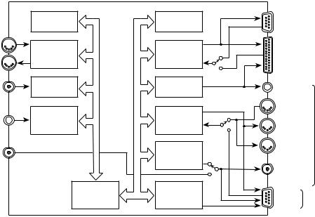
1.2F Block Diagram
The following AI-2 block diagram shows how the functional blocks in the AI-2 and the physical connectors are related.
|
Config. Sw. |
Front Panel |
|
|
Inputs |
LED Status |
|
MIDI In |
Aux. |
RS422 |
|
|
MIDI |
||
MIDI Out |
Port |
||
Port |
|||
(MTC) |
|
||
|
|
||
Video |
Video Sync |
Time Code |
|
Input |
Detector |
Generator |
RDR |
Wideband |
Input |
Time Code |
(LTC) |
Reader |
W/C Input (48K)
ADAT
MIDI
Port
Sample |
Clock |
Generator |
ADAT
CPU Time Code
Generator
Editor
(SONY P2)
Lynx-2 /
Micro Lynx
Gen |
|
|
Out |
|
|
In |
|
|
Out |
BRC |
|
|
||
Thru |
|
|
W/C Out |
||
(48K) |
|
|
Sync |
ADAT |
|
Out |
||
|
||
AI2001A |
||
5
1.3 INPUT CONTROL MODES
The AI-2 can be controlled by one of four methods.
1.The AI-2 and the attached ADATs are controlled by a video editor, or similar device, via a RS422 cable using standard Sony protocols. The AI-2 emulates the functionality of the Sony PCM7030 digital audio tape recorder.
2.The AI-2 and the attached ADATs are controlled by a TimeLine Lynx-2, Micro Lynx, or other synchronizer, using an interface cable supplied by the synchronizer manufacturer. This cable carries both control and time code information between the two devices.
3.The AI-2 and the attached ADATs chase (follow) SMPTE or EBU time code, which is fed into the AI-2's time code reader input.
4.The AI-2 and the attached ADATs are controlled by MIDI Machine Control (MMC) commands presented at the AI-2’s Control MIDI Input.
1.4OUTPUT CONTROL MODES
The AI-2 can control ADAT transports by one of two methods.
1.The AI-2 directly controls up to 16 ADAT recorders using the proprietary Alesis daisy-chain cabling technique used when multiple ADAT's are connected. The BRC Remote Control is not used. The digital audio sample rate clock (word clock) for the ADAT is generated by the AI-2.
2.The AI-2 controls the ALESIS BRC Remote Control, which is then used to directly control up to 16 ADATs. The AI-2 controls the BRC, using MIDI, word clock and time code signals.
6

1.5 "ENGAGED" VS. "DISENGAGED" TAPES
Analog audio recorders typically move tape past the heads between 1-7/8 and 30 inches per second. Higher play speeds result in a higher bandwidth, or the ability to record high-frequency signals on tape.
ADAT digital audio signals require a much higher bandwidth than analog audio. To provide the increased bandwidth required, the ADAT uses a VHS mechanism, which has a head drum that rotates at very high speeds and records the digital audio on diagonal tape tracks. This has the same effect, as far as the head is concerned, as moving the tape at a much faster speed.
With ADAT, the tape is "engaged" if the tape is not moving, but is in contact with the rotating head. This allows the ADAT to go into Play or Record, instantaneously. When the AI-2 puts the system into Still or Stop, the head remains spinning and the tape is not disengaged.
When the tape is "disengaged", the ADAT head stops rotating and the tape moves away from the head -- to prolong both tape and head life. If the tape is disengaged, the ADAT will take slightly longer to go into Play or Record as the tape has to engage. This type of transport operation is identical to the operation of a normal video tape transport.
The AI-2 will disengage the ADAT tape if it receives an Allstop command and will engage the tape on receiving any transport command, including Stop. The ADAT transport will automatically disengage the tape to minimize wear if no transport activity occurs after a period of 4 minutes.
7

CHAPTER 2: INSTALLATION
The AI-2 is a 1 unit high 19" Rack mount device. We recommend that you install the AI-2 in the same rack or close to the ADAT transports, permitting connection to the first ADAT transport with a standard ALESIS 9-pin sync cable. If it is not possible to locate the AI-2 adjacent to the ADAT, then the sync cable should be kept as short as possible because the cable carries a high frequency sample clock signal (48.000 KHz) which will degrade over distance.
The AI-2 rear panel provides connectors for the system timing reference, controllers, the BRC and the ADAT machine chain.
Hook up the wall mounting power supply and control cables and power on the AI-2, check that the front panel LCD backlight illuminates.
2.0 POWER CONNECTION
Power for the AI-2 is provided by a 10 volt AC, 7.5 VA wall mounting transformer, connect the output from the transformer to the 2.5 mm jack socket marked POWER. The AI-2 power input circuitry is designed to accept 9-12V AC. It will also accept a 9-12V DC input voltage of either polarity.
2.1 CONFIGURATION SWITCH
Next to the power connector is an eight position dip switch, which is used to configure default setups and the AI-2 MIDI IDs.
DS #1 |
25 Frame initialization default |
DS #2 |
Extended play tape times |
DS #3 |
Defeat power up sequence |
DS #4 |
Enable Setup mode Read Only option |
DS #5 |
Midi device ID# |
DS #6 |
Midi device ID# |
DS #7 |
Reserved |
DS #8 |
Reserved |
It is not necessary to alter any of these dip switches now, except for dip switch one (DS #1), which is used to default the AI-2 for 25 Frame operation after a system ram clear. If you are using the
AI-2 in Europe or will always be working with EBU time code then we suggest that you set dip switch one ON.
8

2.2 REFERENCE CONNECTION
The AI-2 reference connections are used to connect an external speed reference. Connectors are provided for time code, word clock and video signals. These signals are used to control the speed the ADAT machines will run at when in Play.
2.2A RDR IN
The RDR IN connector is a 1/4" TRS jack. The reader input is differential with an input impedance >10k ohms and an input range of -20 to +10 dBm. Connect a Longitudinal Time Code (LTC) feed to this input when it is required to resolve the speed of the system to time code or use the AI-2 as a time code chase synchronizer for the ADATs.
2.2B W/C IN
The W/C IN connector is a female BNC socket. The word clock input is 5 volt TTL. Connect a word clock reference source to this input when it is required to resolve the speed of the system to an external digital sample rate signal (word clock). The AI-2 word clock input range is greater than the ADAT control range of 40.36350.854 KHz. Input signals with a 50% duty cycle are recommended.
2.2C VID IN
The VID IN connector is a female BNC socket. The video input is single ended with an input impedance >2k ohms and an input signal range of 0.5-8.0 Vpp. Connect a video signal to this input when it is required to resolve the speed of the system to video sync. The video input will accept properly terminated Black burst, Color bars or Composite sync. We do not recommend connecting the output of a video tape transport.
The AI-2 video in connector can also be used as a video output if the TimeLine Video Sync Generator card (VSG) is fitted inside the AI-2. The VSG, can be used to generate composite sync at black level, which is locked to the ADAT system reference. This ability is extremely useful when a video deck needs to be locked to an ADAT system and for some reason it is not possible to lock the entire system to external video sync.
9

2.3 CONTROL CONNECTION
The AI-2 control connections are used to connect an external controller. Connectors are provided for a video editor or similar controller, the TimeLine Lynx-2 or Micro Lynx synchronizers, and MIDI. These inputs are used to control connected ADATs through the AI-2. The reader input can also be considered a control source when the AI-2 is operating in time code chase mode.
2.3A EDITOR
The EDITOR connector is a 9-pin D type socket. The editor connector conforms to the standard RS422 configuration and operates asynchronously at a standard transmission rate of 38.4
Kbits per second. The editor port communications are Sony serial protocol. Connect a 9-pin RS422 cable from an editor port to this socket when it is required to control the AI-2 from a video editor.
The AI-2 emulates the SONY PCM-7030 digital audio tape recorder, for best results select this device driver in the editor.
2.3B LYNX-2/MICRO LYNX
The LYNX-2/MICRO LYNX connector is a 25-pin D type socket. The Lynx-2/Micro Lynx connector is an integral synchronizer connector that contains RS422 communications, time code and a system frame reference. Connect a TimeLine ADAT interface cable from the Lynx-2 or Micro Lynx transport connector to this socket when it is required to synchronize ADATs in a TimeLine machine control system.
2.3C MIDI IN
The MIDI IN connector is a 5-pin din socket. The MIDI input is used for MIDI Machine Control (MMC), external MIDI commands to the AI-2, and feed through commands to the BRC, when connected. Connect a MIDI cable to this socket when it is required to control the AI-2 from an external MIDI device or controller.
10

2.3D MIDI OUT
The MIDI OUT connector is a 5-pin din socket. The MIDI output is used for MIDI Machine Control responses (MMC), AI-2 responses and BRC responses to external commands, and for MIDI Time Code (MTC). Connect a MIDI cable to this socket when using an external MIDI controller that requires MIDI responses.
2.4 BRC CONNECTION
The AI-2 BRC connections are used to connect a BRC to the AI-2. Connectors are provided for MIDI, time code and word clock. These signals are used to control the BRC which in turn controls the connected ADATs.
2.4A MIDI IN
The MIDI IN connector is a 5-pin din socket. Connect a MIDI cable to this input from the BRC MIDI output. BRC MIDI responses to
AI-2 or external requests are returned via this cable.
2.4B MIDI OUT
The MIDI OUT connector is a 5-pin din socket. Connect a MIDI cable from this output to the BRC MIDI input. AI-2 or External MIDI commands are sent to the BRC and ADATs via this cable.
2.4C MIDI THRU
The MIDI THRU connector is a 5-pin din socket. Connect a MIDI cable to this socket if MIDI output responses from the BRC are required.
2.4D GEN OUT
The GEN OUT connector is a 1/4" TRS jack. The generator output is an unbalanced, longitudinal time code feed with a fixed level of 1.0 Vpp. Connect a 1/4" to 1/4" audio jack cable from this output to the BRC SMPTE IN connector. The BRC uses the AI-2 time code output as it's time code chase input. When ADATs are controlled directly by the AI-2 the generator outputs the LTC value for the current ADAT position.
11

2.4E W/C OUT
The W/C OUT connector is a female BNC socket. The word clock output is a 5V TTL signal. Connect a BNC to BNC cable from this output to the BRC 48 KHz input. This connector feeds either external word clock or the AI-2 sample clock generator output
to the BRC.
2.5 ADAT CONNECTION
The AI-2 ADAT connection is used to connect the AI-2 to the first ADAT machine, Successive ADATs are connected in turn, sync out to sync in. This connector is not used when a BRC is configured as part of the system.
2.5A SYNC OUT
The SYNC OUT connector is a 9-pin D type socket. The sync out connector is used for direct connection to the ADAT machine chain.
Connect a male 9-pin D type cable from this connector to the sync in connector on the first ADAT machine. This connector supplies commands, 48 KHz clock and Alesis ADAT proprietary synchronization control information to the ADAT machines.
12
13
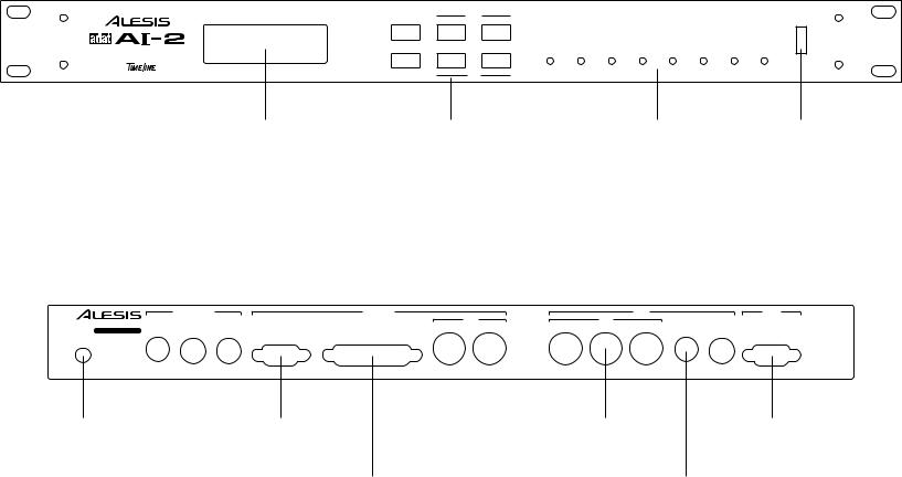
FRONT PANEL
|
|
|
CAPTURE |
|
|
|
|
|
|
|
|
|
SETUP |
SET/HOLD |
STORE |
|
|
|
|
|
|
|
POWER |
|
|
LAST |
NEXT |
|
|
|
|
|
|
|
|
MULTIPURPOSE AUDIO/VIDEO |
DISPLAY |
SAVE |
ONLINE |
ONLINE |
LOCK |
NON STD |
BRC/ADAT |
MMC |
CONTROL |
REF |
LTC |
SYNCHRONIZATION INTERFACE |
|
|
|
|
|
|
|
|
|
|
|
BY |
MENU |
DOWN |
UP |
|
|
|
|
|
|
|
|
|
|
|
|
|
|
|
|
|
|||
|
|
|
CLEAR |
|
|
|
|
|
|
|
|
LCD Display |
AI-2 Control and Setup |
Control and Communication |
Power Switch |
|
Keys |
Status LEDs |
|
Reader Input |
Word Clock Out |
1/4" TRS Jack |
BNC Connector |
REAR PANEL |
|
|
|
|
|
|
|
|
|
|
|
|
|
|
|
|
||||
|
|
|
|
|
|
REFERENCE |
|
|
|
CONTROL |
|
|
|
|
BRC |
|
|
ADAT |
||
ALESIS CORPORATION, LOS ANGELES |
|
|
|
|
|
|
|
|
MIDI |
|
MIDI |
|
|
|
|
|||||
|
|
|
|
|
|
|
IN |
|
OUT |
IN |
OUT |
THRU |
|
|
|
|||||
S/N |
|
|
RDR |
IN |
W/C IN |
VID IN |
EDITOR |
|
|
W/C |
OUT |
SYNC OUT |
||||||||
|
|
LYNX-2 / MICRO LYNX |
|
|
|
|
GEN OUT |
|||||||||||||
POWER |
CONFIG |
|
|
|
|
|
|
|
|
|
|
|
|
|
|
|
|
|||
|
|
|
|
|
|
|
|
|
|
|
|
|
|
|
|
|
|
|
||
|
|
|
|
|
|
|
|
|
|
|
|
|
|
|
THIS DEVICE COMPLIES WITH PART 15 OF THE FCC RULES. OPERATION IS SUBJECT TO THE FOLLOWING TWO CONDITIONS: (1) THIS DEVICE MAY NOT CAUSE |
|||||
|
|
|
|
|
|
|
|
|
|
|
|
|
|
|
||||||
MANUFACTURED BY TimeLine |
Vista, Inc. MADE IN USA |
|
|
|
|
|
|
|
|
|
||||||||||
|
|
|
|
CAUTION: TO PREVENT ELECTRICAL SHOCK DO NOT REMOVE COVERS. NO USER SERVICEABLE PARTS INSIDE. REFER SERVICING TO QUALIFIED |
SERVICE PERSONNEL. |
HARMFUL INTERFERENCE, AND (2) THIS DEVICE MUST ACCEPT ANY INTERFERENCE RECEIVED, INCLUDING INTERFERENCE THAT MAY CAUSE UNDESIRED OPTERATIONS. |
||||||||||||||
|
|
|
|
|
|
|
|
|
|
|
|
|
|
|
|
|
|
|
|
AI2021A |
|
|
|
|
|
|
|
|
|
|
|
|
|
|
|
|
|
|
|
||
9-12V AC Power |
|
Word Clock Input |
|
|
Editor 9 Pin |
|
MIDI In/Out |
|
BRC MIDI |
|
|
|
Sync Out |
|||||||
Connector |
|
BNC Connector |
|
|
D Connector |
|
5 Pin Din Connector |
5 Pin Din Connector |
9 Pin D Connector |
|||||||||||
|
|
|
|
|
|
|
|
|
|
|
|
|
|
|
|
|
|
|||
Eight Position |
|
Video Input |
Lynx-2/Micro Lynx |
|
|
|
|
Generator Out |
|
|||||||||||
Configuration |
BNC Connector |
Synchronizer |
|
|
|
|
1/4" TRS Jack |
|
||||||||||||
|
Switch |
|
|
|
|
|
25 Pin D Connector |
|
|
|
|
|
|
|
|
|||||

CHAPTER 3: APPLICATIONS
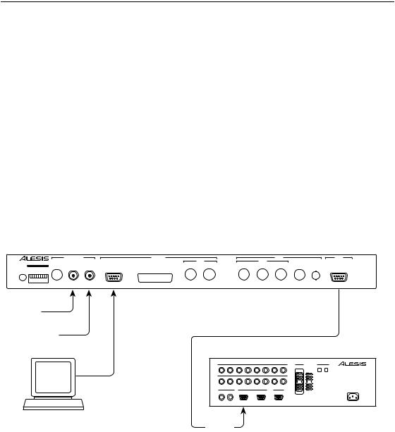
3.0 AI-2 INTERFACING
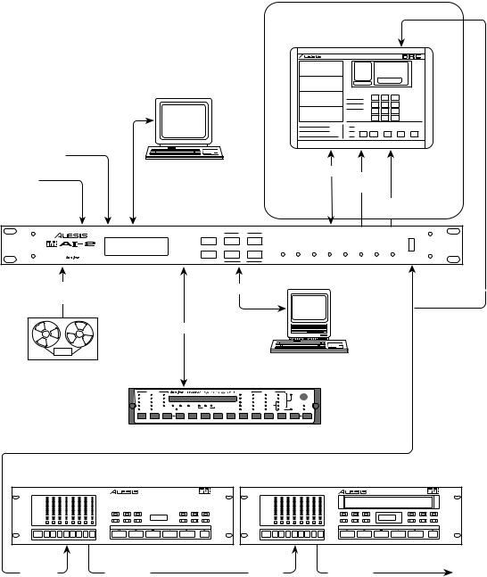
The AI-2 is designed to quickly and effectively integrate the Alesis ADAT digital audio tape recorders into studio and post production facilities. The AI-2 can be used for a wide range of applications, from basic chase synchronization to full control of 16 ADAT transports from a video editor. The first diagram shows a generic configuration, indicating a number of possible applications.
AI-2 APPLICATIONS |
Optional-See Section 3.2 |
|
|
VIDEO EDITOR |
ALESIS BRC |
|
|
|
|
|
|
|
|
|
|
|
I |
|
VIDEO |
|
|
|
|
|
|
|
|
|
|
O |
|
|
|
|
|
PUNCH IN/OUT LOCATE/PLAY SMPTE IN SMPTE OUT 48 kHz IN 48 kHz OUT |
VIDEO SYNC IN MIDI IN |
MIDI OUT REMOTE OUT TO ADAT |
|
90-250 VAC 50-60 Hz POWER ON/OFF |
||||
REFERENCE |
|
|
|
|
|
|
|
|
|
|
||
EXT WORD |
|
|
|
|
|
|
|
Time |
|
|
||
CLOCK |
|
|
|
|
MIDI |
|
|
|
||||
|
|
|
|
|
|
|
Code |
|
||||
ALESIS AI-2 |
|
|
|
|
|
|
|
|
Word |
|
||
|
|
|
|
|
|
|
|
Clock |
|
|||
|
REFERENCE |
|
CONTROL |
|
|
|
|
BRC |
|
|
ADAT |
|
ALESIS CORPORATION, LOS ANGELES |
|
|
|
MIDI |
|
MIDI |
|
|
|
|
||
|
|
IN |
OUT |
IN |
OUT |
THRU |
GEN OUT |
|
|
|||
S/N |
RDR IN W/C IN VID IN |
EDITOR |
LYNX-2 / MICRO LYNX |
W/C OUT |
SYNC OUT |
|||||||
|
|
|
|
|
|
|||||||
POWER |
CONFIG |
|
|
|
|
|
|
|
|
|
|
|
MANUFACTURED BY TimeLine Vista, Inc. MADE IN USA |
|
|
|
|
THIS DEVICE COMPLIES WITH PART 15 OF THE FCC RULES. OPERATION IS SUBJECT TO THE FOLLOWING TWO CONDITIONS: (1) THIS DEVICE MAY NOT CAUSE |
|||||||
CAUTION: TO PREVENT ELECTRICAL SHOCK DO NOT REMOVE COVERS. NO USER SERVICEABLE PARTS INSIDE. REFER SERVICING TO QUALIFIED SERVICE PERSONNEL. |
HARMFUL INTERFERENCE, AND (2) THIS DEVICE MUST ACCEPT ANY INTERFERENCE RECEIVED, INCLUDING INTERFERENCE THAT MAY CAUSE UNDESIRED OPTERATIONS. |
|||||||||||
|
Time Code |
|
|
MIDI |
|
|
|
|
|
|
||
|
Chase |
|
|
|
|
|
|
|
|
|
|
|
|
|
|
Control |
|
|
|
|
|
|
|
When using BRC with AI-2, |
|
|
|
|
|
|
|
|
|
|
|
Sync connection is from |
||
|
|
|
|
|
|
|
|
|
|
|
BRC to ADATs |
|
MIDI COMPUTER
AUDIO OR VIDEO
TRANSPORT
|
TRANSPORT |
|
|
|
|
|
|
|
|
|
GENERATOR |
|
|
LTC |
REC |
30 |
|
|
|
|
|
|
GEN |
29.97 |
JAM TC |
INT |
GEN |
VITC |
REH |
DF |
|
|
|
|
|
|
RDR |
30 |
JAM UB |
VID |
|
SER |
LOCK |
25 |
|
|
|
|
|
|
SYNC PT |
DF |
TACH |
AUX |
|
PILOT |
RESOLVE |
24 |
RMT BWL VARI |
H |
M |
L |
FILM |
VITC |
OFFSET |
25 |
N/STD |
MAINS |
422 |
TACH |
ONLINE |
|
|
|
SPEED |
|
|
|
ERR |
24 |
ON |
RDR |
VSO |
|
|
|
|
|
|
|
TIMELINE SYNCHRONIZER |
|
|
|
|
|
|
|
|
|
|||
MASTER ADAT |
|
|
|
|
SLAVE ADAT |
|
|
|
|
|
|||||||||
|
|
|
–10 dBV ANALOG INPUTS |
|
|
+4 dBu ANALOG |
OPTICAL |
|
|
|
–10 dBV ANALOG INPUTS |
|
|
+4 dBu ANALOG |
OPTICAL |
||||
1 |
2 |
3 |
4 |
5 |
6 |
7 |
8 |
DIGITAL |
DIGITAL |
1 |
2 |
3 |
4 |
5 |
6 |
7 |
8 |
DIGITAL |
DIGITAL |
|
|
|
|
|
|
|
|
INPUT |
OUTPUT |
|
|
|
|
|
|
|
|
INPUT |
OUTPUT |
|
|
|
–10 dBV ANALOG OUTPUTS |
|
|
|
INPUT |
|
|
|
|
–10 dBV ANALOG OUTPUTS |
|
|
|
INPUT |
|
||
1 |
2 |
3 |
4 |
5 |
6 |
7 |
8 |
|
1 |
2 |
3 |
4 |
5 |
6 |
7 |
8 |
|
||
|
|
|
|
|
|
|
|
|
POWER REQUIREMENTS |
|
|
|
|
|
|
|
|
|
POWER REQUIREMENTS |
|
|
|
|
|
|
|
|
OUTPUT |
90-260 VAC |
|
|
|
|
|
|
|
|
OUTPUT |
90-260 VAC |
FOOTSWITCHES |
|
|
SYNC |
|
METER BRIDGE |
50-60 Hz |
FOOTSWITCHES |
|
|
SYNC |
|
METER BRIDGE |
50-60 Hz |
||||||
|
|
|
|
50 WATTS MAX |
|
|
|
|
50 WATTS MAX |
||||||||||
LOCATE/PLAY |
PUNCH |
|
IN |
OUT |
|
|
|
|
|
LOCATE/PLAY |
PUNCH |
|
IN |
OUT |
|
|
|
|
|
LRC REMOTE |
IN/OUT |
|
|
|
|
|
|
|
|
LRC REMOTE |
IN/OUT |
|
|
|
|
|
|
|
|
AI2019A
Sync In |
|
Sync Out |
|
Sync In |
|
Sync Out |
14
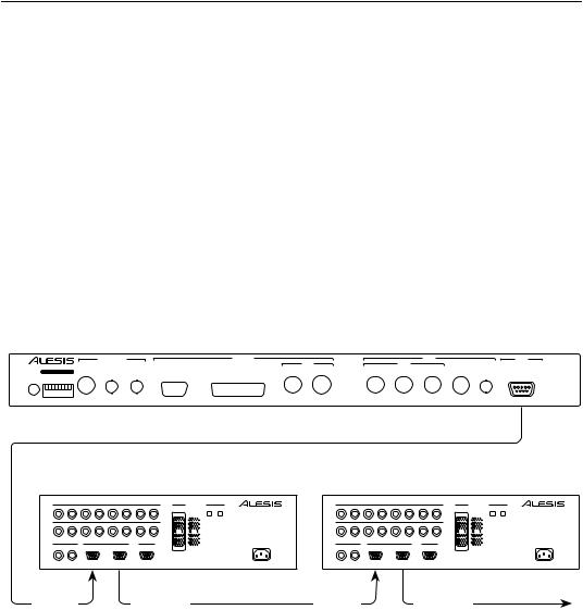
3.1 INTERFACING TO ONE OR MORE ADAT'S
The AI-2 is used to connect one or more ADATs to a control system. The basic ADAT connection is shown here. When the AI-2 is powered on it takes control of the ADAT chain and automatically assigns machine IDs to the connected ADATs. Although by itself the AI-2 cannot control the ADAT chain, if a reference source is connected to the AI-2, when the ADAT transports are put into play locally, the speed of the transports will be resolved to the selected reference by the AI-2.
Connect a standard Alesis ADAT interconnect cable between the AI-2 9-pin SYNC OUT connector and the SYNC IN connector of the
"master", or first, ADAT. Connect additional ADATs, SYNC OUT to
SYNC IN as described in the ADAT reference manual.
CONTROLLING ONE OR MORE ADAT'S (BASIC INTERFACE)
ALESIS AI-2
|
|
REFERENCE |
|
|
CONTROL |
|
|
|
|
BRC |
|
|
ADAT |
|
ALESIS CORPORATION, LOS ANGELES |
|
|
|
|
|
MIDI |
|
MIDI |
|
|
|
|
||
|
|
|
|
IN |
OUT |
IN |
OUT |
THRU |
GEN OUT |
|
|
|||
S/N |
RDR IN |
W/C IN |
VID IN |
EDITOR |
LYNX-2 / MICRO LYNX |
W/C OUT |
SYNC OUT |
|||||||
|
|
|
|
|
|
|||||||||
POWER |
CONFIG |
|
|
|
|
|
|
|
|
|
|
|
|
|
MANUFACTURED BY TimeLine Vista, Inc. MADE IN USA |
|
|
|
|
|
|
THIS DEVICE COMPLIES WITH PART 15 OF THE FCC RULES. OPERATION IS SUBJECT TO THE FOLLOWING TWO CONDITIONS: (1) THIS DEVICE MAY NOT CAUSE |
|||||||
|
|
CAUTION: TO PREVENT ELECTRICAL SHOCK DO NOT REMOVE COVERS. NO USER SERVICEABLE PARTS INSIDE. REFER SERVICING TO QUALIFIED SERVICE PERSONNEL. |
HARMFUL INTERFERENCE, AND (2) THIS DEVICE MUST ACCEPT ANY INTERFERENCE RECEIVED, INCLUDING INTERFERENCE THAT MAY CAUSE UNDESIRED OPTERATIONS. |
|||||||||||
MASTER ADAT |
|
|
|
|
SLAVE ADAT |
|
|
|
|
|
|||||||||
|
|
|
–10 dBV ANALOG INPUTS |
|
|
+4 dBu ANALOG |
OPTICAL |
|
|
|
–10 dBV ANALOG INPUTS |
|
|
+4 dBu ANALOG |
OPTICAL |
||||
1 |
2 |
3 |
4 |
5 |
6 |
7 |
8 |
DIGITAL |
DIGITAL |
1 |
2 |
3 |
4 |
5 |
6 |
7 |
8 |
DIGITAL |
DIGITAL |
|
|
|
|
|
|
|
|
INPUT |
OUTPUT |
|
|
|
|
|
|
|
|
INPUT |
OUTPUT |
|
|
|
–10 dBV ANALOG OUTPUTS |
|
|
|
INPUT |
|
|
|
|
–10 dBV ANALOG OUTPUTS |
|
|
|
INPUT |
|
||
1 |
2 |
3 |
4 |
5 |
6 |
7 |
8 |
|
1 |
2 |
3 |
4 |
5 |
6 |
7 |
8 |
|
||
|
|
|
|
||||||||||||||||
|
|
|
|
|
|
|
|
|
POWER REQUIREMENTS |
|
|
|
|
|
|
|
|
|
POWER REQUIREMENTS |
|
|
|
|
|
|
|
|
OUTPUT |
90-260 VAC |
|
|
|
|
|
|
|
|
OUTPUT |
90-260 VAC |
FOOTSWITCHES |
|
|
SYNC |
|
METER BRIDGE |
50-60 Hz |
FOOTSWITCHES |
|
|
SYNC |
|
METER BRIDGE |
50-60 Hz |
||||||
|
|
|
|
50 WATTS MAX |
|
|
|
|
50 WATTS MAX |
||||||||||
LOCATE/PLAY |
PUNCH |
|
IN |
OUT |
|
|
|
|
|
LOCATE/PLAY |
PUNCH |
|
IN |
OUT |
|
|
|
|
|
LRC REMOTE |
IN/OUT |
|
|
|
|
|
|
|
|
LRC REMOTE |
IN/OUT |
|
|
|
|
|
|
|
|
Sync In |
|
|
|
|
Sync Out |
|
|
Sync In |
|
|
|
|
Sync Out |
|
|
||||
AI2007A
When all the connections have been made, and the units powered on, the BRC/ADAT LED on the front panel of the AI-2 should be illuminated, to indicate that valid communication is occurring between the AI-2 and the ADAT units. If the LED does not light (no communications) or is flashing (communication taking place, but with errors) then recheck the cable connections.
15
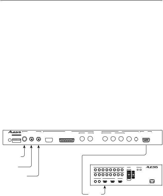
3.2 INTERFACING TO THE BRC
REMOTE CONTROL
The AI-2 can be used to control one or more ADATs through the BRC, this allows an "ADAT system" to be connected to a machine control system or video editing system. The AI-2 communicates with the control system and the BRC which can be used to provide such features as track enable buttons and MIDI song tempo mapping. The basic connections are shown below.
Connect the cables between the AI-2 BRC connector section and the BRC. Two standard MIDI cables from AI-2 MIDI IN to BRC MIDI OUT, and from AI-2 MIDI OUT to BRC MIDI IN. A standard BNC to BNC coaxial cable from AI-2 W/C OUT to BRC 48 KHz IN and a mono or stereo jack plug to jack plug cable from AI-2 GEN OUT to the BRC SMPTE input. Connect the BRC REMOTE OUT TO ADAT connector to the SYNC IN on the first ADAT transport.
CONTROLLING THE BRC
ALESIS AI-2
|
|
REFERENCE |
|
|
CONTROL |
|
|
|
|
BRC |
|
|
ADAT |
|
ALESIS CORPORATION, LOS ANGELES |
|
|
|
|
|
MIDI |
|
MIDI |
|
|
|
|
||
|
|
|
|
IN |
OUT |
IN |
OUT |
THRU |
GEN OUT |
|
|
|||
S/N |
RDR IN |
W/C IN |
VID IN |
EDITOR |
LYNX-2 / MICRO LYNX |
W/C OUT |
SYNC OUT |
|||||||
|
|
|
|
|
|
|||||||||
POWER |
CONFIG |
|
|
|
|
|
|
|
|
|
|
|
|
|
MANUFACTURED BY TimeLine Vista, Inc. MADE IN USA |
|
|
|
|
|
|
THIS DEVICE COMPLIES WITH PART 15 OF THE FCC RULES. OPERATION IS SUBJECT TO THE FOLLOWING TWO CONDITIONS: (1) THIS DEVICE MAY NOT CAUSE |
|||||||
|
|
CAUTION: TO PREVENT ELECTRICAL SHOCK DO NOT REMOVE COVERS. NO USER SERVICEABLE PARTS INSIDE. REFER SERVICING TO QUALIFIED SERVICE PERSONNEL. |
HARMFUL INTERFERENCE, AND (2) THIS DEVICE MUST ACCEPT ANY INTERFERENCE RECEIVED, INCLUDING INTERFERENCE THAT MAY CAUSE UNDESIRED OPTERATIONS. |
|||||||||||
Time Code
Word Clock
MIDI
MIDI
ALESIS BRC
I
O
PUNCH IN/OUT LOCATE/PLAY SMPTE IN |
SMPTE OUT 48 kHz IN |
48 kHz OUT VIDEO SYNC IN |
MIDI IN |
MIDI OUT |
REMOTE OUT TO ADAT |
90-250 VAC 50-60 Hz |
POWER ON/OFF |
MASTER ADAT |
|
|
|
|
SLAVE ADAT |
|
|
|
|
|
|||||||||
|
|
|
–10 dBV ANALOG INPUTS |
|
|
+4 dBu ANALOG |
OPTICAL |
|
|
|
–10 dBV ANALOG INPUTS |
|
|
+4 dBu ANALOG |
OPTICAL |
||||
1 |
2 |
3 |
4 |
5 |
6 |
7 |
8 |
DIGITAL |
DIGITAL |
1 |
2 |
3 |
4 |
5 |
6 |
7 |
8 |
DIGITAL |
DIGITAL |
|
|
|
|
|
|
|
|
INPUT |
OUTPUT |
|
|
|
|
|
|
|
|
INPUT |
OUTPUT |
|
|
|
–10 dBV ANALOG OUTPUTS |
|
|
|
INPUT |
|
|
|
|
–10 dBV ANALOG OUTPUTS |
|
|
|
INPUT |
|
||
1 |
2 |
3 |
4 |
5 |
6 |
7 |
8 |
|
1 |
2 |
3 |
4 |
5 |
6 |
7 |
8 |
|
||
|
|
|
|
|
|
|
|
|
POWER REQUIREMENTS |
|
|
|
|
|
|
|
|
|
POWER REQUIREMENTS |
|
|
|
|
|
|
|
|
OUTPUT |
90-260 VAC |
|
|
|
|
|
|
|
|
OUTPUT |
90-260 VAC |
FOOTSWITCHES |
|
|
SYNC |
|
METER BRIDGE |
50-60 Hz |
FOOTSWITCHES |
|
|
SYNC |
|
METER BRIDGE |
50-60 Hz |
||||||
|
|
|
|
50 WATTS MAX |
|
|
|
|
50 WATTS MAX |
||||||||||
LOCATE/PLAY |
PUNCH |
|
IN |
OUT |
|
|
|
|
|
LOCATE/PLAY |
PUNCH |
|
IN |
OUT |
|
|
|
|
|
LRC REMOTE |
IN/OUT |
|
|
|
|
|
|
|
|
LRC REMOTE |
IN/OUT |
|
|
|
|
|
|
|
|
AI2011A
Sync In |
|
Sync Out |
|
Sync In |
|
Sync Out |
|
|
|
|
|
|
|
|
|
|
|
|
|
|
16
Note, that the ADAT SYNC OUT connector on the AI-2 rear panel is unconnected for this mode of operation.
When all connections have been made, and the units powered on, the BRC/ADAT LED on the front panel of the AI-2 should be illuminated, to indicate that valid communication is occurring between the units. If the LED does not light (no communications) or is flashing (communication taking place, but with errors), then recheck the cable connections.
3.3 INTERFACING TO A VIDEO EDITOR
The AI-2 can be used to connect ADATs to a video editing system or other editing devices. The AI-2 provides a 9-pin SONY protocol VTR emulation for the ADAT transport. The AI-2 offers a number of editor specific functions such as selectable E-E and record field options and a comprehensive track mapping menu that maps editor track enables to selected ADAT tracks or machines.
Connect a standard RS422 cable from the 9-pin EDITOR connector in the control section of the AI-2 rear panel to a control output port on the editor. Connect a video reference signal to the VID IN connector in the reference section of the AI-2 rear panel. This video reference can be either black burst, color bars or composite sync, at either video or sync levels. The AI-2 normally emulates the SONY PCM-7030 DAT recorder, if the editor does not recognize this ID then the AI-2 emulation can be set to BVU950. Consult the Appendix for further details about emulation constants.
EDITOR INTERFACE
ALESIS AI-2
|
|
REFERENCE |
|
|
CONTROL |
|
|
|
|
BRC |
|
|
ADAT |
|
ALESIS CORPORATION, LOS ANGELES |
|
|
|
|
|
MIDI |
|
MIDI |
|
|
|
|
||
|
|
|
|
IN |
OUT |
IN |
OUT |
THRU |
GEN OUT |
|
|
|||
S/N |
RDR IN |
W/C IN |
VID IN |
EDITOR |
LYNX-2 / MICRO LYNX |
W/C OUT |
SYNC OUT |
|||||||
|
|
|
|
|
|
|||||||||
POWER |
CONFIG |
|
|
|
|
|
|
|
|
|
|
|
|
|
MANUFACTURED BY TimeLine Vista, Inc. MADE IN USA |
|
|
|
|
|
|
THIS DEVICE COMPLIES WITH PART 15 OF THE FCC RULES. OPERATION IS SUBJECT TO THE FOLLOWING TWO CONDITIONS: (1) THIS DEVICE MAY NOT CAUSE |
|||||||
|
|
CAUTION: TO PREVENT ELECTRICAL SHOCK DO NOT REMOVE COVERS. NO USER SERVICEABLE PARTS INSIDE. REFER SERVICING TO QUALIFIED SERVICE PERSONNEL. |
HARMFUL INTERFERENCE, AND (2) THIS DEVICE MUST ACCEPT ANY INTERFERENCE RECEIVED, INCLUDING INTERFERENCE THAT MAY CAUSE UNDESIRED OPTERATIONS. |
|||||||||||
(EXT WORD CLOCK)
VIDEO
REFERENCE
EDITOR |
ALESIS ADAT |
|
|
|
–10 dBV ANALOG INPUTS |
|
|
+4 dBu ANALOG |
OPTICAL |
||
1 |
2 |
3 |
4 |
5 |
6 |
7 |
8 |
DIGITAL |
DIGITAL |
|
|
|
|
|
|
|
|
INPUT |
OUTPUT |
|
|
|
–10 dBV ANALOG OUTPUTS |
|
|
|
INPUT |
|
|
1 |
2 |
3 |
4 |
5 |
6 |
7 |
8 |
|
|
|
|
||||||||
|
|
|
|
|
|
|
|
|
POWER REQUIREMENTS |
|
|
|
|
|
|
|
|
OUTPUT |
90-260 VAC |
FOOTSWITCHES |
|
|
SYNC |
|
METER BRIDGE |
50-60 Hz |
|||
|
|
|
|
50 WATTS MAX |
|||||
LOCATE/PLAY |
PUNCH |
|
IN |
OUT |
|
|
|
|
|
LRC REMOTE |
IN/OUT |
|
|
|
|
|
|
|
|
AI2008A
Sync In
17

If required, an external digital audio sample rate clock may also be connected to the W/C IN connector in the reference section of the AI-2 rear panel. For the system to operate satisfactorily, the external sample rate clock must be correctly synchronized to the video reference signal connected to the video input.
When the Editor is connected and communicating correctly, the CONTROL LED on the front panel of the AI-2 should be illuminated, to indicate that valid communication is occurring between the units. If the LED does not light (no communications) or is flashing (communication taking place, but with errors), then recheck the cable connections.
The REF LED on the AI-2 front panel should also be illuminated, indicating the presence of a valid video reference. If the REF LED is flashing then check that a valid source of video sync is connected.
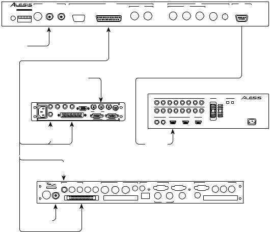
3.4 INTERFACING TO THE LYNX-2 OR MICRO LYNX
The AI-2 has a special control connector for interfacing to the TimeLine Lynx-2 and Micro Lynx synchronizers. To simplify the machine control interface this connector supplies machine control commands, time code and a system timing signal all in a single cable. The latest versions of TimeLine software include special optimized drivers for the ADAT machine and new features such as expanded track support up to 128 tracks. The TimeLine interface permits ADAT machines to be used in literally any situation where ADATs need to be synchronized with other transports, film, video or audio.
Connect a TimeLine ADAT interface cable from the LYNX-2/ MICRO LYNX connector in the control section of the AI-2 rear panel to the appropriate transport connector on the synchronizer. The synchronizer end of this cable has a small pigtail cable with a 1/4" plug attached. This is the AI-2 time code line and should be plugged into the appropriate time code reader input.
Connect a video reference signal to the VID IN connector in the reference section of the AI-2 rear panel. For a Lynx-2 or Micro Lynx system, it is not necessary to connect a video reference to the AI-2 video input, however it should be connected as a matter of good practice, even if the synchronizer is using video sync as a reference. The original Lynx synchronizer, as well as other synchronizer systems require video sync to be connected to operate correctly. Refer to the appendix for more information on interfacing with
the Lynx.
18
An external digital audio word clock can be connected to the reference W/C IN connector. The same precautions apply as for the video editor interface, the word clock and synchronizer system must both be locked to the same reference signal. For example, if the synchronizer system is referenced to video sync, then the word clock must also be referenced to video sync.
LYNX-2 OR MICRO LYNX INTERFACE
ALESIS AI-2
|
|
REFERENCE |
|
|
CONTROL |
|
|
|
|
BRC |
|
|
ADAT |
|
ALESIS CORPORATION, LOS ANGELES |
|
|
|
|
|
MIDI |
|
MIDI |
|
|
|
|
||
|
|
|
|
IN |
OUT |
IN |
OUT |
THRU |
GEN OUT |
|
|
|||
S/N |
RDR IN |
W/C IN |
VID IN |
EDITOR |
LYNX-2 / MICRO LYNX |
W/C OUT |
SYNC OUT |
|||||||
|
|
|
|
|
|
|||||||||
POWER |
CONFIG |
|
|
|
|
|
|
|
|
|
|
|
|
|
MANUFACTURED BY TimeLine Vista, Inc. MADE IN USA |
|
|
|
|
|
|
THIS DEVICE COMPLIES WITH PART 15 OF THE FCC RULES. OPERATION IS SUBJECT TO THE FOLLOWING TWO CONDITIONS: (1) THIS DEVICE MAY NOT CAUSE |
|||||||
|
|
CAUTION: TO PREVENT ELECTRICAL SHOCK DO NOT REMOVE COVERS. NO USER SERVICEABLE PARTS INSIDE. REFER SERVICING TO QUALIFIED SERVICE PERSONNEL. |
HARMFUL INTERFERENCE, AND (2) THIS DEVICE MUST ACCEPT ANY INTERFERENCE RECEIVED, INCLUDING INTERFERENCE THAT MAY CAUSE UNDESIRED OPTERATIONS. |
|||||||||||
(EXT WORD CLOCK)
VIDEO
REFERENCE (OPT)
|
|
ALESIS ADAT |
|
|
|
|
|
||||
LYNX-2 |
|
1 |
2 |
3 |
4 |
5 |
6 |
7 |
8 |
DIGITAL |
DIGITAL |
|
|
|
|
|
–10 dBV ANALOG INPUTS |
|
|
+4 dBu ANALOG |
OPTICAL |
||
|
|
|
|
|
|
|
|
|
|
INPUT |
OUTPUT |
AUX |
|
|
|
|
|
|
|
|
|
|
|
|
|
|
|
|
–10 dBV ANALOG OUTPUTS |
|
|
|
INPUT |
|
|
|
|
1 |
2 |
3 |
4 |
5 |
6 |
7 |
8 |
|
|
|
|
|
|
||||||||
RESHAPE GEN OUT PILOT IN PILOT OUT |
VITC |
MAC |
|
|
|
|
|
|
|
|
|
EXT VIDEO |
|
|
|
|
|
|
|
|
POWER REQUIREMENTS |
||
|
|
|
|
|
|
|
|
|
|
|
|
|
|
|
|
|
|
|
|
|
|
OUTPUT |
90-260 VAC |
|
|
FOOTSWITCHES |
|
|
SYNC |
|
METER BRIDGE |
50-60 Hz |
|||
|
|
|
|
|
|
50 WATTS MAX |
|||||
TC IN |
RS422 |
LOCATE/PLAY |
PUNCH |
|
IN |
OUT |
|
|
|
|
|
TRANSPORT |
LRC REMOTE |
IN/OUT |
|
|
|
|
|
|
|
|
|
TC RDR
In
Sync In
|
TC RDR |
|
|
|
|
|
|
|
|
|
|
|
|
|
|
In |
|
|
|
|
|
|
|
|
|
|
|
|
MICRO LYNX |
|
|
|
|
|
|
|
|
|
|
|
|
|
|
|
|
|
TIME CODE |
|
|
IN |
OUT |
MIDI |
I/F |
COMPUTER |
RS232/422 |
|
SYSTEM TALLY |
AES/EBU |
AUDIO CLOCK GENERATOR |
|
RDR 1 |
RDR 2 |
OUT |
AUX IN AUX OUT |
THRU/OUT |
MAC |
|
|
O.S. OUT WORD OUT CLOCK IN |
|||||
S/N |
|
|
|
|
|
|
|
|
|
|
|
|
|
|
MADE IN USA |
|
|
|
|
|
|
|
|
|
|
|
|
|
|
POWER |
VIDEO REF |
TRANSPORT 1 |
|
TRANSPORT 2 |
|
KEYBOARD |
IN |
THRU |
VIDEO OUT |
RDR 3 |
TRANSPORT 3 |
|||
|
|
VITC |
|
|||||||||||
VIDEO |
|
|
|
|
|
|
|
|
|
|
|
|
|
AI2023A |
|
|
|
|
|
|
|
|
|
|
|
|
|
|
|
REF (OPT) |
|
|
|
|
|
|
|
|
|
|
|
|
|
|
When the Lynx-2 or Micro Lynx is connected correctly the CONTROL LED on the front panel of the AI-2 should be illuminated, to indicate that valid communication is occurring between the units. If the LED does not light (no communications) or is flashing
(communication taking place, but with errors), then recheck the cable connections.
19
3.5 TIME CODE CHASE INTERFACE
The AI-2 has a high resolution bi-directional time code reader that has been specifically designed for time code chase applications. The reader can read all time code types, at any rate, including discontinuous high speed code. The AI-2 thereby ensures that ADAT tape recorders can be integrated into a system when only a time code feed is available. The AI-2 reader has a wide input range and an adjustable flywheel option to cater for bad time code. The reader input can also be selected as the system reference when it is necessary for the ADAT to lock to unreferenced or off speed code.
Connect the RDR IN connector in the reference section of the AI-2 rear panel to the reference or master time code with a standard mono or stereo jack plug cable.
In time code chase mode an optional video sync or word clock reference may be connected. If an external reference is supplied, the AI-2 will resolve the ADATs to the reference, while using the time code input as a numerical reference only.
TIME CODE CHASE INTERFACE
ALESIS AI-2
|
|
REFERENCE |
|
|
CONTROL |
|
|
|
|
BRC |
|
|
ADAT |
|
ALESIS CORPORATION, LOS ANGELES |
|
|
|
|
|
MIDI |
|
MIDI |
|
|
|
|
||
|
|
|
|
IN |
OUT |
IN |
OUT |
THRU |
GEN OUT |
|
|
|||
S/N |
RDR IN |
W/C IN |
VID IN |
EDITOR |
LYNX-2 / MICRO LYNX |
W/C OUT |
SYNC OUT |
|||||||
|
|
|
|
|
|
|||||||||
POWER |
CONFIG |
|
|
|
|
|
|
|
|
|
|
|
|
|
MANUFACTURED BY TimeLine Vista, Inc. MADE IN USA |
|
|
|
|
|
|
THIS DEVICE COMPLIES WITH PART 15 OF THE FCC RULES. OPERATION IS SUBJECT TO THE FOLLOWING TWO CONDITIONS: (1) THIS DEVICE MAY NOT CAUSE |
|||||||
|
|
CAUTION: TO PREVENT ELECTRICAL SHOCK DO NOT REMOVE COVERS. NO USER SERVICEABLE PARTS INSIDE. REFER SERVICING TO QUALIFIED SERVICE PERSONNEL. |
HARMFUL INTERFERENCE, AND (2) THIS DEVICE MUST ACCEPT ANY INTERFERENCE RECEIVED, INCLUDING INTERFERENCE THAT MAY CAUSE UNDESIRED OPTERATIONS. |
|||||||||||
TIME
CODE IN
(EXT WORD |
ALESIS ADAT |
|
|
|
|
|
||||
|
|
|
|
|
|
|
|
|
|
|
CLOCK) |
1 |
2 |
3 |
4 |
5 |
6 |
7 |
8 |
INPUT OUTPUT |
|
|
|
|
|
–10 dBV ANALOG INPUTS |
|
|
+4 dBu ANALOG |
OPTICAL |
|
|
|
|
|
|
|
|
|
|
|
DIGITAL DIGITAL |
|
(VIDEO |
|
|
|
–10 dBV ANALOG OUTPUTS |
|
|
|
INPUT |
|
|
|
1 |
2 |
3 |
4 |
5 |
6 |
7 |
8 |
|
|
REFERENCE) |
|
|
||||||||
FOOTSWITCHES |
|
|
SYNC |
|
METER BRIDGE |
|
50 WATTS MAX |
|||
|
|
|
|
|
|
|
|
|
|
POWER REQUIREMENTS |
|
|
|
|
|
|
|
|
|
OUTPUT |
90-260 VAC |
|
|
|
|
|
|
|
|
|
50-60 Hz |
|
|
LOCATE/PLAY PUNCH |
|
IN |
OUT |
|
|
|
|
|
|
|
LRC REMOTE IN/OUT |
|
|
|
|
|
|
|
|
|
AI2012A
Sync In
Similar precautions apply, when using an external word clock, as for the previous methods of operation. The word clock must be locked to either the video reference, if used, or to the time code which is being fed to the reader input.
20
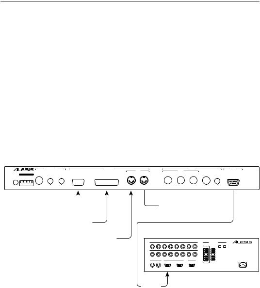
On the AI-2 front panel, the LTC LED will illuminate when valid time code is being received at the rear panel reader input. If the LED does not light or is flickering then check the time code cable or the output level of the time code source.
3.6 EXTERNAL MIDI INTERFACING MIDI MACHINE CONTROL
The AI-2 can be controlled from a MIDI controller or software program that generates MIDI Machine Control (MMC) commands. MIDI Machine Control commands and responses will operate simultaneously with either the Editor or Lynx-2/Micro Lynx synchronizer controllers. The AI-2 permits the seamless integration of ADAT transports into the electronic music studio as MIDI programs designed to control the BRC or ADAT machines can be operated without configuring the system.
MIDI Machine Control commands are fed to the AI-2 using a standard MIDI cable to the MIDI IN connector in the control section of the AI-2 rear panel. MIDI Machine Control responses will appear at the MIDI OUT connector. The MIDI out connector also optionally includes MIDI time code.
EXTERNAL MIDI INTERFACING MIDI MACHINE CONTROL
ALESIS AI-2
|
|
REFERENCE |
|
|
CONTROL |
|
|
|
|
BRC |
|
|
ADAT |
|
ALESIS CORPORATION, LOS ANGELES |
|
|
|
|
|
MIDI |
|
MIDI |
|
|
|
|
||
|
|
|
|
IN |
OUT |
IN |
OUT |
THRU |
GEN OUT |
|
|
|||
S/N |
RDR IN |
W/C IN |
VID IN |
EDITOR |
LYNX-2 / MICRO LYNX |
W/C OUT |
SYNC OUT |
|||||||
|
|
|
|
|
|
|||||||||
POWER |
CONFIG |
|
|
|
|
|
|
|
|
|
|
|
|
|
MANUFACTURED BY TimeLine Vista, Inc. MADE IN USA |
|
|
|
|
|
|
THIS DEVICE COMPLIES WITH PART 15 OF THE FCC RULES. OPERATION IS SUBJECT TO THE FOLLOWING TWO CONDITIONS: (1) THIS DEVICE MAY NOT CAUSE |
|||||||
|
|
CAUTION: TO PREVENT ELECTRICAL SHOCK DO NOT REMOVE COVERS. NO USER SERVICEABLE PARTS INSIDE. REFER SERVICING TO QUALIFIED SERVICE PERSONNEL. |
HARMFUL INTERFERENCE, AND (2) THIS DEVICE MUST ACCEPT ANY INTERFERENCE RECEIVED, INCLUDING INTERFERENCE THAT MAY CAUSE UNDESIRED OPTERATIONS. |
|||||||||||
EDITOR 
LYNX-2 / MICRO LYNX
MMC COMMANDS 1
1Operation in Parallel with either RS422 or Lynx-2 / Micro Lynx Control.
 MMC RESPONSES (Optionally includes MIDI Time Code)
ALESIS ADAT
|
|
|
–10 dBV ANALOG INPUTS |
|
|
+4 dBu ANALOG |
OPTICAL |
||
1 |
2 |
3 |
4 |
5 |
6 |
7 |
8 |
DIGITAL |
DIGITAL |
|
|
|
|
|
|
|
|
INPUT |
OUTPUT |
|
|
|
–10 dBV ANALOG OUTPUTS |
|
|
|
INPUT |
|
|
1 |
2 |
3 |
4 |
5 |
6 |
7 |
8 |
|
|
|
|
|
|
|
|
|
|
|
POWER REQUIREMENTS |
|
|
|
|
|
|
|
|
OUTPUT |
90-260 VAC |
FOOTSWITCHES |
|
|
SYNC |
|
METER BRIDGE |
50-60 Hz |
|||
|
|
|
|
50 WATTS MAX |
|||||
LOCATE/PLAY |
PUNCH |
|
IN |
OUT |
|
|
|
|
|
LRC REMOTE |
IN/OUT |
|
|
|
|
|
|
|
|
AI2009A
Sync In
21

During operation the MMC LED on the AI-2 front panel illuminates to indicate valid MIDI data is being received. If the LED does not light (no communications) or is flashing (communication taking place, but with errors), then recheck the MIDI cable connections and make sure that the MIDI controller or software is actually generating MMC messages.
Details of supported MIDI Machine Control commands and responses may be obtained by contacting TimeLine.
3.7 DIGITAL TRANSFER WITH THE AI-1
The AI-2 can be used with the Alesis AI-1 digital audio interface. This permits synchronized digital audio transfer to and from other multitrack digital audio tape recorders, DAT machines, digital audio workstations and synthesizers. The AI-1 transfers digital audio in the AES/EBU or S/PDIF formats. Both these formats use a self clocking signal and care should be taken to ensure that the digital audio equipment being synchronized is all locked to a common reference.
The AI-1 should be installed at the end of the ADAT chain after the last ADAT transport. Connect a standard Alesis sync cable from the AI-2 SYNC OUT to the SYNC IN connector of the first ADAT transport, connect further ADAT transports sync in to sync out, in the normal manner. Connect the SYNC OUT connector of the last ADAT to the AI-1 SYNC IN connector. Connect the ADAT proprietary multichannel optical digital interface so that there is a complete loop from the AI-1 digital output through all the ADAT transports, digital out to digital in, back to the AI-1 digital input. Connect a coaxial BNC to BNC cable from the AI-1 48 KHz output to the AI-2 W/C input.
The AI-2 requires the 48 KHz word clock signal from the AI-1 to ensure the timing and positional information, being sent to the ADATs, remains synchronous. If required an external video sync signal can be connected to the reference VID IN connector or synchronizer reference to the Lynx-2/Micro Lynx connector and the AI-2 will use these signals to derive a frame edge for external synchronization.
22
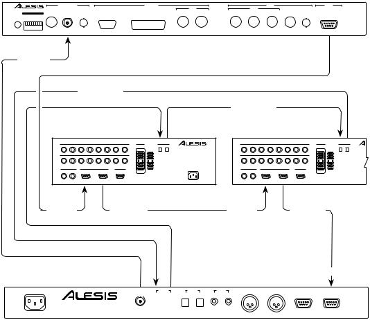
DIGITAL TRANSFER WITH THE AI-1
ALESIS AI-2
|
|
REFERENCE |
|
|
CONTROL |
|
|
|
|
BRC |
|
|
ADAT |
|
ALESIS CORPORATION, LOS ANGELES |
|
|
|
|
|
MIDI |
|
MIDI |
|
|
|
|
||
|
|
|
|
IN |
OUT |
IN |
OUT |
THRU |
GEN OUT |
|
|
|||
S/N |
RDR IN |
W/C IN |
VID IN |
EDITOR |
LYNX-2 / MICRO LYNX |
W/C OUT |
SYNC OUT |
|||||||
|
|
|
|
|
|
|||||||||
POWER |
CONFIG |
|
|
|
|
|
|
|
|
|
|
|
|
|
MANUFACTURED BY TimeLine Vista, Inc. MADE IN USA |
|
|
|
|
|
|
THIS DEVICE COMPLIES WITH PART 15 OF THE FCC RULES. OPERATION IS SUBJECT TO THE FOLLOWING TWO CONDITIONS: (1) THIS DEVICE MAY NOT CAUSE |
|||||||
|
|
CAUTION: TO PREVENT ELECTRICAL SHOCK DO NOT REMOVE COVERS. NO USER SERVICEABLE PARTS INSIDE. REFER SERVICING TO QUALIFIED SERVICE PERSONNEL. |
HARMFUL INTERFERENCE, AND (2) THIS DEVICE MUST ACCEPT ANY INTERFERENCE RECEIVED, INCLUDING INTERFERENCE THAT MAY CAUSE UNDESIRED OPTERATIONS. |
|||||||||||
Word
Clock In
Digital I/O
|
|
|
|
|
|
|
|
|
|
Digital I/O |
|
|
|
|
|
|||
MASTER ADAT |
|
|
|
|
SLAVE ADAT |
|
|
|
||||||||||
|
|
|
–10 dBV ANALOG INPUTS |
|
|
+4 dBu ANALOG |
OPTICAL |
|
|
|
|
–10 dBV ANALOG INPUTS |
|
+4 dBu ANALOG |
OPTICAL |
|||
1 |
2 |
3 |
4 |
5 |
6 |
7 |
8 |
DIGITAL DIGITAL |
|
1 |
2 |
3 |
4 |
5 |
6 |
7 |
8 |
DIGITAL DIGITAL |
|
|
|
|
|
|
|
|
INPUT OUTPUT |
|
|
|
|
|
|
|
|
|
INPUT OUTPUT |
|
|
|
–10 dBV ANALOG OUTPUTS |
|
|
|
INPUT |
|
|
|
|
–10 dBV ANALOG OUTPUTS |
|
|
INPUT |
|||
1 |
2 |
3 |
4 |
5 |
6 |
7 |
8 |
|
|
1 |
2 |
3 |
4 |
5 |
6 |
7 |
8 |
|
|
|
|
|
|
|
|
|
|
POWER REQUIREMENTS |
|
|
|
|
|
|
|
|
|
|
|
|
|
|
|
|
|
OUTPUT |
90-260 VAC |
|
|
|
|
|
|
|
|
OUTPUT |
FOOTSWITCHES |
|
|
SYNC |
|
METER BRIDGE |
50-60 Hz |
FOOTSWITCHES |
|
SYNC |
|
|
METER BRIDGE |
||||||
|
|
|
|
50 WATTS MAX |
|
|
|
|
||||||||||
LOCATE/PLAY PUNCH |
|
IN |
OUT |
|
|
|
|
|
LOCATE/PLAY PUNCH |
|
IN |
|
OUT |
|
|
|
||
LRC REMOTE IN/OUT |
|
|
|
|
|
|
|
|
LRC REMOTE IN/OUT |
|
|
|
|
|
|
|
||
Sync In |
|
|
|
|
Sync Out |
|
|
Sync In |
|
|
|
|
Sync Out |
|
||||
Sync In
ALESIS AI-1
48kHz OUT |
ADAT |
|
SPDIF |
|
SPDIF |
|
AES/EBU |
|
SYNC OUT |
SYNC IN |
||||
|
|
|
IN |
|
OUT |
IN |
OUT |
IN |
IN |
|
|
|
OUT |
|
|
|
|
|
OUT |
|
|
|
|
|
|||||
|
|
|
|
|
|
|
|
|
|
|
|
|
|
|
|
|
|
|
|
|
|
|
|
|
|
|
|
|
|
60-250 VAC 50-60 Hz
AI2018A
As for all the previous methods of operation, when using external references similar precautions apply. The reference signals must be locked together. The word clock signal from the AI-1 is derived from the incoming digital audio data, this must therefore be locked to the video or synchronizer reference for the system to operate correctly.
23
 Loading...